Page 3369 of 5267
Pressure Test Port Locations
Only two pressure ports are supplied on the transmis-
sion case. The torque converter clutch apply (3) and
release(1)portsarelocatedontherightsideofthe
transmission case.
To determine the line pressure, there are two available
methods. The scan tool can be used to read line pres-
sure from the line pressure sensor. The second
method is to install Line Pressure Adapter 8259 (3)
into the transmission case and then install the pres-
sure gauge and the original sensor (2) into the
adapter. This will allow a comparison of the scan tool
readings and the gauge reading to determine the
accuracy of the line pressure sensor. The scan tool
Page 3370 of 5267
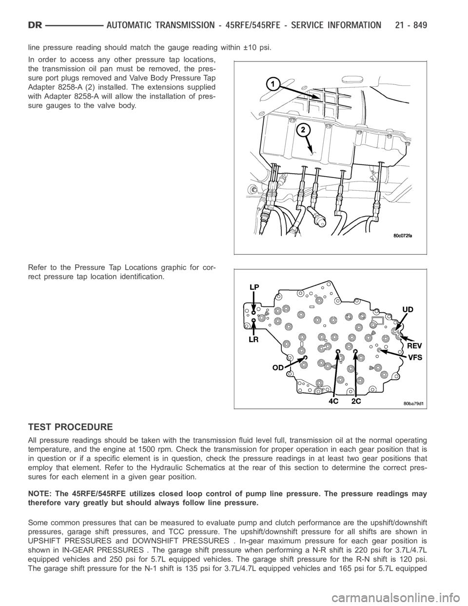
line pressure reading should match the gauge reading within ±10 psi.
In order to access any other pressure tap locations,
the transmission oil pan must be removed, the pres-
sure port plugs removed and Valve Body Pressure Tap
Adapter 8258-A (2) installed. The extensions supplied
with Adapter 8258-A will allow the installation of pres-
sure gauges to the valve body.
Refer to the Pressure Tap Locations graphic for cor-
rect pressure tap location identification.
TEST PROCEDURE
All pressure readings should be taken with the transmission fluid level full, transmission oil at the normal operating
temperature, and the engine at 1500 rpm. Check the transmission for properoperation in each gear position that is
in question or if a specific element is in question, check the pressure readings in at least two gear positions that
employ that element. Refer to the Hydraulic Schematics at the rear of this section to determine the correct pres-
sures for each element in a given gear position.
NOTE: The 45RFE/545RFE utilizes closed loop control of pump line pressure. The pressure readings may
therefore vary greatly but should always follow line pressure.
Some common pressures that can be measured to evaluate pump and clutch performance are the upshift/downshift
pressures, garage shift pressures, and TCC pressure. The upshift/downshift pressure for all shifts are shown in
UPSHIFT PRESSURES and DOWNSHIFT PRESSURES . In-gear maximum pressure foreach gear position is
shown in IN-GEAR PRESSURES . The garageshift pressure when performing a N-R shift is 220 psi for 3.7L/4.7L
equipped vehicles and 250 psi for 5.7L equipped vehicles. The garage shiftpressure for the R-N shift is 120 psi.
The garage shift pressure for the N-1 shift is 135 psi for 3.7L/4.7L equipped vehicles and 165 psi for 5.7L equipped
Page 3371 of 5267
vehicles. Torque converter lock-up pressure is 120 psi for 3.7L/4.7L equipped vehicles and 125 psi for 5.7L
equipped vehicles.
UPSHIFT PRESSURES
ENGINE 1-2 2-3 2prime-3 3-4 2prime-4 2-5 3-5 4-5
5.7L150 125 125 135 135 135 135 135
3.7L/4.7L120 120 120 120 120 120 120 130
DOWNSHIFT PRESSURES
ENGINE 5-4 5-3 5-2 4-3 4-
2prime3-2 3-
2prime2prime-1 2-1 3-1
5.7L135 135 135 135 135 135 135 135 135 135
3.7L/
4.7L120 120 120 120 120 120 120 120 120 120
IN-GEAR PRESSURES
ENGINE122prime345NEUTRALREVERSE
5.7L160 135 135 135 135 135 120 250
3.7L/4.7L135 120 120 120 120 120 120 220
AIR CHECKING TRANSMISSION CLUTCH OPERATION
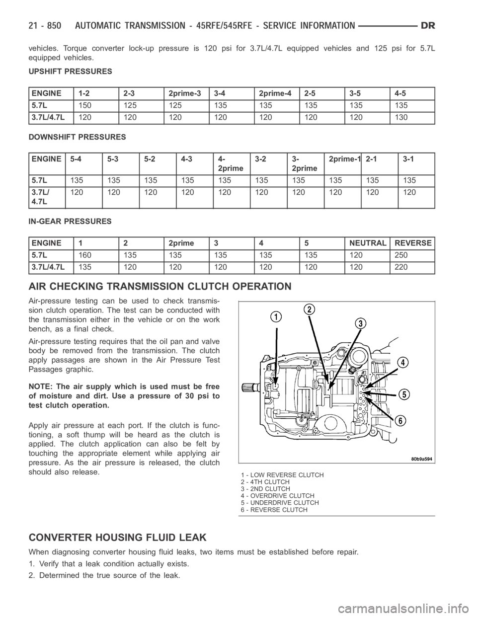
Air-pressure testing can be used to check transmis-
sion clutch operation. The test can be conducted with
the transmission either in the vehicle or on the work
bench, as a final check.
Air-pressure testing requires that the oil pan and valve
body be removed from the transmission. The clutch
apply passages are shown in the Air Pressure Test
Passages graphic.
NOTE: The air supply which is used must be free
ofmoistureanddirt.Useapressureof30psito
test clutch operation.
Apply air pressure at each port. If the clutch is func-
tioning, a soft thump will be heard as the clutch is
applied. The clutch application can also be felt by
touching the appropriate element while applying air
pressure. As the air pressure is released, the clutch
should also release.
CONVERTER HOUSING FLUID LEAK
When diagnosing converter housing fluid leaks, two items must be established before repair.
1. Verify that a leak condition actually exists.
2. Determined the true source of the leak.
1 - LOW REVERSE CLUTCH
2 - 4TH CLUTCH
3 - 2ND CLUTCH
4-OVERDRIVECLUTCH
5 - UNDERDRIVE CLUTCH
6 - REVERSE CLUTCH
Page 3376 of 5267
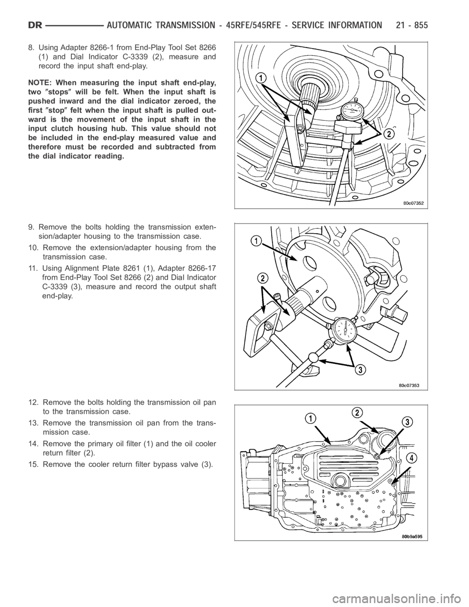
8. Using Adapter 8266-1 from End-Play Tool Set 8266
(1) and Dial Indicator C-3339 (2), measure and
record the input shaft end-play.
NOTE: When measuring the input shaft end-play,
two
stopswill be felt. When the input shaft is
pushed inward and the dial indicator zeroed, the
first
stopfelt when the input shaft is pulled out-
wardisthemovementoftheinputshaftinthe
input clutch housing hub. This value should not
be included in the end-play measured value and
therefore must be recorded and subtracted from
the dial indicator reading.
9. Remove the bolts holding the transmission exten-
sion/adapter housing to the transmission case.
10. Remove the extension/adapter housing from the
transmission case.
11. Using Alignment Plate 8261 (1), Adapter 8266-17
from End-Play Tool Set 8266 (2) and Dial Indicator
C-3339 (3), measure and record the output shaft
end-play.
12. Remove the bolts holding the transmission oil pan
to the transmission case.
13. Remove the transmission oil pan from the trans-
mission case.
14. Remove the primary oil filter (1) and the oil cooler
return filter (2).
15. Remove the cooler return filter bypass valve (3).
Page 3377 of 5267
16. Remove the bolts (1) holding the valve body to
the transmission case.
17. Remove the valve body from the transmission
case.
18. Remove the outer snap-ring (3) securing the
transmission front cover (2) into the transmission
case.
19. Remove the inner snap-ring (1) securing the
transmission front cover to the oil pump.
20. Reaching through a case opening in the valve
body area with a long blunted tool, remove the
transmission front cover from the transmission
case.
21. Remove the bolts (1) holding the oil pump into the
transmission case.
22. Remove the oil pump (2). Hold inward on the
input shaft to prevent pulling the input clutch
assembly with the oil pump.
CAUTION: If the input shaft is not held during oil
pump removal, the input clutch assembly will
attempt to move forward with the oil pump and the
numbers 2, 3, or 4 bearings inside the input clutch
assembly may become dislodged.
Page 3378 of 5267
23. Remove the number 1 thrust bearing (4) from the
input clutch assembly.
24. Remove the input clutch assembly (3) from the
transmission case.
25. Remove the number 5 thrust bearing (1) and
selective thrust plate (2) from the input clutch
assembly (3) , or the 4C clutch retainer/bulkhead.
26. Remove the 4C clutch retainer/bulkhead tapered
snap-ring (1) from the transmission case.
27. Remove the 4C clutch retainer/bulkhead (2) from
the transmission case.
28. Remove the front 2C clutch pack snap-ring (1)
from the transmission case.
29. Remove the 2C clutch pack (2, 3, 4) from the
transmission case.
Page 3381 of 5267
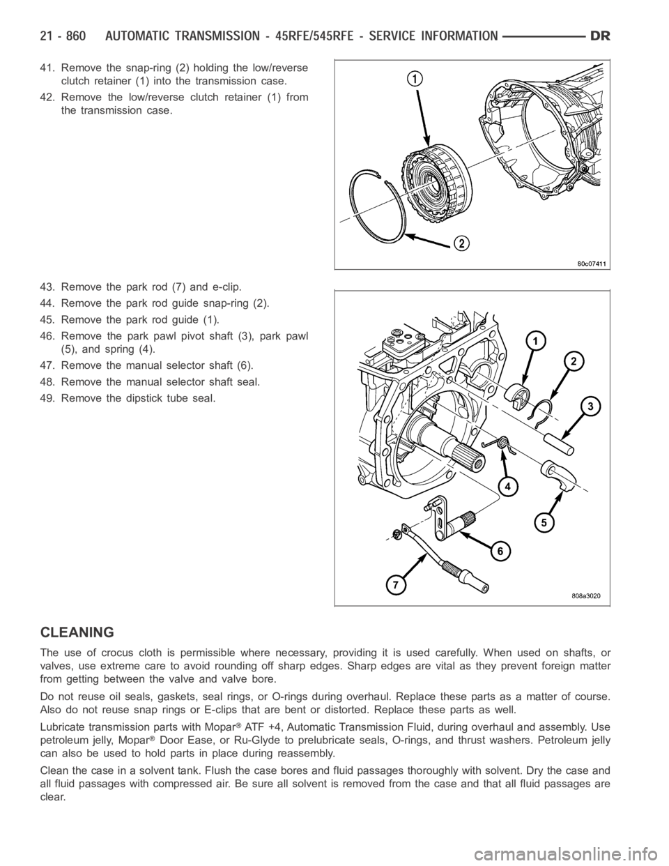
41. Remove the snap-ring (2) holding the low/reverse
clutch retainer (1) into the transmission case.
42. Remove the low/reverse clutch retainer (1) from
the transmission case.
43. Remove the park rod (7) and e-clip.
44. Remove the park rod guide snap-ring (2).
45. Remove the park rod guide (1).
46. Remove the park pawl pivot shaft (3), park pawl
(5), and spring (4).
47. Remove the manual selector shaft (6).
48. Remove the manual selector shaft seal.
49. Remove the dipstick tube seal.
CLEANING
The use of crocus cloth is permissible where necessary, providing it is usedcarefully.Whenusedonshafts,or
valves, use extreme care to avoid rounding off sharp edges. Sharp edges arevital as they prevent foreign matter
from getting between the valve and valve bore.
Do not reuse oil seals, gaskets, seal rings, or O-rings during overhaul. Replace these parts as a matter of course.
Also do not reuse snap rings or E-clips that are bent or distorted. Replace these parts as well.
Lubricate transmission parts with Mopar
ATF +4, Automatic Transmission Fluid, during overhaul and assembly. Use
petroleum jelly, Mopar
Door Ease, or Ru-Glyde to prelubricate seals, O-rings, and thrust washers. Petroleum jelly
canalsobeusedtoholdpartsinplaceduringreassembly.
Clean the case in a solvent tank. Flush the case bores and fluid passages thoroughly with solvent. Dry the case and
all fluid passages with compressed air. Be sure all solvent is removed fromthe case and that all fluid passages are
clear.
Page 3384 of 5267
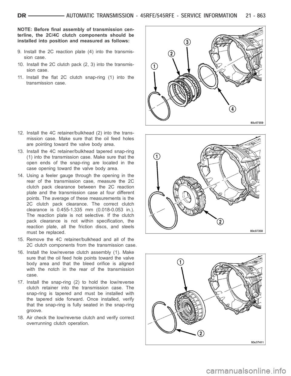
NOTE: Before final assembly of transmission cen-
terline, the 2C/4C clutch components should be
installed into position and measured as follows:
9. Install the 2C reaction plate (4) into the transmis-
sion case.
10. Install the 2C clutch pack (2, 3) into the transmis-
sion case.
11. Install the flat 2C clutchsnap-ring(1)intothe
transmission case.
12. Install the 4C retainer/bulkhead (2) into the trans-
mission case. Make sure that the oil feed holes
are pointing toward the valve body area.
13. Install the 4C retainer/bulkhead tapered snap-ring
(1) into the transmission case. Make sure that the
open ends of the snap-ring are located in the
case opening toward the valve body area.
14. Using a feeler gauge through the opening in the
rear of the transmission case, measure the 2C
clutch pack clearance between the 2C reaction
plate and the transmission case at four different
points. The average of these measurements is the
2C clutch pack clearance. The correct clutch
clearance is 0.455-1.335 mm (0.018-0.053 in.).
The reaction plate is not selective. If the clutch
pack clearance is not within specification, the
reaction plate, all the friction discs, and steels
must be replaced.
15. Remove the 4C retainer/bulkhead and all of the
2C clutch components from the transmission case.
16. Install the low/reverse clutch assembly (1). Make
sure that the oil feed hole points toward the valve
body area and that the bleed orifice is aligned
with the notch in the rear of the transmission
case.
17. Install the snap-ring (2) to hold the low/reverse
clutch retainer into the transmission case. The
snap-ring is tapered and must be installed with
the tapered side forward. Once installed, verify
that the snap-ring is fully seated in the snap-ring
groove.
18. Air check the low/reverse clutch and verify correct
overrunning clutch operation.