2006 DODGE RAM SRT-10 clutch
[x] Cancel search: clutchPage 3482 of 5267
CONVERTER-TORQUE
DESCRIPTION
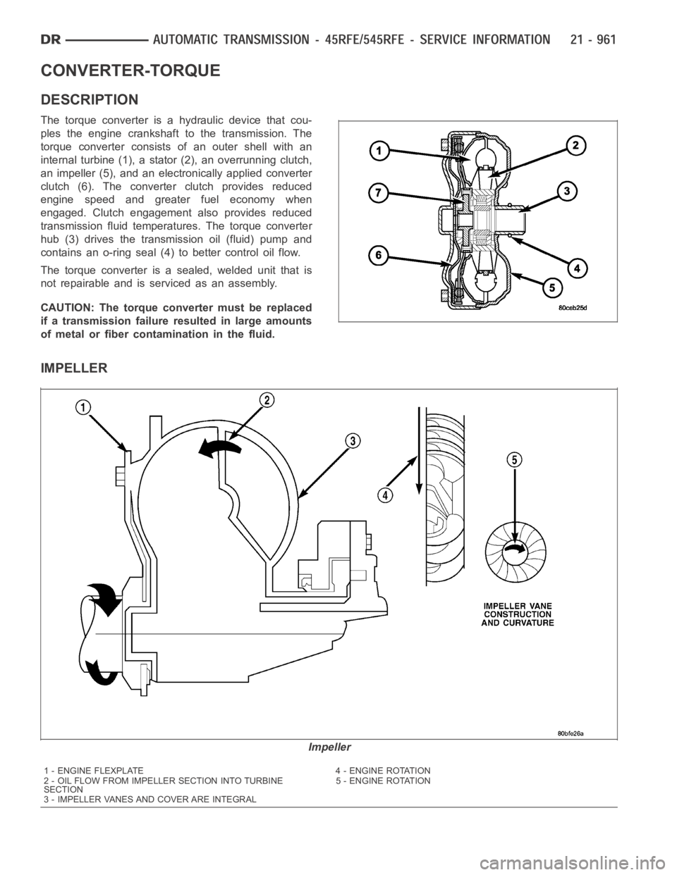
The torque converter is a hydraulic device that cou-
ples the engine crankshaft to the transmission. The
torque converter consists of an outer shell with an
internal turbine (1), a stator (2), an overrunning clutch,
an impeller (5), and an electronically applied converter
clutch (6). The converterclutch provides reduced
engine speed and greater fuel economy when
engaged. Clutch engagement also provides reduced
transmission fluid temperatures. The torque converter
hub (3) drives the transmission oil (fluid) pump and
contains an o-ring seal (4) to better control oil flow.
The torque converter is a sealed, welded unit that is
not repairable and is serviced as an assembly.
CAUTION: The torque converter must be replaced
if a transmission failure resulted in large amounts
of metal or fiber contamination in the fluid.
IMPELLER
Impeller
1 - ENGINE FLEXPLATE 4 - ENGINE ROTATION
2 - OIL FLOW FROM IMPELLER SECTION INTO TURBINE
SECTION5 - ENGINE ROTATION
3 - IMPELLER VANES AND COVER ARE INTEGRAL
Page 3484 of 5267
STATOR
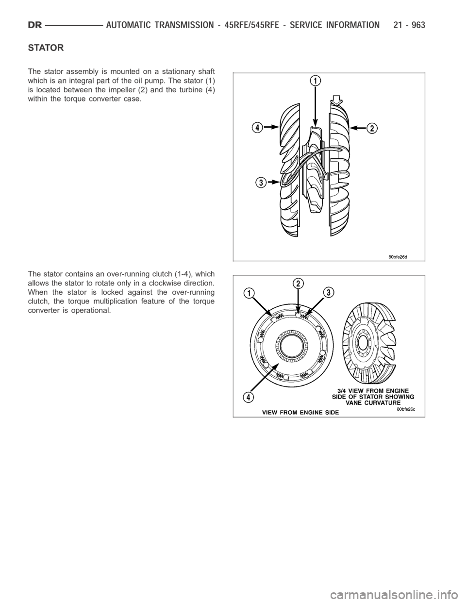
The stator assembly is mounted on a stationary shaft
which is an integral part of the oil pump. The stator (1)
islocatedbetweentheimpeller (2) and the turbine (4)
within the torque converter case.
The stator contains an over-running clutch (1-4), which
allows the stator to rotate only in a clockwise direction.
When the stator is locked against the over-running
clutch, the torque multiplication feature of the torque
converter is operational.
Page 3485 of 5267
TORQUE CONVERTER CLUTCH (TCC)
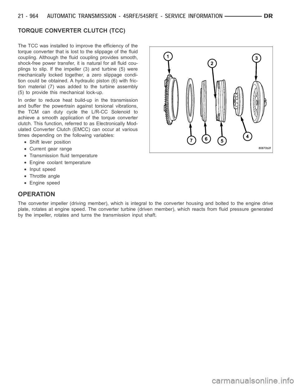
The TCC was installed to improve the efficiency of the
torque converter that is lost to the slippage of the fluid
coupling. Although the fluid coupling provides smooth,
shock-free power transfer, it is natural for all fluid cou-
plings to slip. If the impeller (3) and turbine (5) were
mechanically locked together, a zero slippage condi-
tion could be obtained. A hydraulic piston (6) with fric-
tion material (7) was added to the turbine assembly
(5) to provide this mechanical lock-up.
In order to reduce heat build-up in the transmission
and buffer the powertrain against torsional vibrations,
the TCM can duty cycle the L/R-CC Solenoid to
achieve a smooth application of the torque converter
clutch. This function, referred to as Electronically Mod-
ulated Converter Clutch (EMCC) can occur at various
times depending on the following variables:
Shift lever position
Current gear range
Transmission fluid temperature
Engine coolant temperature
Input speed
Throttle angle
Engine speed
OPERATION
The converter impeller (driving member), which is integral to the converter housing and bolted to the engine drive
plate, rotates at engine speed. The converter turbine (driven member), which reacts from fluid pressure generated
by the impeller, rotates and turns the transmission input shaft.
Page 3486 of 5267
TURBINE
As the fluid that was put into motion bythe impeller blades strikes the blades of the turbine, some of the energy and
rotational force is transferred into the turbine and the input shaft. Thiscauses both of them (turbine and input shaft)
to rotate in a clockwise direction following the impeller. As the fluid is leaving the trailing edges of the turbine’s
blades it continues in a “hindering” direction back toward the impeller. If the fluid is not redirected before it strikes
the impeller, it will strike the impeller in such a direction that it would tend to slow it down.
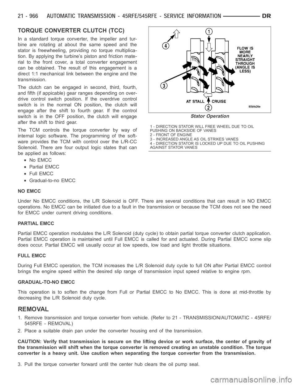
STATOR
Torque multiplication is achieved by locking the stator’s over-running clutch to its shaft. Under stall conditions (the
turbine is stationary), the oil leaving the turbine blades strikes the face of the stator blades and tries to rotate them
in a counterclockwise direction. When this happens the over-running clutch of the stator locks and holds the stator
from rotating. With the stator locked, the oil strikes the stator blades and is redirected into a “helping” direction
before it enters the impeller. This circulation of oil from impeller to turbine, turbine to stator, and stator to impeller,
can produce a maximum torque multiplicationofabout2.4:1.Astheturbinebegins to match the speed of the impel-
ler, the fluid that was hitting the stator in such as way as to cause it to lock-up is no longer doing so. In this con-
dition of operation, the stator begins to free wheel and the converter actsas a fluid coupling.
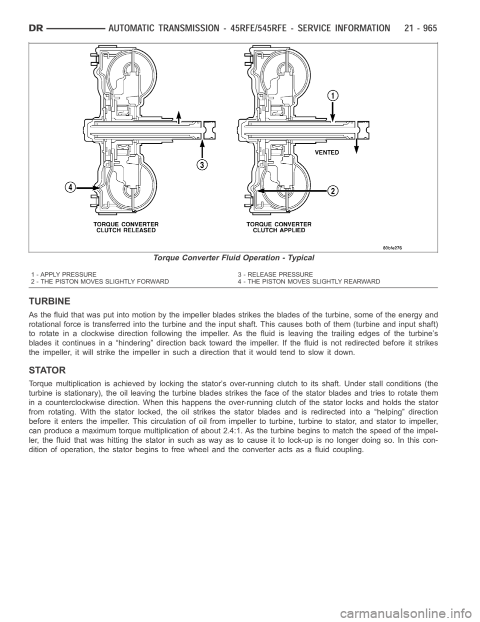
Torque Converter Fluid Operation - Typical
1 - APPLY PRESSURE 3 - RELEASE PRESSURE
2 - THE PISTON MOVES SLIGHTLY FORWARD 4 - THE PISTON MOVES SLIGHTLY REARWARD
Page 3487 of 5267
TORQUE CONVERTER CLUTCH (TCC)
In a standard torque converter, the impeller and tur-
bine are rotating at about the same speed and the
stator is freewheeling, providing no torque multiplica-
tion. By applying the turbine’s piston and friction mate-
rial to the front cover, a total converter engagement
can be obtained. The result of this engagement is a
direct 1:1 mechanical link between the engine and the
transmission.
The clutch can be engaged in second, third, fourth,
and fifth (if appicable) gear ranges depending on over-
drive control switch position. If the overdrive control
switch is in the normal ON position, the clutch will
engage after the shift to fourth gear. If the control
switch is in the OFF position, the clutch will engage
after the shift to third gear.
The TCM controls the torque converter by way of
internal logic software. The programming of the soft-
ware provides the TCM with control over the L/R-CC
Solenoid. There are four output logic states that can
be applied as follows:
No EMCC
Partial EMCC
Full EMCC
Gradual-to-no EMCC
NO EMCC
Under No EMCC conditions, the L/R Solenoid is OFF. There are several conditions that can result in NO EMCC
operations. No EMCC can be initiated due to a fault in the transmission or because the TCM does not see the need
for EMCC under current driving conditions.
PARTIAL EMCC
Partial EMCC operation modulates the L/R Solenoid (duty cycle) to obtain partial torque converter clutch application.
Partial EMCC operation is maintaineduntil Full EMCC is called for and actuated. During Partial EMCC some slip
does occur. Partial EMCC will usually occur at low speeds, low load and light throttle situations.
FULL EMCC
During Full EMCC operation, the TCM increases the L/R Solenoid duty cycle to full ON after Partial EMCC control
brings the engine speed within the desired slip range of transmission input speed relative to engine rpm.
GRADUAL-TO-NO EMCC
This operation is to soften the change from Full or Partial EMCC to No EMCC. This is done at mid-throttle by
decreasing the L/R Solenoid duty cycle.
REMOVAL
1. Remove transmission and torque converter from vehicle. (Refer to 21 - TRANSMISSION/AUTOMATIC - 45RFE/
545RFE - REMOVAL)
2. Place a suitable drain pan under the converter housing end of the transmission.
CAUTION: Verify that transmission is secure on the lifting device or work surface, the center of gravity of
the transmission will shift when the torque converter is removed creatingan unstable condition. The torque
converter is a heavy unit. Use caution when separating the torque converter from the transmission.
3. Pull the torque converter forward until the center hub clears the oil pumpseal.
Stator Operation
1 - DIRECTION STATOR WILL FREE WHEEL DUE TO OIL
PUSHING ON BACKSIDE OF VANES
2-FRONTOFENGINE
3 - INCREASED ANGLE AS OIL STRIKES VANES
4 - DIRECTION STATOR IS LOCKED UP DUE TO OIL PUSHING
AGAINST STATOR VANES
Page 3491 of 5267
ASSEMBLY-TRANSMISSION SOLENOID/TRS
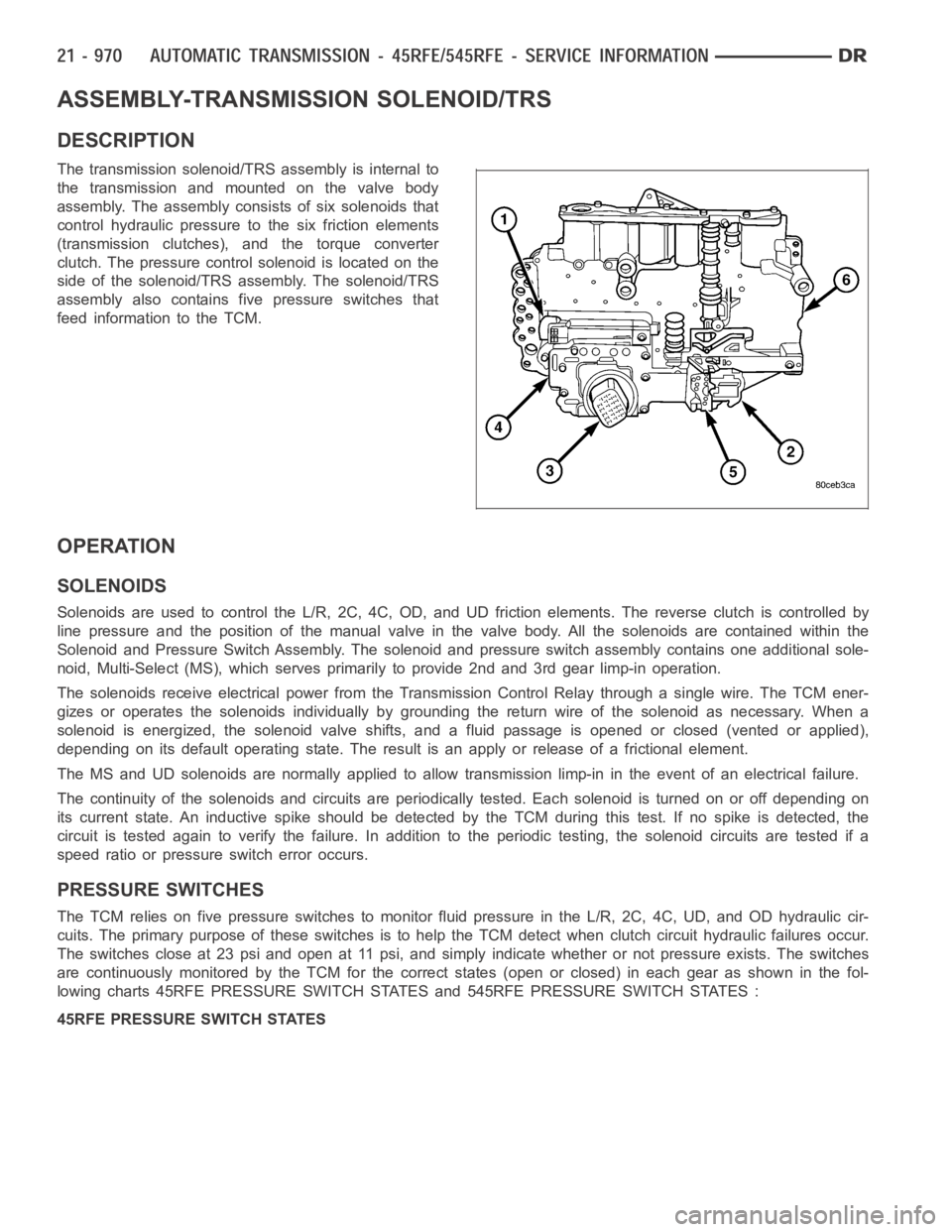
DESCRIPTION
The transmission solenoid/TRS assembly is internal to
the transmission and mounted on the valve body
assembly. The assembly consists of six solenoids that
control hydraulic pressure to the six friction elements
(transmission clutches), and the torque converter
clutch. The pressure control solenoid is located on the
side of the solenoid/TRS assembly. The solenoid/TRS
assembly also contains five pressure switches that
feed information to the TCM.
OPERATION
SOLENOIDS
Solenoids are used to control the L/R, 2C, 4C, OD, and UD friction elements.The reverse clutch is controlled by
line pressure and the position of the manual valve in the valve body. All thesolenoids are contained within the
Solenoid and Pressure Switch Assembly. The solenoid and pressure switch assembly contains one additional sole-
noid, Multi-Select (MS), which serves primarily to provide 2nd and 3rd gear limp-in operation.
The solenoids receive electrical power from the Transmission Control Relay through a single wire. The TCM ener-
gizes or operates the solenoids individually by grounding the return wireof the solenoid as necessary. When a
solenoid is energized, the solenoid valve shifts, and a fluid passage is opened or closed (vented or applied),
depending on its default operating state. The result is an apply or releaseof a frictional element.
The MS and UD solenoids are normallyapplied to allow transmission limp-inin the event of an electrical failure.
The continuity of the solenoids and circuits are periodically tested. Each solenoid is turned on or off depending on
its current state. An inductive spike should be detected by the TCM during this test. If no spike is detected, the
circuit is tested again to verify the failure. In addition to the periodic testing, the solenoid circuits are tested if a
speed ratio or pressure switch error occurs.
PRESSURE SWITCHES
The TCM relies on five pressure switches to monitor fluid pressure in the L/R, 2C, 4C, UD, and OD hydraulic cir-
cuits. The primary purpose of these switches is to help the TCM detect when clutch circuit hydraulic failures occur.
The switches close at 23 psi and open at 11 psi, and simply indicate whether or not pressure exists. The switches
are continuously monitored by the TCM for the correct states (open or closed) in each gear as shown in the fol-
lowing charts 45RFE PRESSURE SWITCH STATES and 545RFE PRESSURE SWITCH STATES :
45RFE PRESSURE SWITCH STATES
Page 3495 of 5267
BODY-VALVE
DESCRIPTION
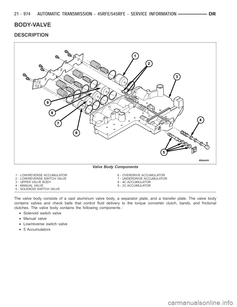
The valve body consists of a cast aluminum valve body, a separator plate, and a transfer plate. The valve body
contains valves and check balls that control fluid delivery to the torque converter clutch, bands, and frictional
clutches. The valve body contains the following components :
Solenoid switch valve
Manual valve
Low/reverse switch valve
5 Accumulators
Valve Body Components
1 - LOW/REVERSE ACCUMULATOR 6 - OVERDRIVE ACCUMULATOR
2 - LOW/REVERSE SWITCH VALVE 7 - UNDERDRIVE ACCUMULATOR
3 - UPPER VALVE BODY 8 - 4C ACCUMULATOR
4 - MANUAL VALVE 9 - 2C ACCUMULATOR
5 - SOLENOID SWITCH VALVE
Page 3496 of 5267
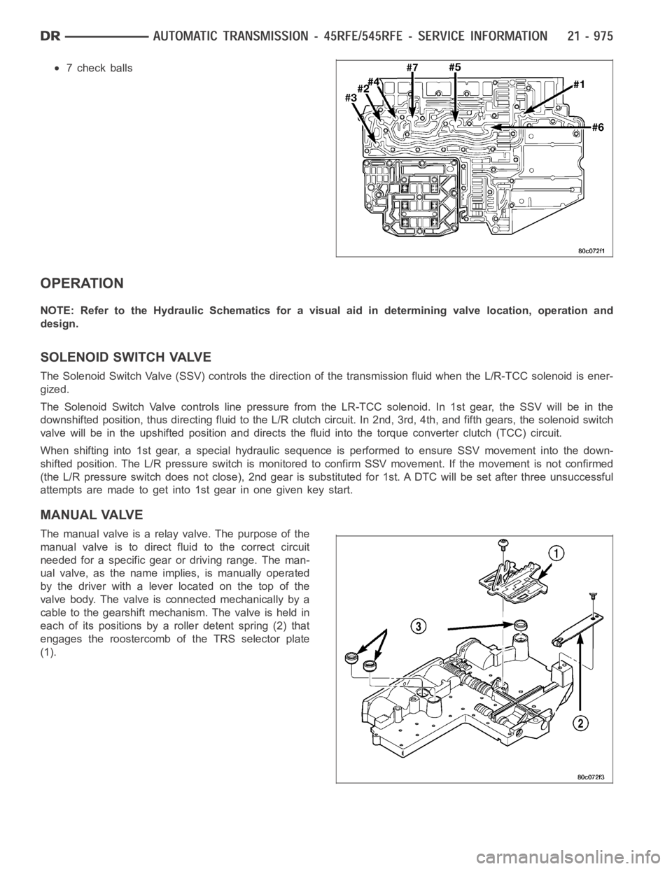
7 check balls
OPERATION
NOTE: Refer to the Hydraulic Schematics for a visual aid in determining valve location, operation and
design.
SOLENOID SWITCH VALVE
The Solenoid Switch Valve (SSV) controls the direction of the transmission fluid when the L/R-TCC solenoid is ener-
gized.
The Solenoid Switch Valve controls line pressure from the LR-TCC solenoid. In 1st gear, the SSV will be in the
downshifted position, thus directing fluid to the L/R clutch circuit. In 2nd, 3rd, 4th, and fifth gears, the solenoid switch
valve will be in the upshifted position and directs the fluid into the torque converter clutch (TCC) circuit.
When shifting into 1st gear, a special hydraulic sequence is performed to ensure SSV movement into the down-
shifted position. The L/R pressure switch is monitored to confirm SSV movement. If the movement is not confirmed
(the L/R pressure switch does not close), 2nd gear is substituted for 1st. ADTC will be set after three unsuccessful
attempts are made to get into 1st gear in one given key start.
MANUAL VALVE
The manual valve is a relay valve. The purpose of the
manual valve is to direct fluid to the correct circuit
needed for a specific gear or driving range. The man-
ual valve, as the name implies, is manually operated
by the driver with a lever located on the top of the
valve body. The valve is connected mechanically by a
cable to the gearshift mechanism. The valve is held in
each of its positions by a roller detent spring (2) that
engages the roostercomb of the TRS selector plate
(1).