2006 DODGE RAM SRT-10 tire pressure
[x] Cancel search: tire pressurePage 4323 of 5267
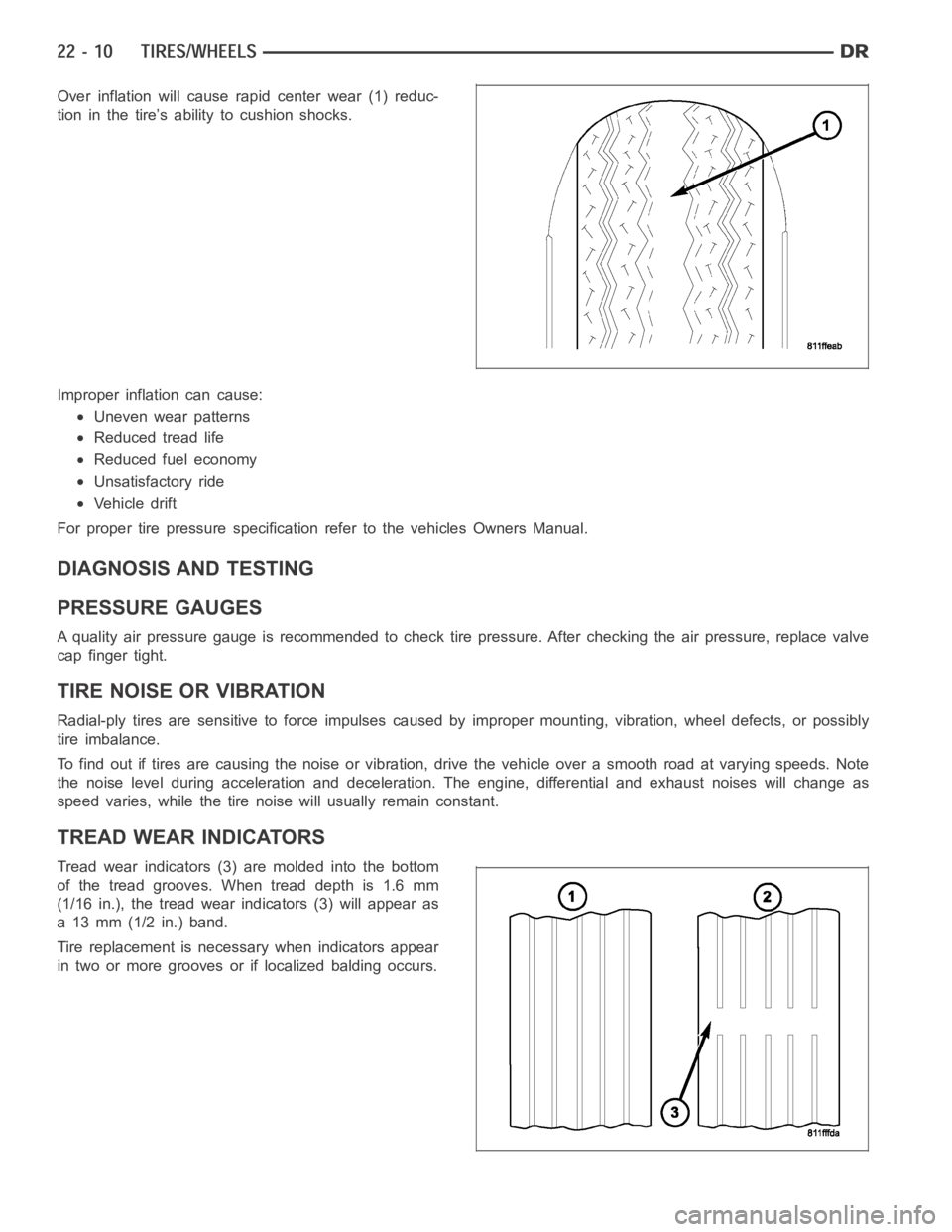
Over inflation will cause rapid center wear (1) reduc-
tion in the tire’s ability to cushion shocks.
Improper inflation can cause:
Uneven wear patterns
Reduced tread life
Reduced fuel economy
Unsatisfactory ride
Vehicle drift
For proper tire pressure specification refer to the vehicles Owners Manual.
DIAGNOSIS AND TESTING
PRESSURE GAUGES
A quality air pressure gauge is recommended to check tire pressure. After checking the air pressure, replace valve
cap finger tight.
TIRE NOISE OR VIBRATION
Radial-ply tires are sensitive to force impulses caused by improper mounting, vibration, wheel defects, or possibly
tire imbalance.
To find out if tires are causing the noise or vibration, drive the vehicle over a smooth road at varying speeds. Note
the noise level during acceleration and deceleration. The engine, differential and exhaust noises will change as
speed varies, while the tire noise will usually remain constant.
TREAD WEAR INDICATORS
Tread wear indicators (3) are molded into the bottom
of the tread grooves. When tread depth is 1.6 mm
(1/16 in.), the tread wear indicators (3) will appear as
a 13 mm (1/2 in.) band.
Tire replacement is necessary when indicators appear
in two or more grooves or if localized balding occurs.
Page 4329 of 5267
WHEEL DESIGN
The rim size is on the vehicle safety certification label
located on the drivers door shut face. The size of the
rim is determined by the drivetrain package. Original
equipment wheels/rims are designed for operation up
to the specified maximum vehicle capacity.
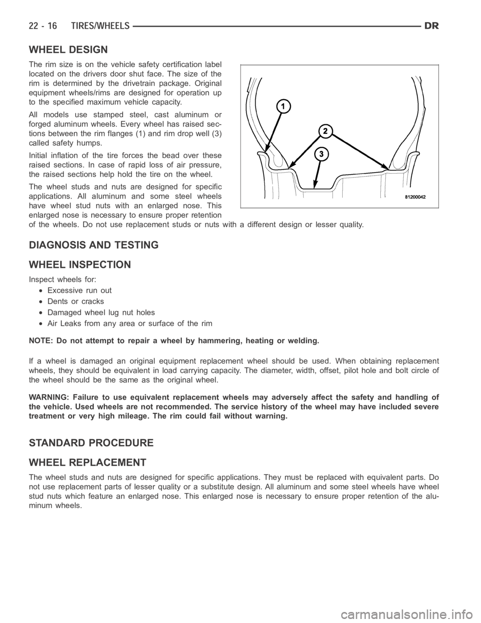
All models use stamped steel, cast aluminum or
forged aluminum wheels. Every wheel has raised sec-
tions between the rim flanges (1) and rim drop well (3)
called safety humps.
Initial inflation of the tire forces the bead over these
raised sections. In case of rapid loss of air pressure,
the raised sections help hold the tire on the wheel.
The wheel studs and nuts are designed for specific
applications. All aluminum and some steel wheels
have wheel stud nuts with an enlarged nose. This
enlarged nose is necessary to ensure proper retention
of the wheels. Do not use replacement studs or nuts with a different design orlesserquality.
DIAGNOSIS AND TESTING
WHEEL INSPECTION
Inspect wheels for:
Excessive run out
Dents or cracks
Damaged wheel lug nut holes
Air Leaks from any area or surface of the rim
NOTE: Do not attempt to repair a wheel by hammering, heating or welding.
If a wheel is damaged an original equipment replacement wheel should be used. When obtaining replacement
wheels, they should be equivalent in load carrying capacity. The diameter, width, offset, pilot hole and bolt circle of
the wheel should be the same as the original wheel.
WARNING: Failure to use equivalent replacement wheels may adversely affect the safety and handling of
the vehicle. Used wheels are not recommended. The service history of the wheel may have included severe
treatment or very high mileage. The rim could fail without warning.
STANDARD PROCEDURE
WHEEL REPLACEMENT
The wheel studs and nuts are designed for specific applications. They mustbe replaced with equivalent parts. Do
not use replacement parts of lesser quality or a substitute design. All aluminum and some steel wheels have wheel
stud nuts which feature an enlarged nose. This enlarged nose is necessary to ensure proper retention of the alu-
minum wheels.
Page 4425 of 5267
BODY SIDE MOLDINGS
REMOVAL
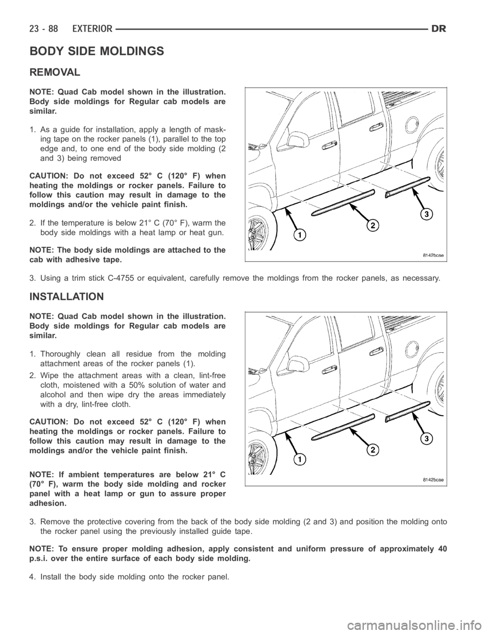
NOTE: Quad Cab model shown in the illustration.
Body side moldings for Regular cab models are
similar.
1. As a guide for installation, apply a length of mask-
ing tape on the rocker panels (1), parallel to the top
edge and, to one end of the body side molding (2
and 3) being removed
CAUTION: Do not exceed 52° C (120° F) when
heating the moldings or rocker panels. Failure to
follow this caution may result in damage to the
moldings and/or the vehicle paint finish.
2. If the temperature is below 21° C (70° F), warm the
body side moldings with a heat lamp or heat gun.
NOTE: The body side moldings are attached to the
cab with adhesive tape.
3. Using a trim stick C-4755 or equivalent, carefully remove the moldings from the rocker panels, as necessary.
INSTALLATION
NOTE: Quad Cab model shown in the illustration.
Body side moldings for Regular cab models are
similar.
1. Thoroughly clean all residue from the molding
attachment areas of the rocker panels (1).
2. Wipe the attachment areas with a clean, lint-free
cloth, moistened with a 50% solution of water and
alcohol and then wipe dry the areas immediately
with a dry, lint-free cloth.
CAUTION: Do not exceed 52° C (120° F) when
heating the moldings or rocker panels. Failure to
follow this caution may result in damage to the
moldings and/or the vehicle paint finish.
NOTE: If ambient temperatures are below 21° C
(70° F), warm the body side molding and rocker
panel with a heat lamp or gun to assure proper
adhesion.
3. Remove the protective covering from the back of the body side molding (2 and 3) and position the molding onto
the rocker panel using the previously installed guide tape.
NOTE: To ensure proper molding adhesion, apply consistent and uniform pressure of approximately 40
p.s.i. over the entire surface of each body side molding.
4. Install the body side molding onto the rocker panel.
Page 4431 of 5267
INSTALLATION
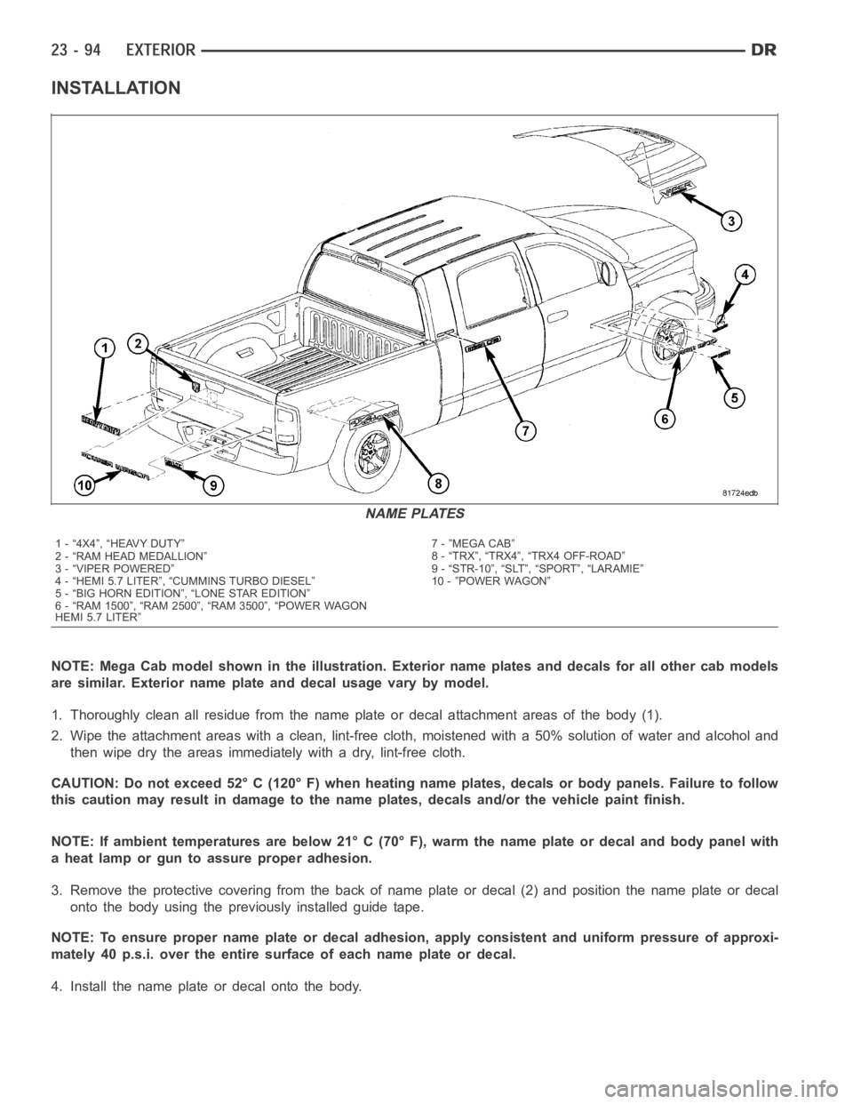
NOTE: Mega Cab model shown in the illustration. Exterior name plates and decals for all other cab models
are similar. Exterior name plate and decal usage vary by model.
1. Thoroughly clean all residue from the name plate or decal attachment areas of the body (1).
2. Wipe the attachment areas with a clean, lint-free cloth, moistened witha 50% solution of water and alcohol and
then wipe dry the areas immediately with a dry, lint-free cloth.
CAUTION: Do not exceed 52° C (120° F) when heating name plates, decals or body panels. Failure to follow
this caution may result in damage to the name plates, decals and/or the vehicle paint finish.
NOTE: If ambient temperatures are below 21° C (70° F), warm the name plate ordecal and body panel with
a heat lamp or gun to assure proper adhesion.
3. Remove the protective covering from the back of name plate or decal (2) and position the name plate or decal
onto the body using the previously installed guide tape.
NOTE: To ensure proper name plate or decal adhesion, apply consistent and uniform pressure of approxi-
mately 40 p.s.i. over the entire surface of each name plate or decal.
4. Install the name plate or decal onto the body.
NAME PLATES
1 - “4X4”, “HEAVY DUTY”
2 - “RAM HEAD MEDALLION”
3 - “VIPER POWERED”
4 - “HEMI 5.7 LITER”, “CUMMINS TURBO DIESEL”
5 - “BIG HORN EDITION”, “LONE STAR EDITION”
6 - “RAM 1500”, “RAM 2500”, “RAM 3500”, “POWER WAGON
HEMI 5.7 LITER”7 - ”MEGA CAB”
8 - “TRX”, “TRX4”, “TRX4 OFF-ROAD”
9 - “STR-10”, “SLT”, “SPORT”, “LARAMIE”
10 - ”POWER WAGON”
Page 4450 of 5267
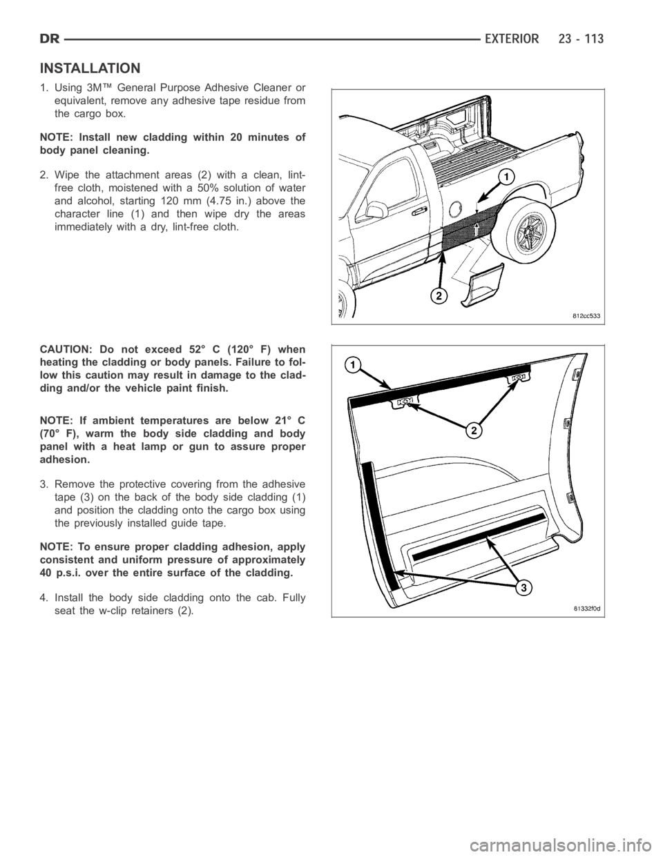
INSTALLATION
1. Using 3M™ General Purpose Adhesive Cleaner or
equivalent, remove any adhesive tape residue from
the cargo box.
NOTE: Install new cladding within 20 minutes of
body panel cleaning.
2. Wipe the attachment areas (2) with a clean, lint-
free cloth, moistened with a 50% solution of water
and alcohol, starting 120 mm (4.75 in.) above the
character line (1) and then wipe dry the areas
immediately with a dry, lint-free cloth.
CAUTION: Do not exceed 52° C (120° F) when
heating the cladding or body panels. Failure to fol-
low this caution may result in damage to the clad-
ding and/or the vehicle paint finish.
NOTE: If ambient temperatures are below 21° C
(70° F), warm the body side cladding and body
panel with a heat lamp or gun to assure proper
adhesion.
3. Remove the protective covering from the adhesive
tape (3) on the back of the body side cladding (1)
and position the cladding onto the cargo box using
the previously installed guide tape.
NOTE: To ensure proper cladding adhesion, apply
consistent and uniform pressure of approximately
40 p.s.i. over the entire surface of the cladding.
4. Install the body side cladding onto the cab. Fully
seat the w-clip retainers (2).
Page 4453 of 5267
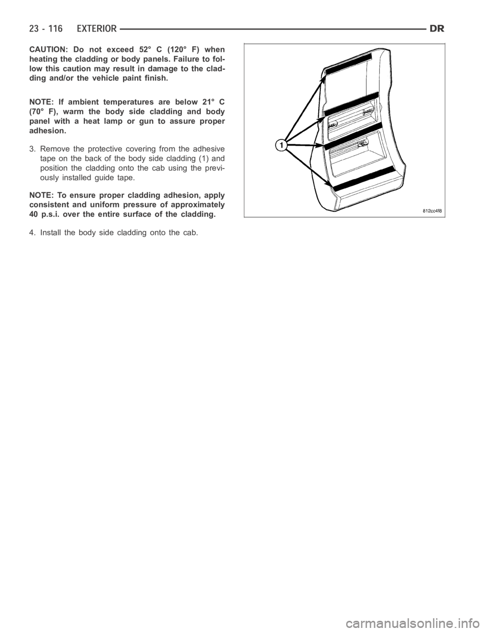
CAUTION: Do not exceed 52° C (120° F) when
heating the cladding or body panels. Failure to fol-
low this caution may result in damage to the clad-
ding and/or the vehicle paint finish.
NOTE: If ambient temperatures are below 21° C
(70° F), warm the body side cladding and body
panel with a heat lamp or gun to assure proper
adhesion.
3. Remove the protective covering from the adhesive
tape on the back of the body side cladding (1) and
position the cladding onto the cab using the previ-
ously installed guide tape.
NOTE: To ensure proper cladding adhesion, apply
consistent and uniform pressure of approximately
40 p.s.i. over the entire surface of the cladding.
4. Install the body side cladding onto the cab.
Page 4455 of 5267
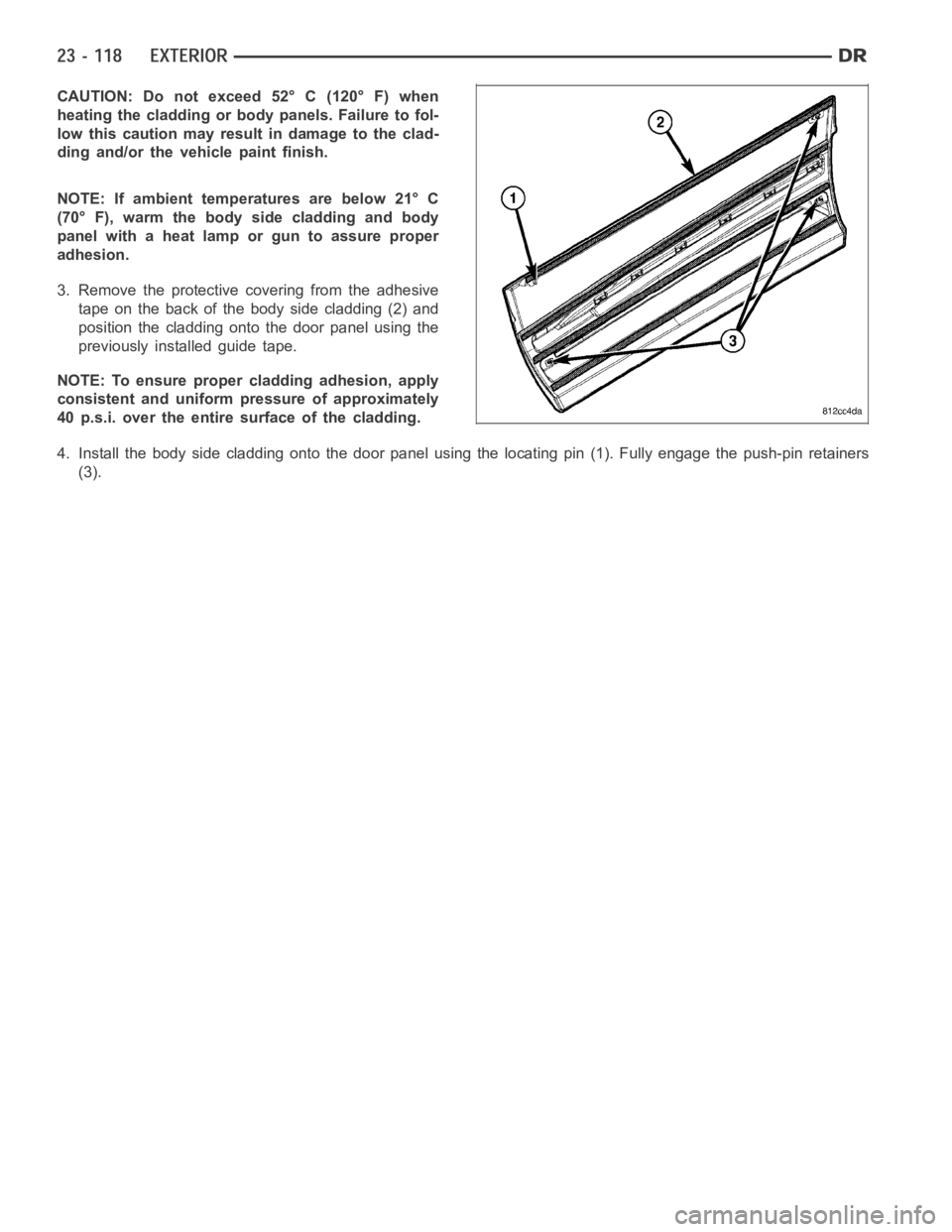
CAUTION: Do not exceed 52° C (120° F) when
heating the cladding or body panels. Failure to fol-
low this caution may result in damage to the clad-
ding and/or the vehicle paint finish.
NOTE: If ambient temperatures are below 21° C
(70° F), warm the body side cladding and body
panel with a heat lamp or gun to assure proper
adhesion.
3. Remove the protective covering from the adhesive
tape on the back of the body side cladding (2) and
position the cladding onto the door panel using the
previously installed guide tape.
NOTE: To ensure proper cladding adhesion, apply
consistent and uniform pressure of approximately
40 p.s.i. over the entire surface of the cladding.
4. Install the body side cladding onto the door panel using the locating pin(1). Fully engage the push-pin retainers
(3).
Page 4456 of 5267
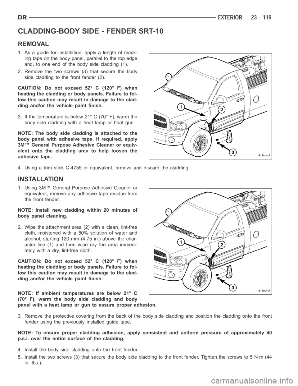
CLADDING-BODY SIDE - FENDER SRT-10
REMOVAL
1. As a guide for installation, apply a length of mask-
ing tape on the body panel, parallel to the top edge
and, to one end of the body side cladding (1).
2. Remove the two screws (3) that secure the body
side cladding to the front fender (2).
CAUTION: Do not exceed 52° C (120° F) when
heating the cladding or body panels. Failure to fol-
low this caution may result in damage to the clad-
ding and/or the vehicle paint finish.
3. If the temperature is below 21° C (70° F), warm the
body side cladding with a heat lamp or heat gun.
NOTE: The body side cladding is attached to the
body panel with adhesive tape. If required, apply
3M™ General Purpose Adhesive Cleaner or equiv-
alent onto the cladding area to help loosen the
adhesive tape.
4. Using a trim stick C-4755 or equivalent, remove and discard the cladding.
INSTALLATION
1. Using 3M™ General Purpose Adhesive Cleaner or
equivalent, remove any adhesive tape residue from
the front fender.
NOTE: Install new cladding within 20 minutes of
body panel cleaning.
2. Wipe the attachment area (2) with a clean, lint-free
cloth, moistened with a 50% solution of water and
alcohol, starting 120 mm (4.75 in.) above the char-
acterline(1)andthenwipedrytheareaimmedi-
ately with a dry, lint-free cloth.
CAUTION: Do not exceed 52° C (120° F) when
heating the cladding or body panels. Failure to fol-
low this caution may result in damage to the clad-
ding and/or the vehicle paint finish.
NOTE: If ambient temperatures are below 21° C
(70° F), warm the body side cladding and body
panel with a heat lamp or gun to assure proper adhesion.
3. Remove the protective covering from the back of the body side cladding and position the cladding onto the front
fender using the previously installed guide tape.
NOTE: To ensure proper cladding adhesion, apply consistent and uniform pressure of approximately 40
p.s.i. over the entire surface of the cladding.
4. Install the body side cladding onto the front fender.
5. Install the two screws (3) that secure the body side cladding to the frontfender. Tighten the screws to 5 Nꞏm (44
in. lbs.).