2006 DODGE RAM SRT-10 tire pressure
[x] Cancel search: tire pressurePage 118 of 5267
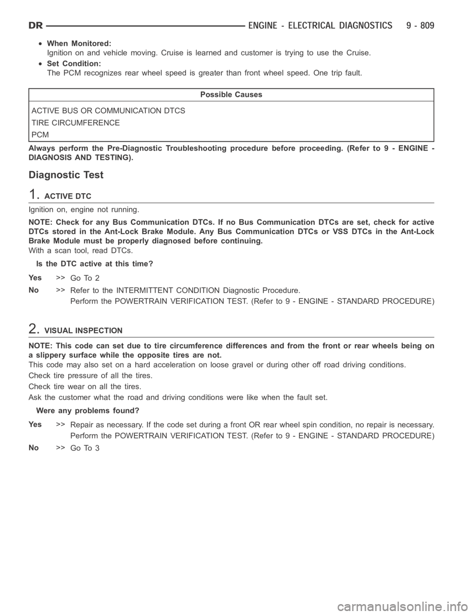
When Monitored:
Ignition on and vehicle moving. Cruise is learned and customer is trying touse the Cruise.
Set Condition:
The PCM recognizes rear wheel speed is greater than front wheel speed. One trip fault.
Possible Causes
ACTIVE BUS OR COMMUNICATION DTCS
TIRE CIRCUMFERENCE
PCM
Always perform the Pre-Diagnostic Troubleshooting procedure before proceeding. (Refer to 9 - ENGINE -
DIAGNOSIS AND TESTING).
Diagnostic Test
1.ACTIVE DTC
Ignition on, engine not running.
NOTE: Check for any Bus Communication DTCs. If no Bus Communication DTCs are set, check for active
DTCs stored in the Ant-Lock Brake Module. Any Bus Communication DTCs or VSSDTCs in the Ant-Lock
Brake Module must be properly diagnosed before continuing.
With a scan tool, read DTCs.
Is the DTC active at this time?
Ye s>>
Go To 2
No>>
Refer to the INTERMITTENT CONDITION Diagnostic Procedure.
Perform the POWERTRAIN VERIFICATION TEST. (Refer to 9 - ENGINE - STANDARD PROCEDURE)
2.VISUAL INSPECTION
NOTE: This code can set due to tire circumference differences and from the front or rear wheels being on
a slippery surface while the opposite tires are not.
This code may also set on a hard acceleration on loose gravel or during otheroff road driving conditions.
Check tire pressure of all the tires.
Checktirewearonallthetires.
Ask the customer what the road and driving conditions were like when the fault set.
Were any problems found?
Ye s>>
Repair as necessary. If the code set during a front OR rear wheel spin condition, no repair is necessary.
Perform the POWERTRAIN VERIFICATION TEST. (Refer to 9 - ENGINE - STANDARD PROCEDURE)
No>>
Go To 3
Page 121 of 5267
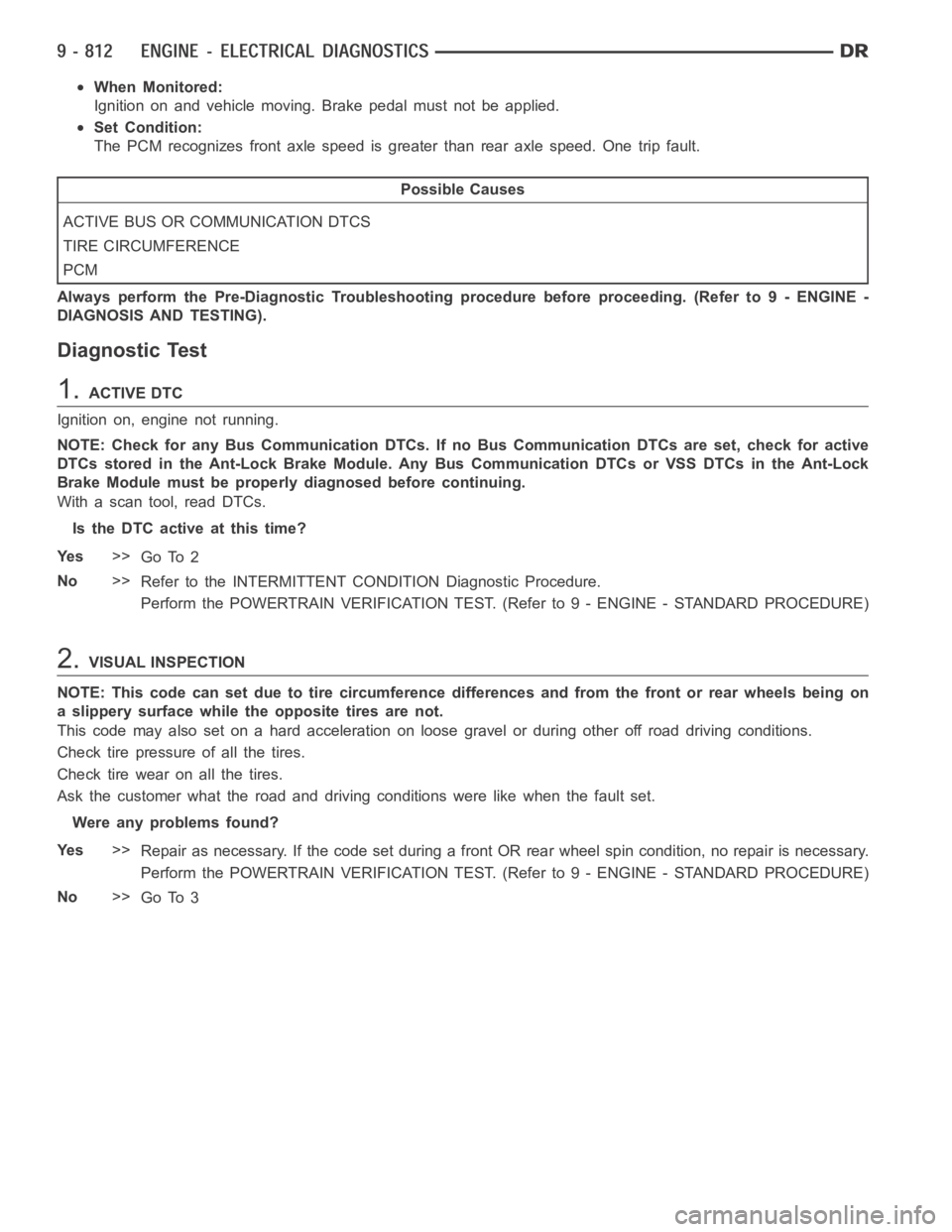
When Monitored:
Ignition on and vehicle moving. Brake pedal must not be applied.
Set Condition:
The PCM recognizes front axle speed is greater than rear axle speed. One tripfault.
Possible Causes
ACTIVE BUS OR COMMUNICATION DTCS
TIRE CIRCUMFERENCE
PCM
Always perform the Pre-Diagnostic Troubleshooting procedure before proceeding. (Refer to 9 - ENGINE -
DIAGNOSIS AND TESTING).
Diagnostic Test
1.ACTIVE DTC
Ignition on, engine not running.
NOTE: Check for any Bus Communication DTCs. If no Bus Communication DTCs are set, check for active
DTCs stored in the Ant-Lock Brake Module. Any Bus Communication DTCs or VSSDTCs in the Ant-Lock
Brake Module must be properly diagnosed before continuing.
With a scan tool, read DTCs.
Is the DTC active at this time?
Ye s>>
Go To 2
No>>
Refer to the INTERMITTENT CONDITION Diagnostic Procedure.
Perform the POWERTRAIN VERIFICATION TEST. (Refer to 9 - ENGINE - STANDARD PROCEDURE)
2.VISUAL INSPECTION
NOTE: This code can set due to tire circumference differences and from the front or rear wheels being on
a slippery surface while the opposite tires are not.
This code may also set on a hard acceleration on loose gravel or during otheroff road driving conditions.
Check tire pressure of all the tires.
Checktirewearonallthetires.
Ask the customer what the road and driving conditions were like when the fault set.
Were any problems found?
Ye s>>
Repair as necessary. If the code set during a front OR rear wheel spin condition, no repair is necessary.
Perform the POWERTRAIN VERIFICATION TEST. (Refer to 9 - ENGINE - STANDARD PROCEDURE)
No>>
Go To 3
Page 264 of 5267
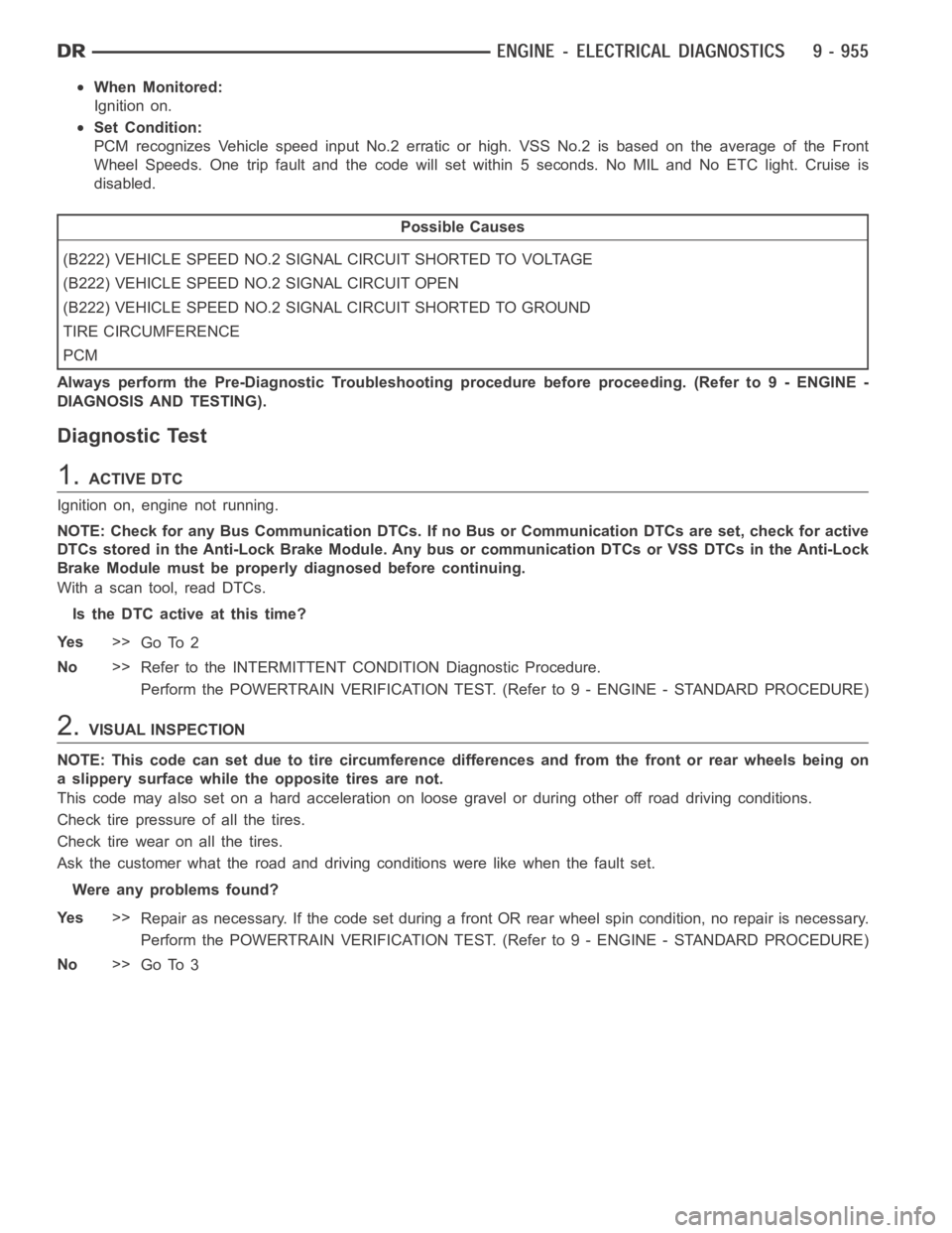
When Monitored:
Ignition on.
Set Condition:
PCM recognizes Vehicle speed input No.2 erratic or high. VSS No.2 is based on the average of the Front
Wheel Speeds. One trip fault and the code will set within 5 seconds. No MIL and No ETC light. Cruise is
disabled.
Possible Causes
(B222) VEHICLE SPEED NO.2 SIGNAL CIRCUIT SHORTED TO VOLTAGE
(B222) VEHICLE SPEED NO.2 SIGNAL CIRCUIT OPEN
(B222) VEHICLE SPEED NO.2 SIGNAL CIRCUIT SHORTED TO GROUND
TIRE CIRCUMFERENCE
PCM
Always perform the Pre-Diagnostic Troubleshooting procedure before proceeding. (Refer to 9 - ENGINE -
DIAGNOSIS AND TESTING).
Diagnostic Test
1.ACTIVE DTC
Ignition on, engine not running.
NOTE: Check for any Bus Communication DTCs. If no Bus or Communication DTCsare set, check for active
DTCs stored in the Anti-Lock Brake Module. Any bus or communication DTCs orVSS DTCs in the Anti-Lock
Brake Module must be properly diagnosed before continuing.
With a scan tool, read DTCs.
Is the DTC active at this time?
Ye s>>
Go To 2
No>>
Refer to the INTERMITTENT CONDITION Diagnostic Procedure.
Perform the POWERTRAIN VERIFICATION TEST. (Refer to 9 - ENGINE - STANDARD PROCEDURE)
2.VISUAL INSPECTION
NOTE: This code can set due to tire circumference differences and from the front or rear wheels being on
a slippery surface while the opposite tires are not.
This code may also set on a hard acceleration on loose gravel or during otheroff road driving conditions.
Check tire pressure of all the tires.
Checktirewearonallthetires.
Ask the customer what the road and driving conditions were like when the fault set.
Were any problems found?
Ye s>>
Repair as necessary. If the code set during a front OR rear wheel spin condition, no repair is necessary.
Perform the POWERTRAIN VERIFICATION TEST. (Refer to 9 - ENGINE - STANDARD PROCEDURE)
No>>
Go To 3
Page 895 of 5267
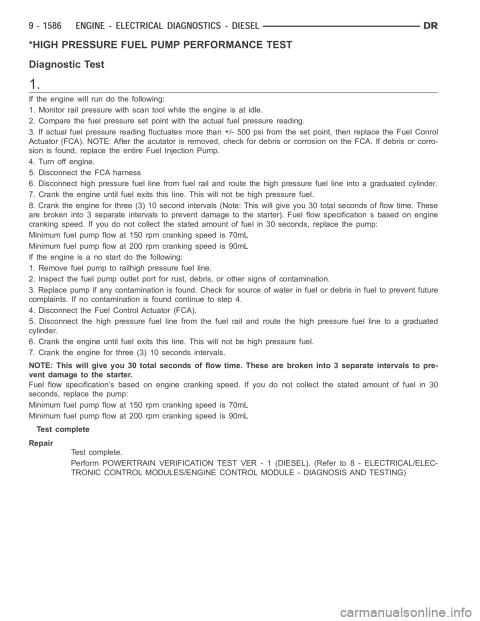
*HIGH PRESSURE FUEL PUMP PERFORMANCE TEST
Diagnostic Test
1.
If the engine will run do the following:
1. Monitor rail pressure with scan tool while the engine is at idle.
2. Compare the fuel pressure set point with the actual fuel pressure reading.
3. If actual fuel pressure reading fluctuates more than +/- 500 psi from theset point, then replace the Fuel Conrol
Actuator (FCA). NOTE: After the acutator is removed, check for debris or corrosion on the FCA. If debris or corro-
sion is found, replace the entire Fuel Injection Pump.
4. Turn off engine.
5. Disconnect the FCA harness
6. Disconnect high pressure fuel line from fuel rail and route the high pressure fuel line into a graduated cylinder.
7. Crank the engine until fuel exits this line. This will not be high pressurefuel.
8. Crank the engine for three (3) 10 second intervals (Note: This will give you 30 total seconds of flow time. These
are broken into 3 separate intervals to prevent damage to the starter). Fuel flow specification s based on engine
cranking speed. If you do not collect the stated amount of fuel in 30 seconds, replace the pump:
Minimum fuel pump flow at 150 rpm cranking speed is 70mL
Minimum fuel pump flow at 200 rpm cranking speed is 90mL
If the engine is a no start do the following:
1. Remove fuel pump to railhigh pressure fuel line.
2. Inspect the fuel pump outlet port for rust, debris, or other signs of contamination.
3. Replace pump if any contamination is found. Check for source of water in fuel or debris in fuel to prevent future
complaints. If no contamination is found continue to step 4.
4. Disconnect the Fuel Control Actuator (FCA).
5. Disconnect the high pressure fuel line from the fuel rail and route the high pressure fuel line to a graduated
cylinder.
6. Crank the engine until fuel exits this line. This will not be high pressurefuel.
7. Crank the engine for three (3) 10 seconds intervals.
NOTE: This will give you 30 total seconds of flow time. These are broken into3 separate intervals to pre-
vent damage to the starter.
Fuel flow specification’s based on engine cranking speed. If you do not collect the stated amount of fuel in 30
seconds, replace the pump:
Minimum fuel pump flow at 150 rpm cranking speed is 70mL
Minimum fuel pump flow at 200 rpm cranking speed is 90mL
Test complete
Repair
Te s t c o m p l e t e .
Perform POWERTRAIN VERIFICATION TEST VER - 1 (DIESEL). (Refer to 8 - ELECTRICAL/ELEC-
TRONIC CONTROL MODULES/ENGINE CONTROL MODULE - DIAGNOSIS AND TESTING)
Page 1587 of 5267
DIAGNOSIS AND TESTING
DIAGNOSIS AND TESTING - ENGINE OIL LEAK
Begin with a thorough visual inspection of the engine, particularly at thearea of the suspected leak. If an oil leak
source is not readily identifiable, thefollowingstepsshouldbefollowed:
1. Do not clean or degrease the engine at this time because some solvents maycause rubber to swell, temporarily
stopping the leak.
2. Add an oil soluble dye (use as recommended by manufacturer). Start the engine and let idle for approximately 15
minutes. Check the oil dipstick to make sure the dye is thoroughly mixed as indicated with a bright yellow color
under a black light.
3. Using a black light, inspect the entire engine for fluorescent dye, particularly at the suspected area of oil leak. If
the oil leak is found and identified, repair per service manual instructions.
4. If dye is not observed, drive the vehicle at various speeds for approximately 24 km (15 miles), and repeat inspec-
tion.If the oil leak source is not positively identified at this time, proceed with the air leak detection test method.
Air Leak Detection Test Method
1. Disconnect the breather cap to air cleaner hose at the breather cap end. Cap or plug breather cap nipple.
2. Remove the PCV valve from the cylinder head cover. Cap or plug the PCV valvegrommet.
3. Attach an air hose with pressure gauge and regulator to the dipstick tube.
CAUTION: Do not subject the engine assembly to more than 20.6 kPa (3 PSI) of test pressure.
4. Gradually apply air pressure from 1 psi to 2.5 psi maximum while applyingsoapy water at the suspected source.
Adjust the regulator to the suitable test pressure that provide the best bubbles which will pinpoint the leak
source. If the oil leak is detected and identified, repair per service manual procedures.
5. If the leakage occurs at the rear oil seal area, refer to the section, Inspection for Rear Seal Area Leak.
6. If no leaks are detected, turn off the air supply and remove the air hose and all plugs and caps. Install the PCV
valve and breather cap hose.
7. Clean the oil off the suspect oil leak area using a suitable solvent. Drive the vehicle at various speeds approx-
imately 24 km (15 miles). Inspect the engine for signs of an oil leak by usinga black light.
INSPECTION FOR REAR SEAL AREA LEAKS
Since it is sometimes difficult to determine the source of an oil leak in therear seal area of the engine, a more
involved inspection is necessary. The following steps should be followedto help pinpoint the source of the leak.
If the leakage occurs at the crankshaft rear oil seal area:
1. Disconnect the battery.
2. Raise the vehicle.
3. Remove torque converter or clutch housing cover and inspect rear of block for evidence of oil. Use a black light
to check for the oil leak:
a. Circular spray pattern generally indicates seal leakage or crankshaftdamage.
b. Where leakage tends to run straight down, possible causes are a porous block, oil galley pipe plugs, oil filter
runoff, and main bearing cap to cylinder block mating surfaces.
4. If no leaks are detected, pressurize the crankcase as outlined in the, Inspection (Engine oil Leaks in general)
CAUTION: Do not exceed 20.6 kPa (3 psi).
5. If the leak is not detected, very slowly turn the crankshaft and watch forleakage. If a leak is detected between
the crankshaft and seal while slowly turning the crankshaft, it is possible the crankshaft seal surface is damaged.
The seal area on the crankshaft could have minor nicks or scratches that canbe polished out with emery cloth.
CAUTION: Use extreme caution when crankshaft polishing is necessary to remove minor nicks and
scratches. The crankshaft seal flange is especially machined to complement the function of the rear oil seal.
6. For bubbles that remain steady with shaft rotation, no further inspection can be done until disassembled.
Page 1594 of 5267
PUMP-ENGINE OIL
REMOVAL
1. Remove the oil pan and pick-up tube (Refer to 9 - ENGINE/LUBRICATION/OILPA N - R E M O VA L ) .
2. Remove the timing chain cover (Refer to 9 - ENGINE/VALVE TIMING/TIMING BELT / CHAIN COVER(S) -
REMOVAL).
3. Remove the timing chains and tensioners (Refer to 9 - ENGINE/VALVE TIMING/TIMING BELT/CHAIN AND
SPROCKETS - REMOVAL).
4. Remove the four bolts, primary timing chain tensioner and the oil pump.
DISASSEMBLY
1. Remove oil pump cover screws and lift off cover plate.
2. Remove pump inner and outer rotors.
NOTE: Once the oil pressure relief valve, cup plug, and pin are removed, thepump assembly must be
replaced.
3. If it is necessary to remove the pressure relief valve, drive the roll pinfrom pump housing and remove cup plug,
spring and valve.
INSPECTION
CAUTION: Oil pump pressure relief valve and
spring should not be removed from the oil pump.
If these components are disassembled and or
removed from the pump the entire oil pump
assembly must be replaced.
1. Clean all parts thoroughly. Mating surface of the oil
pump housing should be smooth. If the pump cover
is scratched or grooved the oil pump assembly
should be replaced.
2. Lay a straight edge across the pump cover surface
(3). If a 0.025 mm (0.001 in.) feeler gauge (2) can
be inserted between the cover and the straight
edge the oil pump assembly should be replaced.
3. Measure the thickness of the outer rotor. If the
outer rotor thickness measures at 12.005 mm
(0.472 in.) or less the oil pump assembly must be
replaced.
4. Measure the diameter of the outer rotor. If the outer
rotor diameter measures at 85.925 mm (3.382 in.)
or less the oil pump assembly must be replaced.
Page 1722 of 5267
DIAGNOSIS AND TESTING - ENGINE OIL LEAK
Begin with a thorough visual inspection of the engine, particularly at thearea of the suspected leak. If an oil leak
source is not readily identifiable, thefollowingstepsshouldbefollowed:
1. Do not clean or degrease the engine at this time because some solvents maycause rubber to swell, temporarily
stopping the leak.
2. Add an oil soluble dye (use as recommended by manufacturer). Start the engine and let idle for approximately 15
minutes. Check the oil dipstick to make sure the dye is thoroughly mixed as indicated with a bright yellow color
under a black light.
3. Using a black light, inspect the entire engine for fluorescent dye, particularly at the suspected area of oil leak. If
the oil leak is found and identified, repair per service manual instructions.
4. If dye is not observed, drive the vehicle at various speeds for approximately 24 km (15 miles), and repeat inspec-
tion.If the oil leak source is not positively identified at this time, proceed with the air leak detection test method.
Air Leak Detection Test Method
1. Disconnect the breather cap to air cleaner hose at the breather cap end. Cap or plug breather cap nipple.
2. Remove the PCV valve from the cylinder head cover. Cap or plug the PCV valvegrommet.
3. Attach an air hose with pressure gauge and regulator to the dipstick tube.
CAUTION: Do not subject the engine assembly to more than 20.6 kPa (3 PSI) of test pressure.
4. Gradually apply air pressure from 1 psi to 2.5 psi maximum while applyingsoapy water at the suspected source.
Adjust the regulator to the suitable test pressure that provide the best bubbles which will pinpoint the leak
source. If the oil leak is detected and identified, repair per service manual procedures.
5. If the leakage occurs at the rear oil seal area, refer to the section, Inspection for Rear Seal Area Leak.
6. If no leaks are detected, turn off the air supply and remove the air hose and all plugs and caps. Install the PCV
valve and breather cap hose.
7. Clean the oil off the suspect oil leak area using a suitable solvent. Drive the vehicle at various speeds approx-
imately 24 km (15 miles). Inspect the engine for signs of an oil leak by usinga black light.
INSPECTION FOR REAR SEAL AREA LEAKS
Since it is sometimes difficult to determine the source of an oil leak in therear seal area of the engine, a more
involved inspection is necessary. The following steps should be followedto help pinpoint the source of the leak.
If the leakage occurs at the crankshaft rear oil seal area:
1. Disconnect the battery.
2. Raise the vehicle.
3. Remove torque converter or clutch housing cover and inspect rear of block for evidence of oil. Use a black light
to check for the oil leak:
a. Circular spray pattern generally indicates seal leakage or crankshaftdamage.
b. Where leakage tends to run straight down, possible causes are a porous block, oil galley pipe plugs, oil filter
runoff, and main bearing cap to cylinder block mating surfaces.
4. If no leaks are detected, pressurize the crankcase as outlined in the, Inspection (Engine oil Leaks in general)
CAUTION: Do not exceed 20.6 kPa (3 psi).
5. If the leak is not detected, very slowly turn the crankshaft and watch forleakage. If a leak is detected between
the crankshaft and seal while slowly turning the crankshaft, it is possible the crankshaft seal surface is damaged.
The seal area on the crankshaft could have minor nicks or scratches that canbe polished out with emery cloth.
CAUTION: Use extreme caution when crankshaft polishing is necessary to remove minor nicks and
scratches. The crankshaft seal flange is especially machined to complement the function of the rear oil seal.
6. For bubbles that remain steady with shaft rotation, no further inspection can be done until disassembled.
Page 1729 of 5267
PUMP - ENGINE OIL
REMOVAL
1. Remove the oil pan and pick-up tube (Refer to 9 - ENGINE/LUBRICATION/OILPA N - R E M O VA L ) .
2. Remove the timing chain cover (Refer to 9 - ENGINE/VALVE TIMING/TIMING BELT / CHAIN COVER(S) -
REMOVAL).
3. Remove the timing chains and tensioners (Refer to 9 - ENGINE/VALVE TIMING/TIMING BELT/CHAIN AND
SPROCKETS - REMOVAL).
4. Remove the four bolts, primary timing chain tensioner and the oil pump.
DISASSEMBLY
1. Remove oil pump cover screws and lift off cover plate.
2. Remove pump inner and outer rotors.
NOTE: Once the oil pressure relief valve, cup plug, and pin are removed, thepump assembly must be
replaced.
3. If it is necessary to remove the pressure relief valve, drive the roll pinfrom pump housing and remove cup plug,
spring and valve.
CLEANING
1. Wash all parts in a suitable solvent.
INSPECTION
CAUTION: Oil pump pressure relief valve and
spring should not be removed from the oil pump.
If these components are disassembled and or
removed from the pump the entire oil pump
assembly must be replaced.
1. Clean all parts thoroughly. Mating surface of the oil
pump housing should be smooth. If the pump cover
is scratched or grooved the oil pump assembly
should be replaced.
2. Lay a straight edge across the pump cover surface
(3). If a 0.025 mm (0.001 in.) feeler gauge (2) can
be inserted between the cover and the straight
edge the oil pump assembly should be replaced.
3. Measure the thickness of the outer rotor. If the
outer rotor thickness measures at 12.005 mm
(0.472 in.) or less the oil pump assembly must be
replaced.
4. Measure the diameter of the outer rotor. If the outer
rotor diameter measures at 85.925 mm (3.382 in.)
or less the oil pump assembly must be replaced.