2006 DODGE RAM SRT-10 tire pressure
[x] Cancel search: tire pressurePage 2408 of 5267
CONDITION POSSIBLE CAUSES CORRECTION
RATTLE OR CLUNK 1. Gear mounting bolts loose. 1. Tighten bolts to specification.
2. Loose or damaged suspension
components.2. Inspect and repair suspension.
3. Internal gear noise. 3. Replace steering gear.
4. Pressure hose in contact with other
components.4. Reposition hose.
5. Loose or damaged intermediate shaft or
column.5. Inspect and repair or replace.
CHIRP OR SQUEAL 1. Loose belt. 1. Adjust or replace.
WHINE OR GROWL 1. Low fluid level. 1. Fill to proper level.
2. Pressure hose in contact with other
components.2. Reposition hose.
3. Internal pump noise. 3. Replace pump.
4. Air in fluid 4. Check for leaks, Evacuate air
from P/S system.
SUCKING AIR SOUND 1. Loose return line clamp. 1. Replace clamp.
2. O-ring missing or damaged on hose
fitting.2. Replace o-ring.
3. Low fluid level. 3. Fill to proper level.
4. Air leak between pump and reservoir. 4. Repair as necessary.
5. Reservoir cap not installed correctly. 5. Install reservoir cap correctly.
SCRUBBING OR
KNOCKING1. Wrong tire size. 1. Verify tire size.
BINDING AND STICKING
CONDITION POSSIBLE CAUSE CORRECTION
DIFFICULT TO TURN WHEEL
STICKS OR BINDS1. Low fluid level. 1. Fill to proper level.
2. Tire pressure. 2. Adjust tire pressure.
3. Steering components (ball
joints/tie rod ends).3 Inspect and repair as necessary.
4. Loose belt. 4. Adjust or replace.
5. Low pump pressure. 5. Pressure test and replace if
necessary.
6. Column shaft coupler binding. 6. Replace coupler.
7. Steering gear worn. 7. Replace gear.
8. Pump seized / Stuck valve 8. Replace pump.
Page 2409 of 5267
INSUFFICIENT ASST. OR POOR RETURN TO CENTER
CONDITION POSSIBLE CAUSE CORRECTION
HARD TURNING OR MOMENTARY
INCREASE IN TURNING EFFORT1. Tire pressure. 1. Adjust tire pressure.
2. Low fluid level. 2. Fill to proper level.
3. Loose belt. 3. Adjust or replace.
4. Low pump pressure. 4. Pressure test and repair as
necessary.
5. Internal gear leak. 5. Replace gear.
STEERING WHEEL DOES NOT
WANT TO RETURN TO CENTER
POSITION1. Tire pressure. 1. Adjust tire pressure.
2. Wheel alignment. 2. Align front end.
3. Lack of lubrication. 3. Inspect and lubricate suspension
components.
4. High friction in steering gear. 4. Replace gear.
LOOSE STEERING AND VEHICLE LEAD
CONDITION POSSIBLE CAUSE CORRECTION
EXCESSIVE PLAY IN STEERING
WHEEL1. Worn or loose suspension or
steering components.1. Inspect and repair as necessary.
2. Worn or loose wheel bearings. 2. Inspect and repair or adjust
bearings.
3. Steering gear mounting. 3. Tighten gear mounting bolts to
specification.
4. Gear out of adjustment. 4. Replace gear.
5. Worn or loose steering coupler. 5. Inspect and replace as
necessary.
VEHICLE PULLS OR LEADS TO
ONE SIDE.1. Tire Pressure. 1. Adjust tire pressure.
2. Radial tire lead. 2. Rotate tires.
3. Brakes dragging. 3. Repair as necessary.
4. Wheel alignment. 4. Align front end.
5. Steering gear valve bias. 5. Replace steering gear.
POWER STEERING FLOW AND PRESSURE
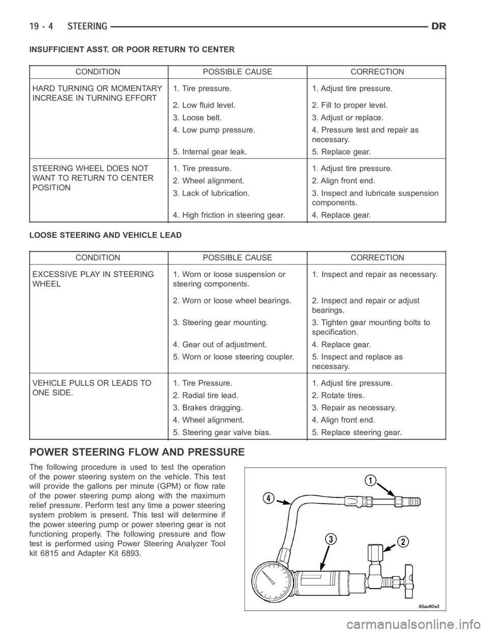
The following procedure is used to test the operation
of the power steering system on the vehicle. This test
will provide the gallons per minute (GPM) or flow rate
of the power steering pump along with the maximum
relief pressure. Perform test any time a power steering
system problem is present. This test will determine if
the power steering pump or power steering gear is not
functioning properly. The following pressure and flow
test is performed using Power Steering Analyzer Tool
kit 6815 and Adapter Kit 6893.
Page 2445 of 5267
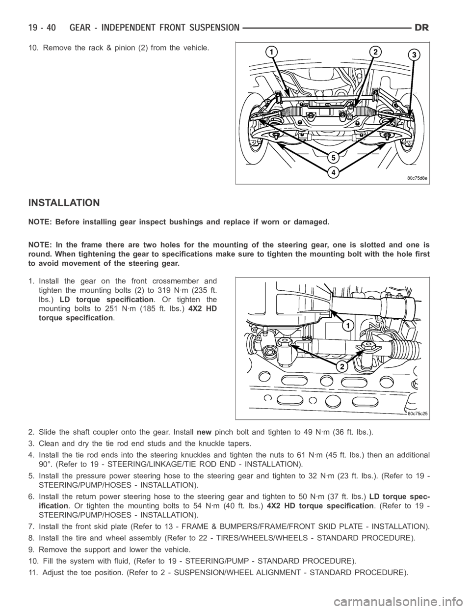
10. Remove the rack & pinion (2) from the vehicle.
INSTALLATION
NOTE: Before installing gear inspect bushings and replace if worn or damaged.
NOTE: In the frame there are two holes for the mounting of the steering gear,oneisslottedandoneis
round. When tightening the gear to specificationsmakesuretotightenthemounting bolt with the hole first
to avoid movement of the steering gear.
1. Install the gear on the front crossmember and
tighten the mounting bolts (2) to 319 Nꞏm (235 ft.
lbs.)LD torque specification.Ortightenthe
mounting bolts to 251 Nꞏm (185 ft. lbs.)4X2 HD
torque specification.
2. Slide the shaft coupler onto the gear. Installnewpinch bolt and tighten to 49 Nꞏm (36 ft. lbs.).
3. Clean and dry the tie rod end studs and the knuckle tapers.
4. Install the tie rod ends into the steering knuckles and tighten the nuts to61Nꞏm(45ft.lbs.)thenanadditional
90°. (Refer to 19 - STEERING/LINKAGE/TIE ROD END - INSTALLATION).
5. Install the pressure power steering hose to the steering gear and tightento32Nꞏm(23ft.lbs.).(Referto19-
STEERING/PUMP/HOSES - INSTALLATION).
6. Install the return power steering hose to the steering gear and tighten to50Nꞏm(37ft.lbs.)LD torque spec-
ification. Or tighten the mounting bolts to 54 Nꞏm (40 ft. lbs.)4X2 HD torque specification.(Referto19-
STEERING/PUMP/HOSES - INSTALLATION).
7. Install the front skid plate (Refer to 13 - FRAME & BUMPERS/FRAME/FRONT SKID PLATE - INSTALLATION).
8. Install the tire and wheel assembly (Refer to 22 - TIRES/WHEELS/WHEELS -STANDARD PROCEDURE).
9. Remove the support and lower the vehicle.
10. Fill the system with fluid, (Refer to 19 - STEERING/PUMP - STANDARD PROCEDURE).
11. Adjust the toe position. (Refer to 2 - SUSPENSION/WHEEL ALIGNMENT - STANDARD PROCEDURE).
Page 2914 of 5267
The 42RLE is a four-speed transmission that is a conventional hydraulic/mechanical assembly controlled with adap-
tive electronic controls and monitors. The hydraulic system of the transmission consists of the transmission fluid,
fluid passages, hydraulic valves, and various line pressure control components. An input clutch assembly which
houses the underdrive, overdrive, and reverse clutches is used. It also utilizes separate holding clutches: 2nd/4th
gear and Low/Reverse. The primary mechanical components of the transmission consist of the following:
Three multiple disc input clutches
Two multiple disc holding clutches
Four hydraulic accumulators
Two planetary gear sets
Hydraulic oil pump
Valve body
Solenoid/Pressure switch assembly
Control of the transmission is accomplished by fully adaptive electronics. Optimum shift scheduling is accomplished
through continuous real-time sensor feedback information provided to the Transmission Control Module (TCM) por-
tion of the Powertrain Control Module (PCM).
The TCM is the heart of the electronic control system and relies on information from various direct and indirect
inputs (sensors, switches, etc.) to determine driver demand and vehicle operating conditions. With this information,
the TCM can calculate and perform timely and quality shifts through various output or control devices (solenoid
pack, transmission control relay, etc.).
The TCM also performs certain self-diagnostic functions and provides comprehensive information (sensor data,
DTC’s, etc.) which is helpful in proper diagnosis and repair. This informationcanbeviewedwiththescantool.
TRANSMISSION IDENTIFICATION
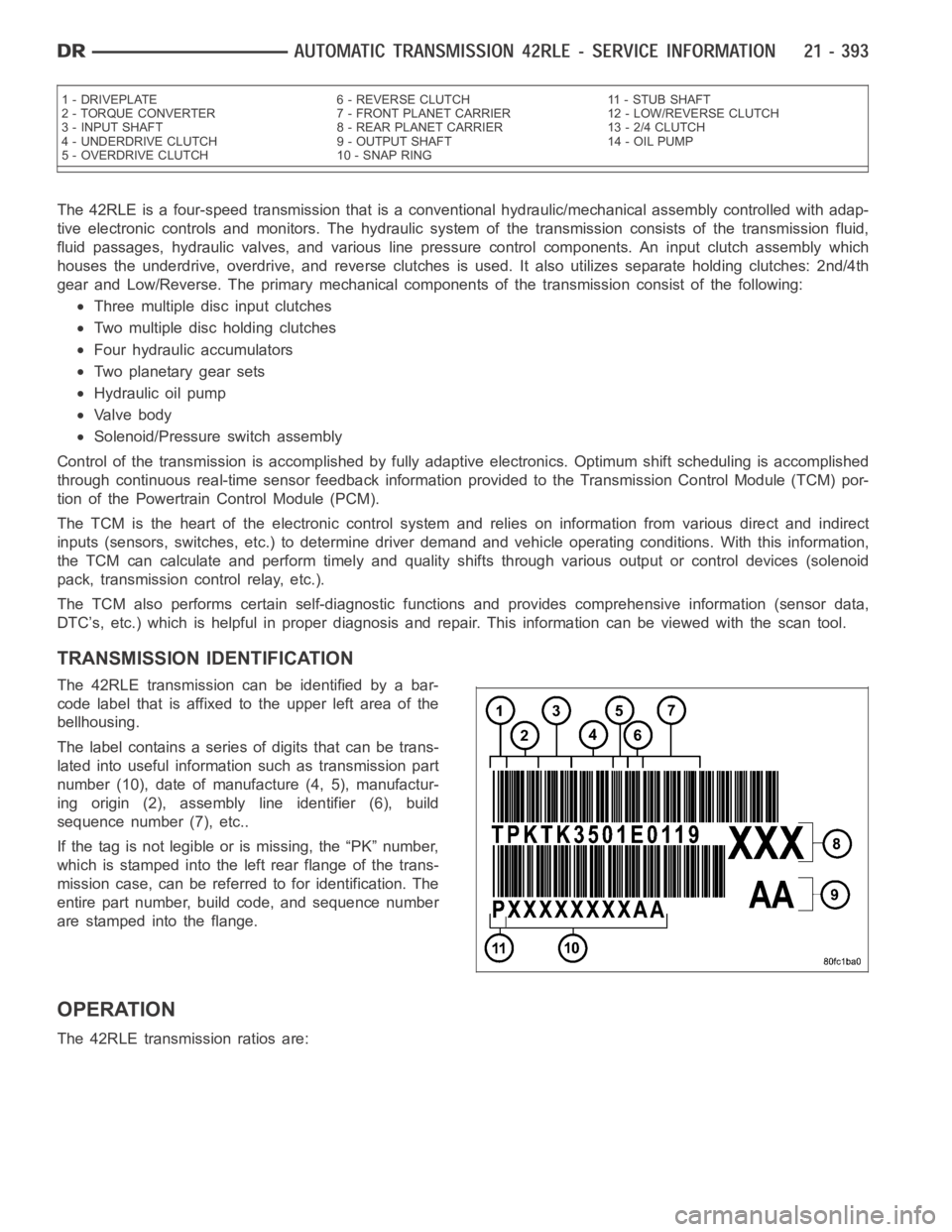
The 42RLE transmission can be identified by a bar-
code label that is affixed to the upper left area of the
bellhousing.
The label contains a series of digits that can be trans-
lated into useful information such as transmission part
number (10), date of manufacture (4, 5), manufactur-
ing origin (2), assembly line identifier (6), build
sequence number (7), etc..
If the tag is not legible or is missing, the “PK” number,
which is stamped into the left rear flange of the trans-
mission case, can be referred to for identification. The
entire part number, build code, and sequence number
are stamped into the flange.
OPERATION
The 42RLE transmission ratios are:
1 - DRIVEPLATE 6 - REVERSE CLUTCH 11 - STUB SHAFT
2 - TORQUE CONVERTER 7 - FRONT PLANET CARRIER 12 - LOW/REVERSE CLUTCH
3 - INPUT SHAFT 8 - REAR PLANET CARRIER 13 - 2/4 CLUTCH
4 - UNDERDRIVE CLUTCH 9 - OUTPUT SHAFT 14 - OIL PUMP
5 - OVERDRIVE CLUTCH 10 - SNAP RING
Page 3940 of 5267
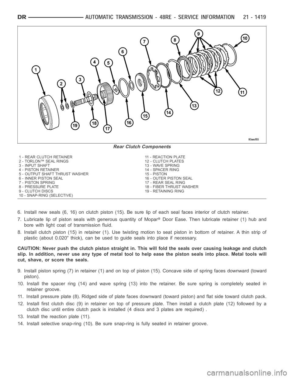
6. Install new seals (6, 16) on clutch piston (15). Be sure lip of each seal faces interior of clutch retainer.
7. Lubricate lip of piston seals with generous quantity of Mopar
Door Ease. Then lubricate retainer (1) hub and
bore with light coat of transmission fluid.
8. Install clutch piston (15) in retainer (1). Use twisting motion to seat piston in bottom of retainer. A thin strip of
plastic (about 0.020
thick), can be used to guide seals into place if necessary.
CAUTION: Never push the clutch piston straight in. This will fold the sealsover causing leakage and clutch
slip. In addition, never use any type of metal tool to help ease the piston seals into place. Metal tools will
cut, shave, or score the seals.
9. Install piston spring (7) in retainer (1) and on top of piston (15). Concave side of spring faces downward (toward
piston).
10. Install the spacer ring (14) and wave spring (13) into the retainer. Be sure spring is completely seated in
retainer groove.
11. Install pressure plate (8). Ridged side of plate faces downward (toward piston) and flat side toward clutch pack.
12. Install first clutch disc (9) in retainer on top of pressure plate. Theninstall a clutch plate (12) followed by a
clutch disc until entire clutch pack is installed (4 discs and 3 plates are required) .
13. Install the reaction plate (11).
14. Install selective snap-ring (10). Be sure snap-ring is fully seated inretainer groove.
Rear Clutch Components
1 - REAR CLUTCH RETAINER 11 - REACTION PLATE
2 - TORLON™ SEAL RINGS 12 - CLUTCH PLATES
3 - INPUT SHAFT 13 - WAVE SPRING
4 - PISTON RETAINER 14 - SPACER RING
5 - OUTPUT SHAFT THRUST WASHER 15 - PISTON
6 - INNER PISTON SEAL 16 - OUTER PISTON SEAL
7 - PISTON SPRING 17 - REAR SEAL RING
8 - PRESSURE PLATE 18 - FIBER THRUST WASHER
9 - CLUTCH DISCS 19 - RETAINING RING
10 - SNAP-RING (SELECTIVE)
Page 4223 of 5267
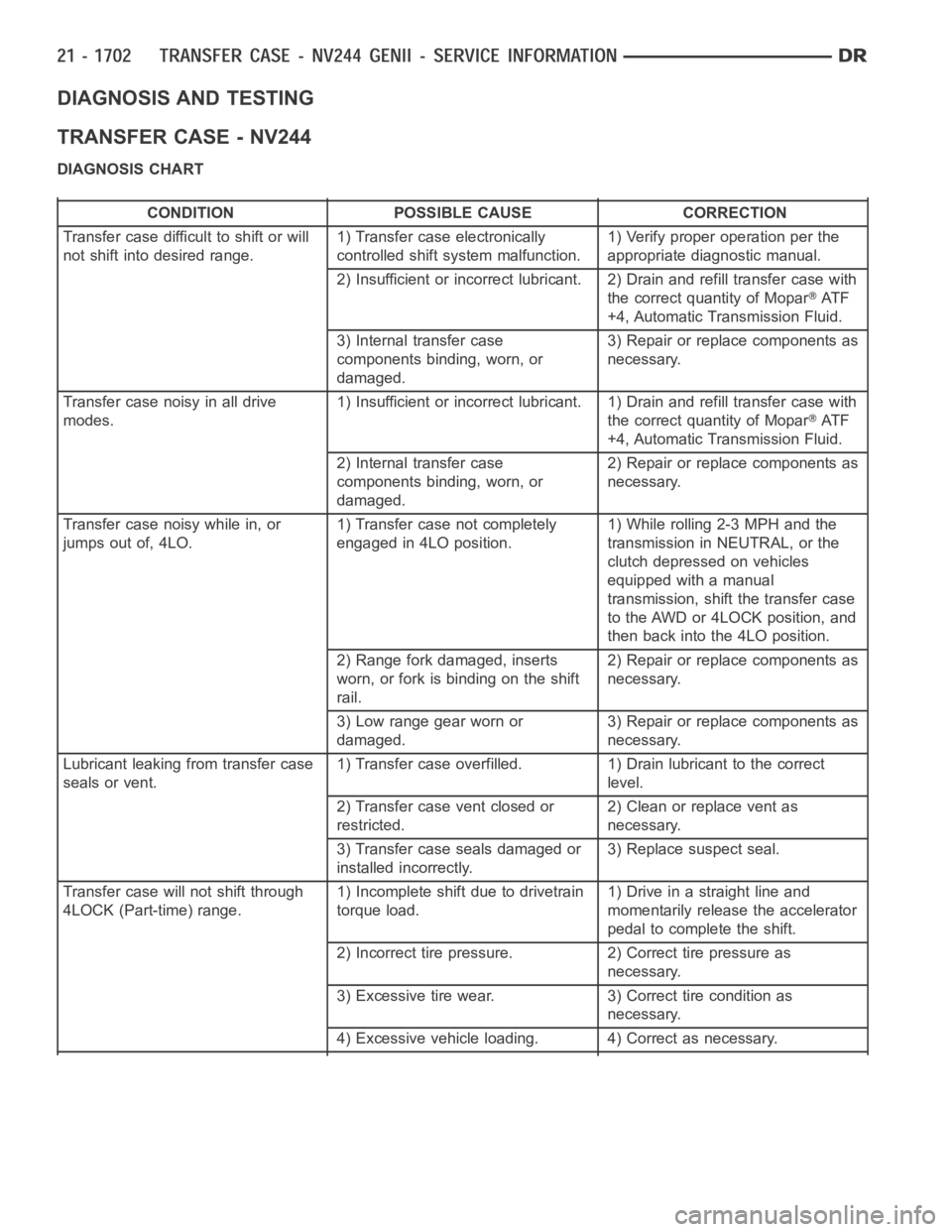
DIAGNOSIS AND TESTING
TRANSFER CASE - NV244
DIAGNOSIS CHART
CONDITION POSSIBLE CAUSE CORRECTION
Transfer case difficult to shift or will
not shift into desired range.1) Transfer case electronically
controlled shift system malfunction.1) Verify proper operation per the
appropriate diagnostic manual.
2) Insufficient or incorrect lubricant. 2) Drain and refill transfer casewith
the correct quantity of Mopar
AT F
+4, Automatic Transmission Fluid.
3) Internal transfer case
components binding, worn, or
damaged.3) Repair or replace components as
necessary.
Transfer case noisy in all drive
modes.1) Insufficient or incorrect lubricant. 1) Drain and refill transfer casewith
the correct quantity of Mopar
AT F
+4, Automatic Transmission Fluid.
2) Internal transfer case
components binding, worn, or
damaged.2) Repair or replace components as
necessary.
Transfer case noisy while in, or
jumps out of, 4LO.1) Transfer case not completely
engaged in 4LO position.1) While rolling 2-3 MPH and the
transmission in NEUTRAL, or the
clutch depressed on vehicles
equipped with a manual
transmission, shift the transfer case
to the AWD or 4LOCK position, and
then back into the 4LO position.
2) Range fork damaged, inserts
worn, or fork is binding on the shift
rail.2) Repair or replace components as
necessary.
3) Low range gear worn or
damaged.3) Repair or replace components as
necessary.
Lubricant leaking from transfer case
seals or vent.1) Transfer case overfilled. 1) Drain lubricant to the correct
level.
2) Transfer case vent closed or
restricted.2) Clean or replace vent as
necessary.
3) Transfer case seals damaged or
installed incorrectly.3) Replace suspect seal.
Transfer case will not shift through
4LOCK (Part-time) range.1) Incomplete shift due to drivetrain
torque load.1)Driveinastraightlineand
momentarily release the accelerator
pedal to complete the shift.
2) Incorrect tire pressure. 2) Correct tire pressure as
necessary.
3) Excessive tire wear. 3) Correct tire condition as
necessary.
4) Excessive vehicle loading. 4) Correct as necessary.
Page 4314 of 5267
TIRES/WHEELS
TABLE OF CONTENTS
page page
TIRES/WHEELS
DIAGNOSIS AND TESTING
TIRE AND WHEEL RUNOUT .................. 2
STANDARD PROCEDURE
MATCH MOUNTING .......................... 4
TIRE AND WHEEL BALANCE ................. 5
TIRE ROTATION ............................. 6
SPECIFICATIONS
TORQUE .................................... 7
TIRES
DESCRIPTION
TIRES ....................................... 8
SPARE / TEMPORARY TIRE .................. 8
RADIAL – PLY TIRES ......................... 8
TIRE PRESSURE FOR HIGH SPEEDS......... 9
REPLACEMENT TIRES ....................... 9
TIRE INFLATION PRESSURES ................ 9
DIAGNOSIS AND TESTING
PRESSURE GAUGES ....................... 10
TIRE NOISE OR VIBRATION ................. 10
TREAD WEAR INDICATORS ................. 10
TIRE WEAR PATTERNS ..................... 11
TIRE/VEHICLE LEAD ........................ 12
STANDARD PROCEDURE
TIRE REPAIR AREA ......................... 13
CLEANING
TIRES ..................................... 13SPECIFICATIONS
TIRE REVOLUTIONS PER MILE .............. 13
WHEELS
DESCRIPTION
DESCRIPTION .............................. 15
WHEEL DESIGN ............................ 16
DIAGNOSIS AND TESTING
WHEEL INSPECTION....................... 16
STANDARD PROCEDURE
WHEEL REPLACEMENT ..................... 16
DUAL REAR WHEEL INSTALLATION .......... 18
STUDS
REMOVAL .................................... 20
INSTALLATION ............................... 20
WHEEL COVER
REMOVAL .................................... 22
INSTALLATION
REAR ...................................... 22
FRONT .................................... 22
SPARE TIRE
DESCRIPTION
SPARE / TEMPORARY TIRE ................. 23
FULL SIZE, SPARE WHEEL WITH
MATCHING TIRE............................ 23
Page 4322 of 5267
Radial-ply tires have the same load-carrying capacity as other types of tires of the same size. They also use the
same recommended inflation pressures.
The use of oversized tires, either in the front or rear of the vehicle, can cause vehicle drive train failure. This could
also cause inaccurate wheel speed signals when the vehicle is equipped with Anti-Lock Brakes.
The use of tires from different manufactures on the same vehicle is NOT recommended. The proper tire pressure
should be maintained on all four tires.
TIRE PRESSURE FOR HIGH SPEEDS
For proper tire pressure specification refer to the Owners Manual.
REPLACEMENT TIRES
The original equipment tires provide a proper balance of many characteristics such as:
Ride
Noise
Handling
Durability
Tread life
Traction
Rolling resistance
Speed capability
It is recommended that tires equivalent to the original equipment tires beused when replacement is needed.
Failure to use equivalent replacement tires may adversely affect the safety and handling of the vehicle.
The use of oversize tires may cause interference with vehicle components.Under extremes of suspension and
steering travel, interference with vehicle components may cause tire damage.
WARNING: Failure to equip the vehicle with tires having adequate speed capability can result in sudden tire
failure.
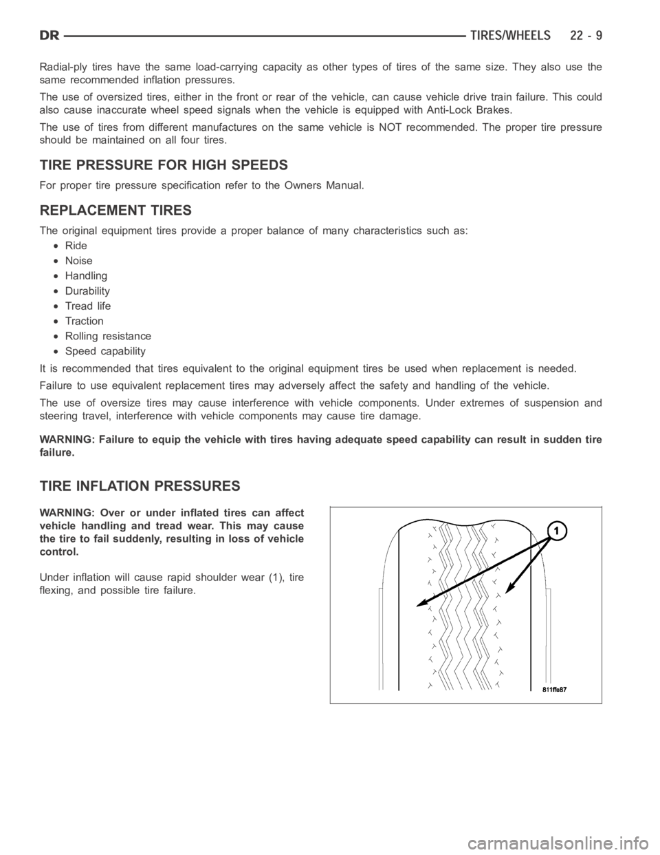
TIRE INFLATION PRESSURES
WARNING: Over or under inflated tires can affect
vehicle handling and tread wear. This may cause
the tire to fail suddenly, resulting in loss of vehicle
control.
Under inflation will cause rapid shoulder wear (1), tire
flexing, and possible tire failure.