Page 4687 of 5267

RELAY PACK
DESCRIPTION
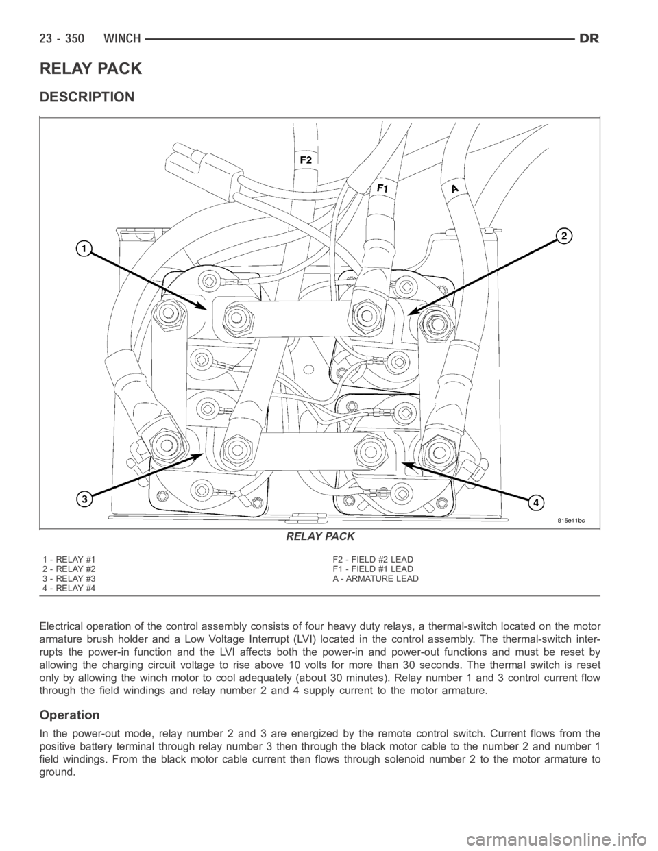
Electrical operation of the control assembly consists of four heavy duty relays, a thermal-switch located on the motor
armature brush holder and a Low Voltage Interrupt (LVI) located in the control assembly. The thermal-switch inter-
rupts the power-in function and the LVI affects both the power-in and power-out functions and must be reset by
allowing the charging circuit voltage to rise above 10 volts for more than 30 seconds. The thermal switch is reset
only by allowing the winch motor to cool adequately (about 30 minutes). Relay number 1 and 3 control current flow
through the field windings and relay number 2 and 4 supply current to the motor armature.
Operation
In the power-out mode, relay number 2 and 3 are energized by the remote control switch. Current flows from the
positive battery terminal through relay number 3 then through the black motor cable to the number 2 and number 1
field windings. From the black motor cable current then flows through solenoid number 2 to the motor armature to
ground.
RELAY PACK
1-RELAY#1
2-RELAY#2
3-RELAY#3
4-RELAY#4F2 - FIELD #2 LEAD
F1 - FIELD #1 LEAD
A - ARMATURE LEAD
Page 4688 of 5267
In power-in mode, relay number 1 and 4 are energized. Current again flows from the battery positive cable, but this
time current flows through solenoid number 1 then through field winding number 1. Current flowing in the reverse
direction through the field windings cause the motor to turn in the opposite direction. From the red motor cable
current then flows through relay number 4 to the black cable going to the motor armature to ground.
REMOVAL
1. Disconnect and isolate battery negative cable (3).
2. Remove the winch assembly (2). (Refer to 23 -
BODY/WINCH - REMOVAL)
Page 4689 of 5267
3. Remove the nut and disconnect the red battery
positive cable (1).
NOTE: Relay #4 shown, all others similar.
4. Remove the control wire nuts (1) and disconnect
the control wires (2) from each relay.
Page 4690 of 5267
INSTALLATION
NOTE: Relay #4 shown, all others similar.
1. Install the control wires (2) to all the relays and
install the nuts (1).
2. Tighten the nuts to 3 Nꞏm (25 in. lbs.).
3. Install the red battery positive cable (1) and install
the switch wire.
4. Install the nut and tighten to 10 Nꞏm (85 in. lbs.).
Page 4691 of 5267
5. Install the relay pack cover (1) and install the three
screws (2).
6. Install the winch assembly (2). (Refer to 23 -
BODY/WINCH - INSTALLATION)
7. Connect the battery negative cable (3) and verify
winch operation.
Page 5193 of 5267

EMISSIONS CONTROL
DESCRIPTION
STATE DISPLAY TEST MODE
The switch inputs to the Powertrain Control Module (PCM) have two recognized states; HIGH and LOW. For this
reason, the PCM cannot recognize the difference between a selected switchposition versus an open circuit, a short
circuit, or a defective switch. If the State Display screen shows the changefromHIGHtoLOWorLOWtoHIGH,
assume the entire switch circuit to the PCM functions properly. Connect the DRB scan tool to the data link con-
nector and access the state display screen. Then access either State Display Inputs and Outputs or State Display
Sensors.
CIRCUIT ACTUATION TEST MODE
The Circuit Actuation Test Mode checks for proper operation of output circuits or devices the Powertrain Control
Module (PCM) may not internally recognize. The PCM attempts to activate these outputs and allow an observer to
verify proper operation. Most of the tests provide an audible or visual indication of device operation (click of relay
contacts, fuel spray, etc.). Except for intermittent conditions, if a device functions properly during testing, assume the
device, its associated wiring, and driver circuit work correctly. Connect the DRB scan tool to the data link connector
and access the Actuators screen.
DIAGNOSTIC TROUBLE CODES
A Diagnostic Trouble Code (DTC) indicates the PCM has recognized an abnormal condition in the system.
Remember that DTC’s are the results of a system or circuit failure, but do not directly identify the failed
component or components.
BULB CHECK
Each time the ignition key is turned to the ON position, the malfunction indicator (check engine) lamp on the instru-
ment panel should illuminate for approximately 2 seconds then go out. Thisis done for a bulb check.
OBTAINING DTC’S USING DRB SCAN TOOL
1. Obtain the applicable Powertrain Diagnostic Manual.
2. Obtain the DRB Scan Tool.
3. Connect the DRB Scan Tool to the data link (diagnostic) connector. This connector is located in the passenger
compartment at the lower edge of instrument panel, and near the steering column.
4. Turn the ignition switch on and access the “Read Fault” screen.
5. Record all the DTC’s and “freeze frame” information shown on the DRB scantool.
6. To erase DTC’s, use the “Erase Trouble Code” data screen on the DRB scan tool.Do not erase any DTC’s
until problems have been investigated and repairs have been performed.
TA S K M A N A G E R
The PCM is responsible for efficiently coordinating the operation of all the emissions-related components. The PCM
is also responsible for determining if the diagnostic systems are operating properly. The software designed to carry
out these responsibilities is called the ’Task Manager’.
MONITORED SYSTEMS
There are new electronic circuit monitors that check fuel, emission, engine and ignition performance. These moni-
tors use information from various sensor circuits to indicate the overalloperation of the fuel, engine, ignition and
emission systems and thus the emissions performance of the vehicle.
The fuel, engine, ignition and emission systems monitors do not indicate aspecific component problem. They do
indicate that there is an implied problem within one of the systems and thata specific problem must be diagnosed.
If any of these monitors detect a problem affecting vehicle emissions, theMalfunction Indicator Lamp (MIL) will be
illuminated. These monitors generate Diagnostic Trouble Codes that can be displayed with the MIL or a scan tool.