Page 4671 of 5267
3. Position the relay pack onto the motor and tighten
thebandclamps(2).
4. Connect the thermal switch electrical connector.
Page 4677 of 5267

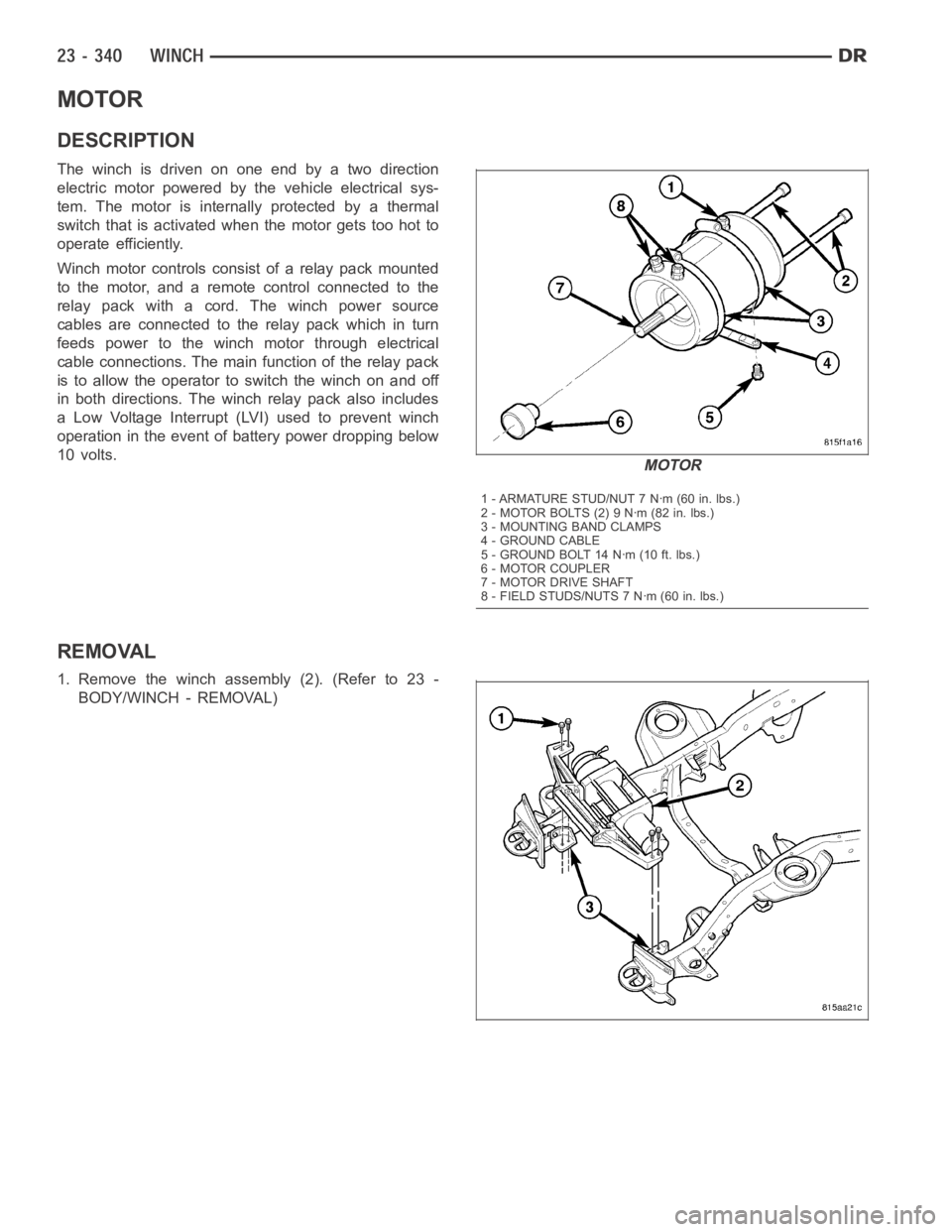
MOTOR
DESCRIPTION
The winch is driven on one end by a two direction
electric motor powered by the vehicle electrical sys-
tem. The motor is internally protected by a thermal
switch that is activated when the motor gets too hot to
operate efficiently.
Winch motor controls consist of a relay pack mounted
to the motor, and a remote control connected to the
relay pack with a cord. The winch power source
cables are connected to the relay pack which in turn
feeds power to the winch motor through electrical
cable connections. The main function of the relay pack
is to allow the operator to switch the winch on and off
in both directions. The winch relay pack also includes
a Low Voltage Interrupt (LVI) used to prevent winch
operation in the event of battery power dropping below
10 volts.
REMOVAL
1. Remove the winch assembly (2). (Refer to 23 -
BODY/WINCH - REMOVAL)
MOTOR
1 - ARMATURE STUD/NUT 7 Nꞏm (60 in. lbs.)
2-MOTORBOLTS(2)9Nꞏm(82in.lbs.)
3 - MOUNTING BAND CLAMPS
4 - GROUND CABLE
5 - GROUND BOLT 14 Nꞏm (10 ft. lbs.)
6 - MOTOR COUPLER
7 - MOTOR DRIVE SHAFT
8 - FIELD STUDS/NUTS 7 Nꞏm (60 in. lbs.)
Page 4678 of 5267
2. Separate one of the roller shaft clips (1), remove
the shaft (3) and the roller (4).
3. Remove the bolts (3) and separate the support
bracket (1) from the winch assembly (2).
4. Remove the relay pack (1). (Refer to 23 - BODY/
WINCH/RELAY PACK - REMOVAL)
Page 4680 of 5267
2. Position the motor drive shaft into the motor cou-
pler splines and install the motor (2).
3. Install the bolts (1) and tighten to 9 Nꞏm (82 in.
lbs.).
4. Install the relay pack (1). (Refer to 23 - BODY/
WINCH/RELAY PACK - INSTALLATION)
Page 4683 of 5267
RELAY
REMOVAL
1. Remove the relay pack (1). (Refer to 23 - BODY/
WINCH/RELAY PACK - REMOVAL)
2. Remove the nuts (2 & 3), disconnect the cables
and remove the bus straps (4).
Page 4684 of 5267
NOTE: Relay #4 shown, all others similar.
3. Remove the nuts (1) and disconnect the control
wires (2).
4. Slide the relay (1) out of the retaining tab (2) and
remove.
Page 4685 of 5267
INSTALLATION
NOTE: Relay #4 shown, all others similar.
1. Slide the relay (1) into the retaining tab (2).
2. Install the control wires (2) and install the nuts (1).
3. Tighten the nuts to 3 Nꞏm (25 in. lbs.).
Page 4686 of 5267
4. Install the bus straps (4) and connect the cables.
5. Install the nuts (2 & 3) and tighten to 9.5 Nꞏm (85
in. lbs.).
6. Install the relay pack (1). (Refer to 23 - BODY/
WINCH/RELAY PACK - INSTALLATION)