2006 DODGE RAM SRT-10 relay
[x] Cancel search: relayPage 3754 of 5267
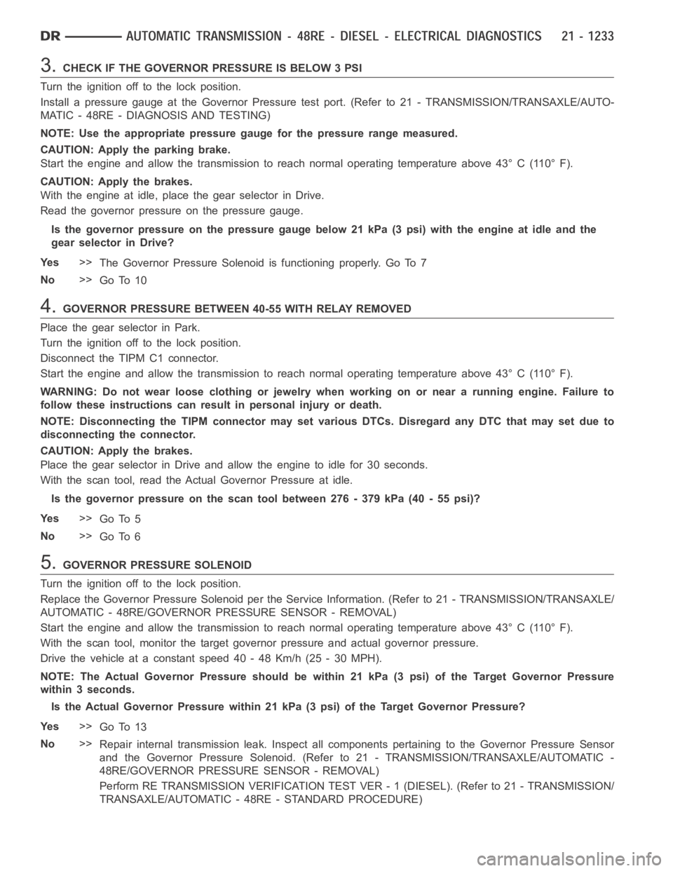
3.CHECK IF THE GOVERNOR PRESSURE IS BELOW 3 PSI
Turn the ignition off to the lock position.
Install a pressure gauge at the Governor Pressure test port. (Refer to 21 - TRANSMISSION/TRANSAXLE/AUTO-
MATIC - 48RE - DIAGNOSIS AND TESTING)
NOTE: Use the appropriate pressure gauge for the pressure range measured.
CAUTION: Apply the parking brake.
Start the engine and allow the transmission to reach normal operating temperature above 43° C (110° F).
CAUTION: Apply the brakes.
With the engine at idle, place the gear selector in Drive.
Read the governor pressure on the pressure gauge.
Is the governor pressure on the pressure gauge below 21 kPa (3 psi) with the engine at idle and the
gear selector in Drive?
Ye s>>
The Governor Pressure Solenoid is functioning properly. Go To 7
No>>
Go To 10
4.GOVERNOR PRESSURE BETWEEN 40-55 WITH RELAY REMOVED
Place the gear selector in Park.
Turn the ignition off to the lock position.
Disconnect the TIPM C1 connector.
Start the engine and allow the transmission to reach normal operating temperature above 43° C (110° F).
WARNING: Do not wear loose clothing or jewelry when working on or near a running engine. Failure to
follow these instructions can result in personal injury or death.
NOTE: Disconnecting the TIPM connector may set various DTCs. Disregard anyDTCthatmaysetdueto
disconnecting the connector.
CAUTION: Apply the brakes.
Place the gear selector in Drive and allow the engine to idle for 30 seconds.
With the scan tool, read the Actual Governor Pressure at idle.
Is the governor pressure on the scan tool between 276 - 379 kPa (40 - 55 psi)?
Ye s>>
Go To 5
No>>
Go To 6
5.GOVERNOR PRESSURE SOLENOID
Turn the ignition off to the lock position.
Replace the Governor Pressure Solenoid per the Service Information. (Refer to 21 - TRANSMISSION/TRANSAXLE/
AUTOMATIC - 48RE/GOVERNOR PRESSURE SENSOR - REMOVAL)
Start the engine and allow the transmission to reach normal operating temperature above 43° C (110° F).
With the scan tool, monitor the target governor pressure and actual governor pressure.
Drivethevehicleataconstantspeed40-48Km/h(25-30MPH).
NOTE: The Actual Governor Pressure should be within 21 kPa (3 psi) of the Target Governor Pressure
within 3 seconds.
Is the Actual Governor Pressure within 21 kPa (3 psi) of the Target GovernorPressure?
Ye s>>
Go To 13
No>>
Repair internal transmission leak. Inspect all components pertaining tothe Governor Pressure Sensor
and the Governor Pressure Solenoid. (Refer to 21 - TRANSMISSION/TRANSAXLE/AUTOMATIC -
48RE/GOVERNOR PRESSURE SENSOR - REMOVAL)
Perform RE TRANSMISSION VERIFICATION TEST VER - 1 (DIESEL). (Refer to 21 - TRANSMISSION/
TRANSAXLE/AUTOMATIC - 48RE - STANDARD PROCEDURE)
Page 3755 of 5267
6.CHECK GAUGE PRESSURE 40-55 WITH RELAY OUT
Place the gear selector in Park.
Turn the ignition off to the lock position.
Disconnect the TIPM C1 connector.
Start the engine and allow the transmission to reach normal operating temperature above 43° C (110° F).
WARNING: Do not wear loose clothing or jewelry when working on or near a running engine. Failure to
follow these instructions can result in personal injury or death.
NOTE: Disconnecting the TIPM connector may set various DTCs. Disregard anyDTCthatmaysetdueto
disconnecting the connector.
CAUTION: Apply the brakes.
Place the gear selector in Drive with the engine at idle.
Read the governor pressure on the pressure gauge.
Is the governor pressure on the pressure gauge read between 276 - 379 kPa (40-55psi)?
Ye s>>
Go To 7
No>>
Go To 10
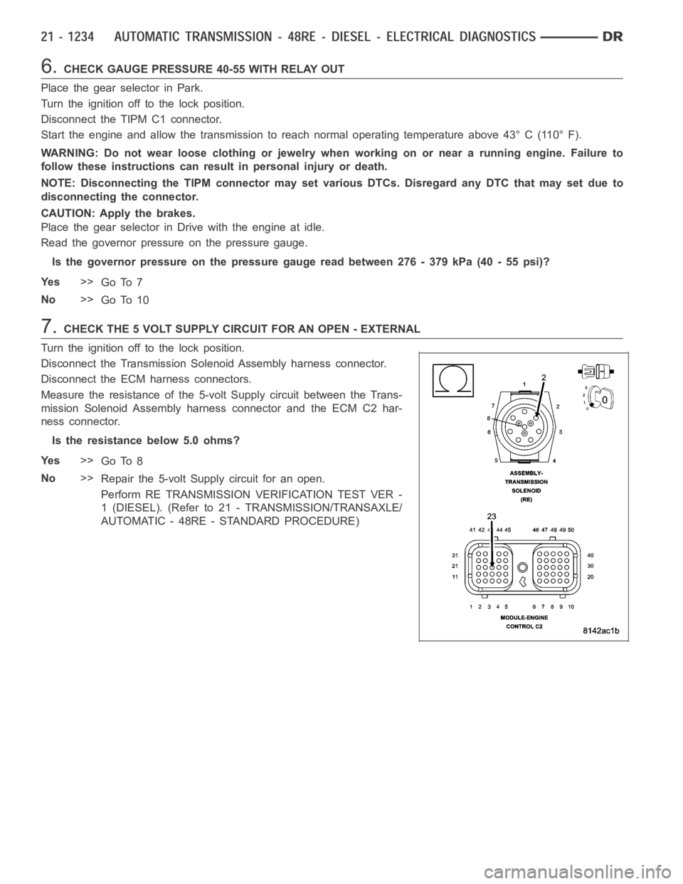
7.CHECK THE 5 VOLT SUPPLY CIRCUIT FOR AN OPEN - EXTERNAL
Turn the ignition off to the lock position.
Disconnect the Transmission Solenoid Assembly harness connector.
Disconnect the ECM harness connectors.
Measure the resistance of the 5-volt Supply circuit between the Trans-
mission Solenoid Assembly harness connector and the ECM C2 har-
ness connector.
Is the resistance below 5.0 ohms?
Ye s>>
Go To 8
No>>
Repair the 5-volt Supply circuit for an open.
Perform RE TRANSMISSION VERIFICATION TEST VER -
1 (DIESEL). (Refer to 21 - TRANSMISSION/TRANSAXLE/
AUTOMATIC - 48RE - STANDARD PROCEDURE)
Page 3772 of 5267
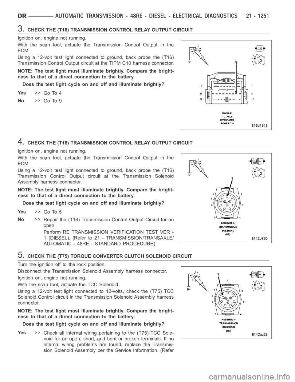
3.CHECK THE (T16) TRANSMISSION CONTROL RELAY OUTPUT CIRCUIT
Ignition on, engine not running.
With the scan tool, actuate the Transmission Control Output in the
ECM.
Using a 12-volt test light connected to ground, back probe the (T16)
Transmission Control Output circuit at the TIPM C10 harness connector.
NOTE: The test light must illuminate brightly. Compare the bright-
ness to that of a direct connection to the battery.
Does the test light cycle on and off and illuminate brightly?
Ye s>>
Go To 4
No>>
Go To 9
4.CHECK THE (T16) TRANSMISSION CONTROL RELAY OUTPUT CIRCUIT
Ignition on, engine not running.
With the scan tool, actuate the Transmission Control Output in the
ECM.
Using a 12-volt test light connected to ground, back probe the (T16)
Transmission Control Output circuit at the Transmission Solenoid
Assembly harness connector.
NOTE: The test light must illuminate brightly. Compare the bright-
ness to that of a direct connection to the battery.
Does the test light cycle on and off and illuminate brightly?
Ye s>>
Go To 5
No>>
Repair the (T16) Transmission Control Output Circuit for an
open.
Perform RE TRANSMISSION VERIFICATION TEST VER -
1 (DIESEL). (Refer to 21 - TRANSMISSION/TRANSAXLE/
AUTOMATIC - 48RE - STANDARD PROCEDURE)
5.CHECK THE (T75) TORQUE CONVERTER CLUTCH SOLENOID CIRCUIT
Turn the ignition off to the lock position.
Disconnect the Transmission Solenoid Assembly harness connector.
Ignition on, engine not running.
With the scan tool, actuate the TCC Solenoid.
Using a 12-volt test light connected to 12-volts, check the (T75) TCC
Solenoid Control circuit in the Transmission Solenoid Assembly harness
connector.
NOTE: The test light must illuminate brightly. Compare the bright-
ness to that of a direct connection to the battery.
Does the test light cycle on and off and illuminate brightly?
Ye s>>
Check all internal wiring pertaining to the (T75) TCC Sole-
noid for an open, short, and bent or broken terminals. If no
internal wiring problems are found, replace the Transmis-
sion Solenoid Assembly per the Service Information. (Refer
Page 3812 of 5267
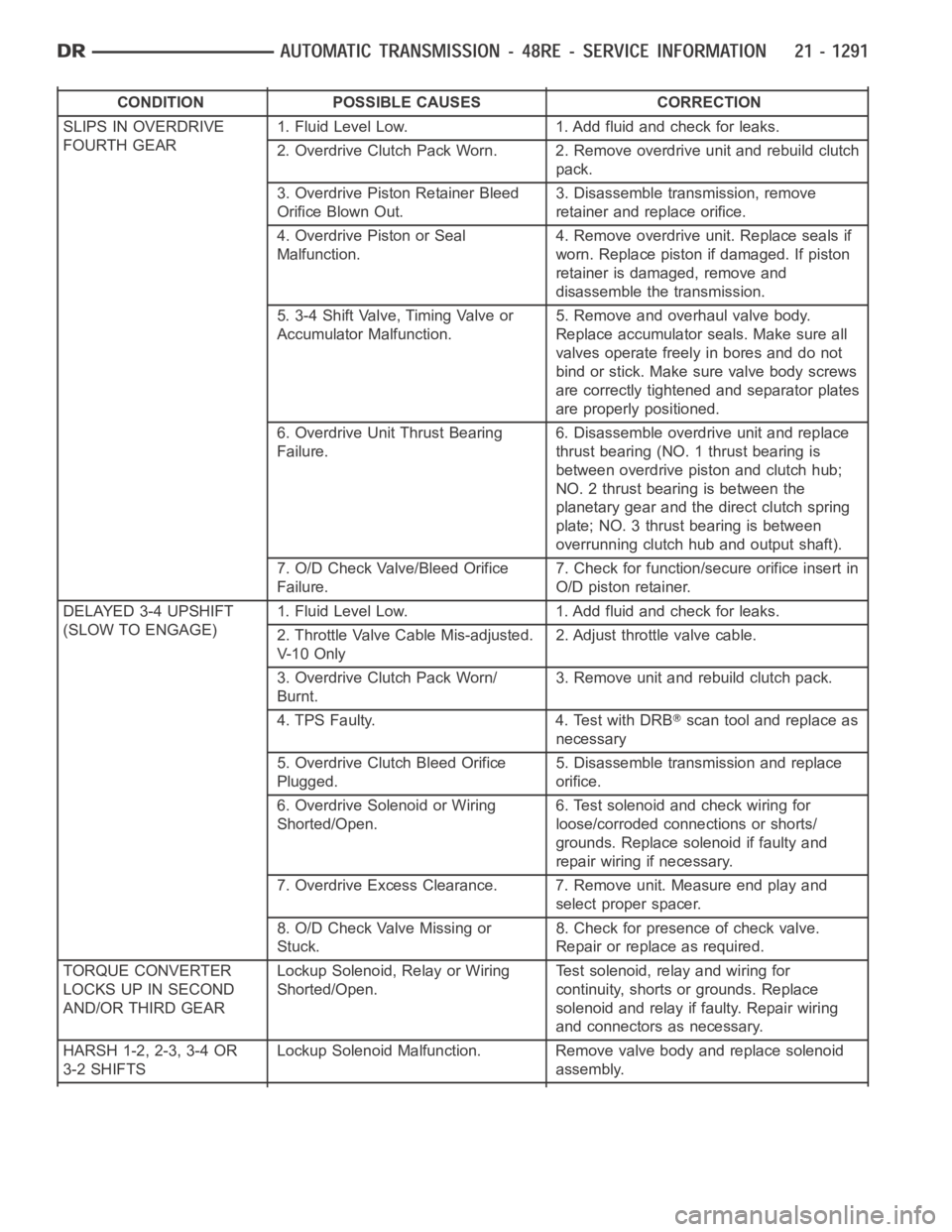
CONDITION POSSIBLE CAUSES CORRECTION
SLIPS IN OVERDRIVE
FOURTH GEAR1. Fluid Level Low. 1. Add fluid and check for leaks.
2. Overdrive Clutch Pack Worn. 2. Remove overdrive unit and rebuild clutch
pack.
3. Overdrive Piston Retainer Bleed
Orifice Blown Out.3. Disassemble transmission, remove
retainer and replace orifice.
4. Overdrive Piston or Seal
Malfunction.4. Remove overdrive unit. Replace seals if
worn. Replace piston if damaged. If piston
retainer is damaged, remove and
disassemble the transmission.
5. 3-4 Shift Valve, Timing Valve or
Accumulator Malfunction.5. Remove and overhaul valve body.
Replace accumulator seals. Make sure all
valves operate freely in bores and do not
bind or stick. Make sure valve body screws
are correctly tightened and separator plates
are properly positioned.
6. Overdrive Unit Thrust Bearing
Failure.6. Disassemble overdrive unit and replace
thrust bearing (NO. 1 thrust bearing is
between overdrive piston and clutch hub;
NO. 2 thrust bearing is between the
planetary gear and the direct clutch spring
plate; NO. 3 thrust bearing is between
overrunning clutch hub and output shaft).
7. O/D Check Valve/Bleed Orifice
Failure.7. Check for function/secure orifice insert in
O/D piston retainer.
DELAYED 3-4 UPSHIFT
(SLOW TO ENGAGE)1. Fluid Level Low. 1. Add fluid and check for leaks.
2. Throttle Valve Cable Mis-adjusted.
V- 1 0 O n l y2. Adjust throttle valve cable.
3. Overdrive Clutch Pack Worn/
Burnt.3. Remove unit and rebuild clutch pack.
4. TPS Faulty. 4. Test with DRB
scan tool and replace as
necessary
5. Overdrive Clutch Bleed Orifice
Plugged.5. Disassemble transmission and replace
orifice.
6. Overdrive Solenoid or Wiring
Shorted/Open.6. Test solenoid and check wiring for
loose/corroded connections or shorts/
grounds. Replace solenoid if faulty and
repair wiring if necessary.
7. Overdrive Excess Clearance. 7. Remove unit. Measure end play and
select proper spacer.
8. O/D Check Valve Missing or
Stuck.8. Check for presence of check valve.
Repair or replace as required.
TORQUE CONVERTER
LOCKS UP IN SECOND
AND/OR THIRD GEARLockup Solenoid, Relay or Wiring
Shorted/Open.Test solenoid, relay and wiring for
continuity, shorts or grounds. Replace
solenoid and relay if faulty. Repair wiring
and connectors as necessary.
HARSH 1-2, 2-3, 3-4 OR
3-2 SHIFTSLockup Solenoid Malfunction. Remove valve body and replace solenoid
assembly.
Page 3869 of 5267
OPERATION
Compensation is required for performance variations of two of the input devices. Though the slope of the transfer
functions is tightly controlled, offset may vary due to various environmental factors or manufacturing tolerances.
The pressure transducer is affected by barometric pressure as well as temperature. Calibration of the zero pressure
offset is required to compensate for shifting output due to these factors.
Normal calibration will be performed when sump temperature is above 50 degrees F, or in the absence of sump
temperature data, after the first 10 minutes of vehicle operation. Calibration of the pressure transducer offset occurs
each time the output shaft speed falls below 200 RPM. Calibration shall be repeated each 3 seconds the output
shaft speed is below 200 RPM. A 0.5 second pulse of 95% duty cycle is applied to the governor pressure solenoid
valve and the transducer output is read during this pulse. Averaging of thetransducer signal isnecessary to reject
electrical noise.
Under cold conditions (below 50 degrees F sump), the governor pressure solenoid valve response may be too slow
to guarantee 0 psi during the 0.5 second calibration pulse. Calibration pulses are continued during this period, how-
ever the transducer output valves are discarded. Transducer offset must be read at key-on, under conditions which
promote a stable reading. This value is retained and becomes the offset during the
coldperiod of operation.
GOVERNOR PRESSURE SOLENOID VALVE
The inlet side of the solenoid valve is exposed to normal transmission linepressure. The outlet side of the valve
leads to the valve body governor circuit.
The solenoid valve regulates line pressure to produce governor pressure.Theaveragecurrentsuppliedtothesole-
noid controls governor pressure. One amp current produces zero kPa/psi governor pressure. Zero amps sets the
maximum governor pressure.
The powertrain control module (PCM) turns on the trans control relay whichsupplies electrical power to the solenoid
valve. Operating voltage is 12 volts (DC). The PCM controls the ground sideof the solenoid using the governor
pressure solenoidcontrol circuit.
GOVERNOR PRESSURE SENSOR
The sensor output signal provides the necessary feedback to the PCM. This feedback is needed to adequately
control governor pressure.
GOVERNOR BODY AND TRANSFER PLATE
The transfer plate channels line pressure to the solenoid valve through the governor body. It also channels governor
pressure from the solenoid valve to the governor circuit. It is the solenoid valve that develops the necessary gov-
ernor pressure.
GOVERNOR PRESSURE CURVES
LOW TRANSMISSION FLUID TEMPERATURE
When the transmission fluid is cold the conventional governor can delay shifts, resulting in higher than normal shift
speeds and harsh shifts. The electronically controlled low temperature governor pressure curve is higher than nor-
mal to make the transmission shift at normal speeds and sooner. The PCM usesa temperature sensor in the trans-
mission oil sump to determine when low temperature governor pressure is needed.
NORMAL OPERATION
Normal operation is refined through the increased computing power of the PCM and through access to data on
engine operating conditions provided by the PCM that were not available with the previous stand-alone electronic
module. This facilitated the development of a load adaptive shift strategy - the ability to alter the shift schedule in
response to vehicle load condition. One manifestation of this capabilityis grade
huntingprevention - the ability of
the transmission logic to delay an upshift on a grade if the engine does not have sufficient power to maintain speed
in the higher gear. The 3-2 downshift and the potential for hunting betweengears occurs with a heavily loaded
vehicle or on steep grades. When hunting occurs, it is very objectionable because shifts are frequent and accom-
panied by large changes in noise and acceleration.
Page 3963 of 5267
SENSOR-TRANSMISSION RANGE
DESCRIPTION
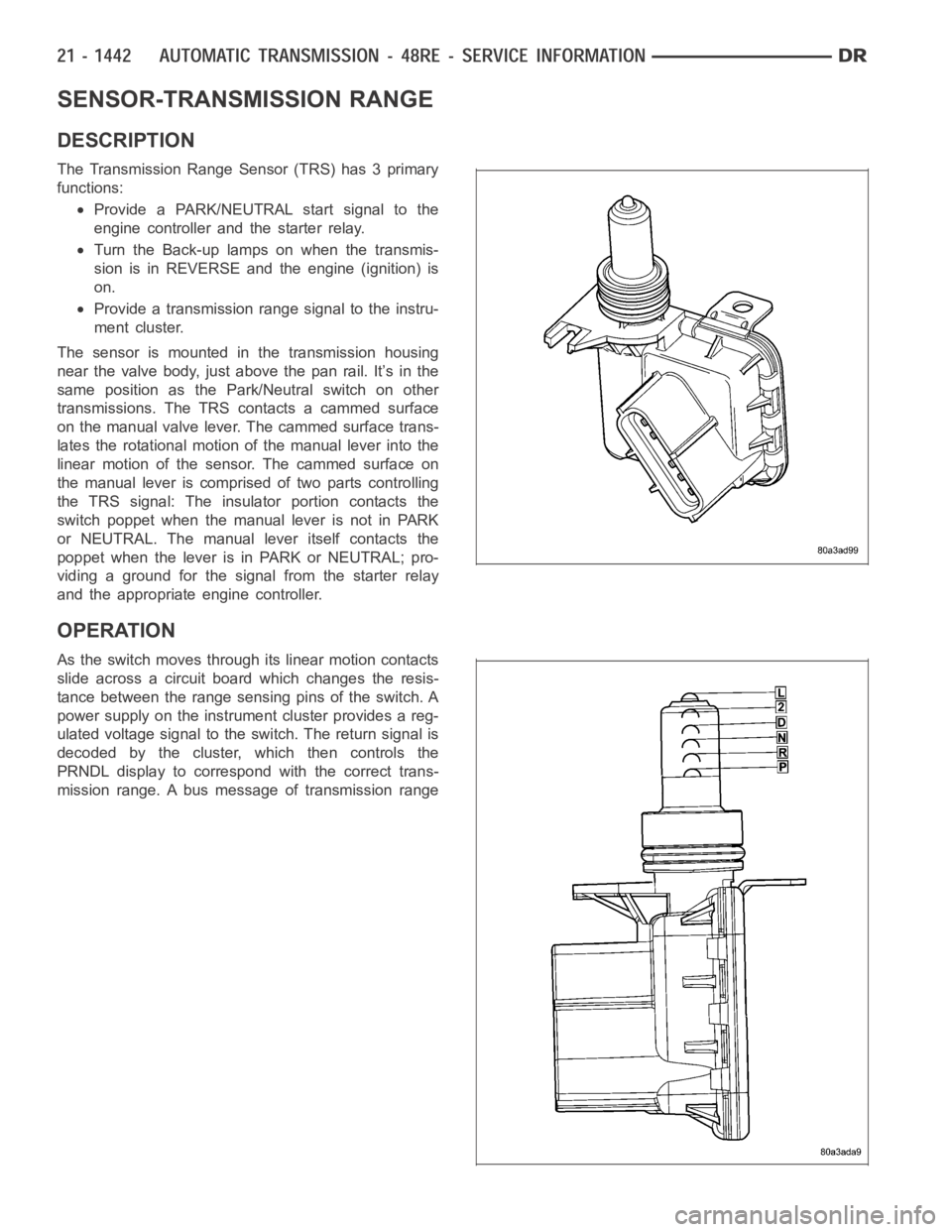
The Transmission Range Sensor (TRS) has 3 primary
functions:
Provide a PARK/NEUTRAL start signal to the
engine controller and the starter relay.
Turn the Back-up lamps on when the transmis-
sion is in REVERSE and the engine (ignition) is
on.
Provide a transmission range signal to the instru-
ment cluster.
The sensor is mounted in the transmission housing
near the valve body, just above the pan rail. It’s in the
same position as the Park/Neutral switch on other
transmissions. The TRS contacts a cammed surface
on the manual valve lever. The cammed surface trans-
lates the rotational motion of the manual lever into the
linear motion of the sensor. The cammed surface on
the manual lever is comprised of two parts controlling
the TRS signal: The insulator portion contacts the
switch poppet when the manual lever is not in PARK
or NEUTRAL. The manual lever itself contacts the
poppet when the lever is in PARK or NEUTRAL; pro-
viding a ground for the signal from the starter relay
and the appropriate engine controller.
OPERATION
As the switch moves through its linear motion contacts
slide across a circuit board which changes the resis-
tance between the range sensing pins of the switch. A
power supply on the instrument cluster provides a reg-
ulated voltage signal to the switch. The return signal is
decoded by the cluster, which then controls the
PRNDL display to correspond with the correct trans-
mission range. A bus message of transmission range
Page 3980 of 5267
1-2 SHIFT CONTROL VALVE
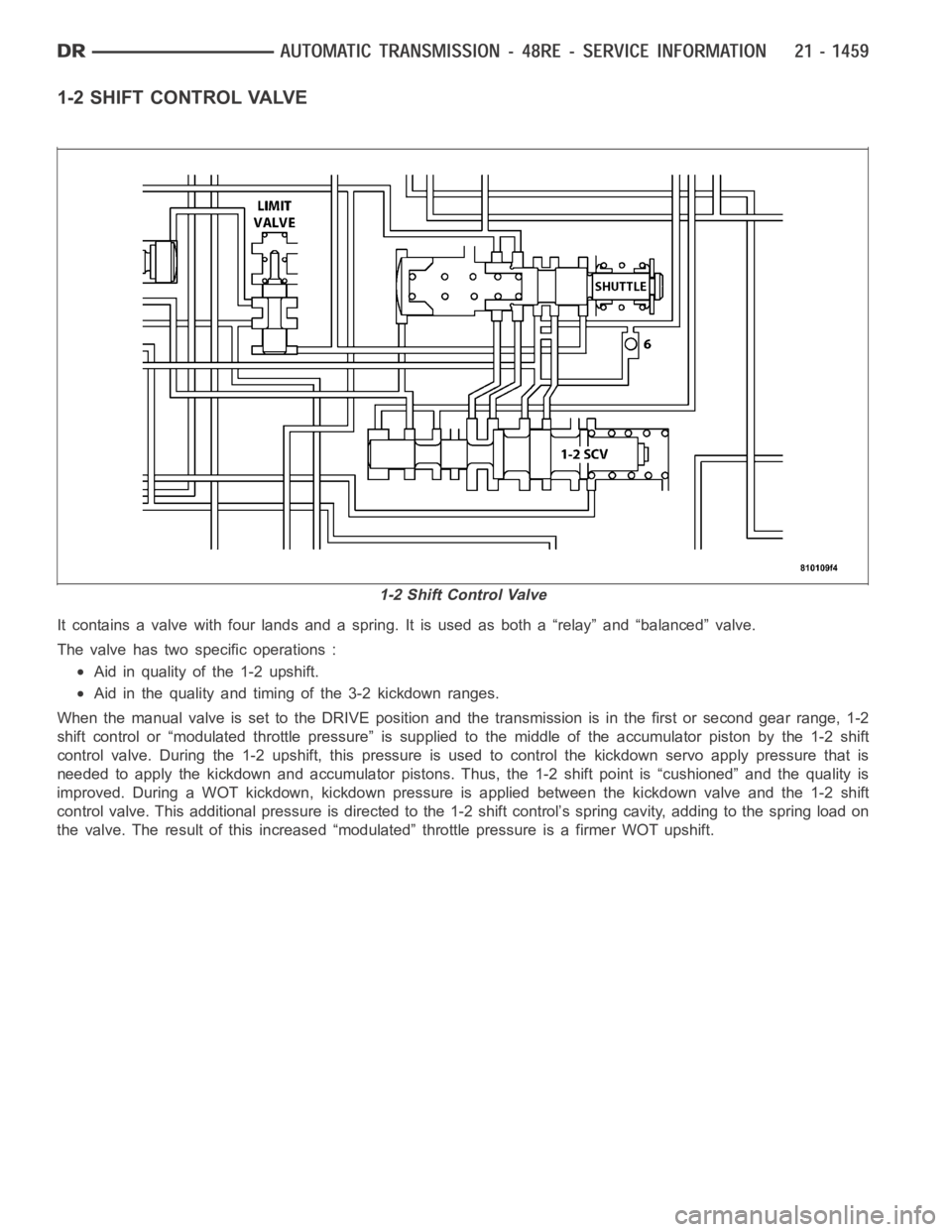
It contains a valve with four lands and a spring. It is used as both a “relay” and “balanced” valve.
The valve has two specific operations :
Aid in quality of the 1-2 upshift.
Aid in the quality and timing of the 3-2 kickdown ranges.
When the manual valve is set to the DRIVE position and the transmission is inthe first or second gear range, 1-2
shift control or “modulated throttle pressure” is supplied to the middle of the accumulator piston by the 1-2 shift
control valve. During the 1-2 upshift, this pressure is used to control thekickdown servo apply pressure that is
needed to apply the kickdown and accumulator pistons. Thus, the 1-2 shift point is “cushioned” and the quality is
improved. During a WOT kickdown, kickdown pressure is applied between thekickdown valve and the 1-2 shift
control valve. This additional pressure is directed to the 1-2 shift control’s spring cavity, adding to the spring load on
the valve. The result of this increased “modulated” throttle pressure is afirmer WOT upshift.
1-2 Shift Control Valve
Page 3990 of 5267

MANUAL VALVE
The manual valve is a relay valve. The purpose of the manual valve is to direct fluid to the correct circuit needed
for a specific gear or driving range. The manual valve, as the name implies,is manually operated by the driver with
a lever located on the side of the valve body. The valve is connected mechanically by either a cable or linkage to
the gearshift mechanism. The valve is held in each of its positions by a spring-loaded roller or ball that engages the
“roostercomb” of the manual valve lever.
Switch Valve - Torque Converter Locked