2006 DODGE RAM SRT-10 ad blue
[x] Cancel search: ad bluePage 1740 of 5267
STANDARD PROCEDURE
STANDARD PROCEDURE - MEASURING TIMING CHAIN WEAR
NOTE: This procedure must be performed with the
timing chain cover removed.
1.Removethetimingchaincover.(Referto9-
ENGINE/VALVE TIMING/TIMING BELT / CHAIN
COVER(S) - REMOVAL).
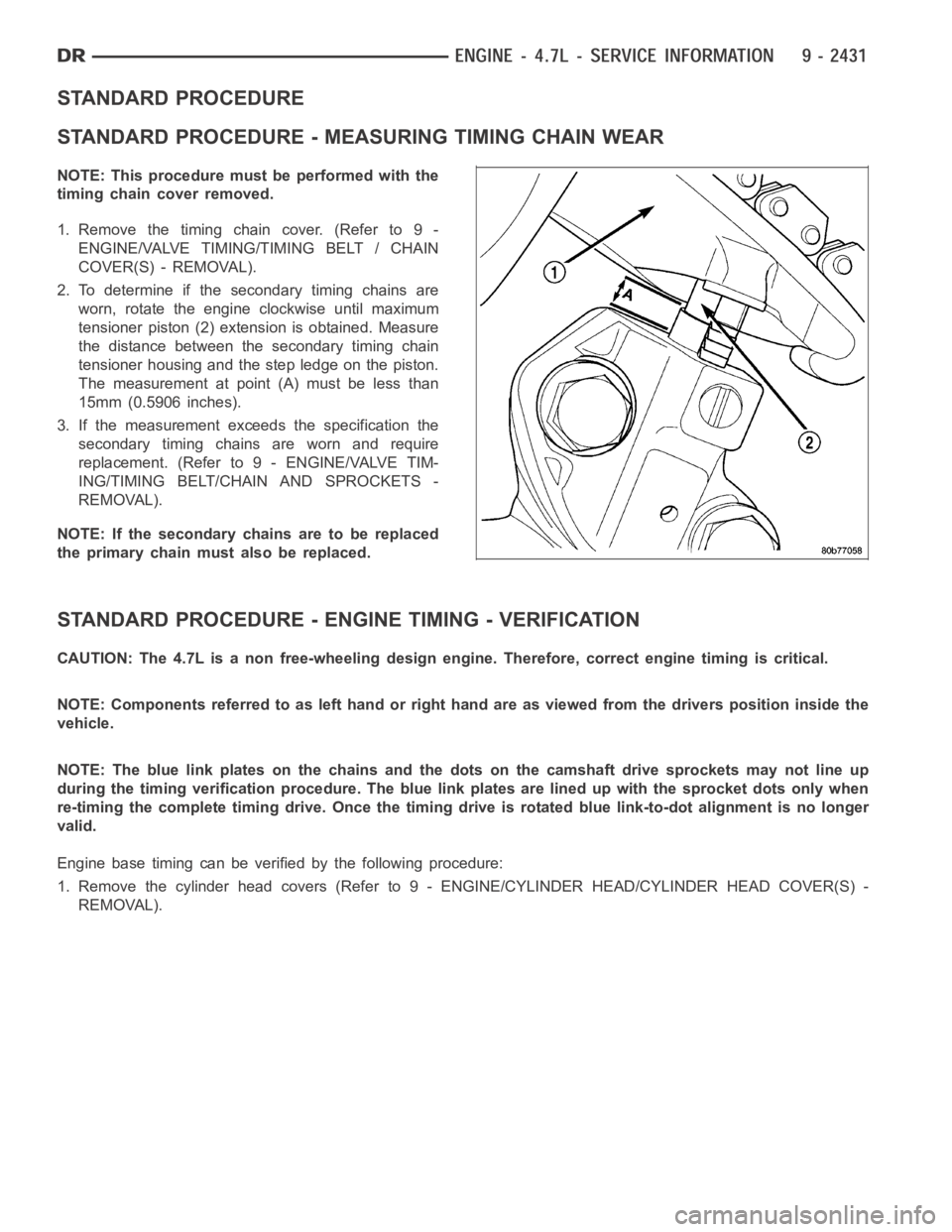
2. To determine if the secondary timing chains are
worn, rotate the engine clockwise until maximum
tensioner piston (2) extension is obtained. Measure
the distance between the secondary timing chain
tensioner housing and the step ledge on the piston.
The measurement at point (A) must be less than
15mm (0.5906 inches).
3. If the measurement exceeds the specification the
secondary timing chains are worn and require
replacement. (Refer to 9 - ENGINE/VALVE TIM-
ING/TIMING BELT/CHAIN AND SPROCKETS -
REMOVAL).
NOTE: If the secondary chains are to be replaced
the primary chain must also be replaced.
STANDARD PROCEDURE - ENGINE TIMING - VERIFICATION
CAUTION: The 4.7L is a non free-wheeling design engine. Therefore, correct engine timing is critical.
NOTE: Components referred to as left hand or right hand are as viewed from thedriverspositioninsidethe
vehicle.
NOTE: The blue link plates on the chains and the dots on the camshaft drive sprockets may not line up
during the timing verification procedure. The blue link plates are lined up with the sprocket dots only when
re-timing the complete timing drive.Once the timing drive is rotated bluelink-to-dot alignment is no longer
valid.
Engine base timing can be verified by the following procedure:
1. Remove the cylinder head covers (Refer to 9 - ENGINE/CYLINDER HEAD/CYLINDERHEADCOVER(S)-
REMOVAL).
Page 1805 of 5267
VALVES & SEATS - INTAKE/EXHAUST
DESCRIPTION
DESCRIPTION - VALVE GUIDES
The valve guides are made of powdered metal and are pressed into the cylinder head. The guides are not replace-
able or serviceable, and valve guide reaming is not recommended. If the guides are worn beyond acceptable limits,
replace the cylinder heads.
DESCRIPTION
Both the intake and exhaust valves are made of steel. The intake valve is 50.93 mm (2.00 inches) in diameter and
the exhaust valve is 39.53 mm (1.55 inches) in diameter. All valves use three bead lock keepers to retain the
springs and promote valve rotation.
STANDARD PROCEDURE - REFACING
NOTE: Valve seats that are worn or burned can be reworked, provided that correct angle and seat width are
maintained. Otherwise the cylinder head must be replaced.
NOTE: When refacing valves and valve seats, it is important that the correct size valve guide pilot be used
for reseating stones. A true and complete surface must be obtained.
1. Using a suitable dial indicator measure the center of the valve seat Total run out must not exceed 0.051 mm
(0.002 in).
2. Apply a small amount of Prussian blue to the valve seat, insert the valve into the cylinder head, while applying
light pressure on the valve rotate the valve. Remove the valve and examine the valve face. If the blue is trans-
ferred below the top edge of the valve face, lower the valve seat using a 15 degree stone. If the blue is trans-
ferred to the bottom edge of the valve face, raise the valve seat using a 65 degree stone.
3. When the seat is properly positioned the width of the intake seat must be 1.018 - 1.62 mm (0.0464 - 0.0637 in.)
and the exhaust seat must be 1.48 - 1.92 mm (0.058 - 0.075 in.).
4. Check the valve spring installed height after refacing the valve and seat.Theinstalledheightforbothintakeand
exhaust valve springs must not exceed 46.0 mm (1.81 in.).
VALVE FACE AND VALVE SEAT ANGLE CHART
DESCRIPTION SPECIFICATION
SEAT WIDTH
INTAKE 1.018 - 1.62 mm
(0.0464 - 0.0637 in.)
EXHAUST 1.48 - 1.92 mm
(0.058 - 0.075 in.)
FA C E A N G L E
(INT. AND EXT.) 45° - 45
1⁄2°
SEAT ANGLE
(INT. AND EXT.) 44
1⁄2° - 45°
Page 1910 of 5267

EXCESSIVE WHITE SMOKE
POSSIBLE CAUSE CORRECTION
Fuel filter plugged. Refer to Powertrain Diagnostic Manual for fuel system
testing.
Fuel grade not correct or fuel quality is poor. Temporarily change fuel brands and note condition.
Change brand if necessary.
Fuel heater element or fuel heater temperature sensor
malfunctioning. This will cause wax type build-up in fuel
filter.Refer to Fuel Heater Testing (Refer to 14 - FUEL
SYSTEM/FUEL DELIVERY/FUEL HEATER -
DIAGNOSIS AND TESTING).
Fuel injector malfunctioning. A DTC should have been set. Perform “Cylinder
Performance Test
orCylinder cutout Testusing DRB
scan tool to isolate individual cylinders. Also refer to
Powertrain Diagnostic Procedures Information and,
(Refer to 14 - FUEL SYSTEM/FUEL INJECTION/FUEL
INJECTOR - DIAGNOSIS AND TESTING).
Fuel injector hold-downs loose. Torque to specifications.
Fuel injector protrusion not correct. Check washer (shim) at bottom of fuel injector for
correct thickness. (Referto 14 - FUEL SYSTEM/FUEL
INJECTION/FUEL INJECTOR - INSTALLATION)
Fuel injection pump malfunctioning. A DTC should have been set. Refer to Powertrain
Diagnostic Procedures Information.
Fuel supply side restriction. Refer to Powertrain Diagnostic Manual for fuel system
testing.
Fuel transfer (lift) pump malfunctioning. A DTC may have been set. Refer toPowertrain
Diagnostic Procedures Information.
Intake/Exhaust valve adjustments not correct (too tight). (Refer to 9 - ENGINE/CYLINDER HEAD/INTAKE/
EXHAUST VALVES & SEATS - STANDARD
PROCEDURE).
Intake manifold air temperature sensor malfunctioning. A DTC should havebeen set. Refer to Powertrain
Diagnostic Procedures Information.
Intake manifold heater circuit not functioning correctly in
cold weather.A DTC should have been set. Refer to Powertrain
Diagnostic Procedures Information. Also check heater
elements for correct operation.
Intake manifold heater elements not functioning
correctly in cold weather.A DTC should have been set if heater elements are
malfunctioning. Refer to Powertrain Diagnostic
Procedures Information.
Internal engine damage (scuffed cylinder). Analyze engine oil and inspect oil filter to locate area of
probable damage.
Restriction in fuel supply side of fuel system. Refer to Powertrain Diagnostic Manual for fuel system
testing.
EXCESSIVE BLUE SMOKE
POSSIBLE CAUSE CORRECTION
Dirty air cleaner or restricted turbocharger intake duct. Check Filter Minder
at air filter housing. (Refer to 9 -
ENGINE/AIR INTAKE SYSTEM/AIR CLEANER
ELEMENT - REMOVAL).
Air leak in boost system between turbocharger
compressor outlet and intake manifold.Service air charge system..
Obstruction in exhaust manifold. Remove exhaust manifold and inspect forblockage
(Refer to 9 - ENGINE/MANIFOLDS/EXHAUST
MANIFOLD - REMOVAL).
Page 1911 of 5267
EXCESSIVE BLUE SMOKE
POSSIBLE CAUSE CORRECTION
Restricted turbocharger drain tube. Remove turbocharger drain tube and remove
obstruction.
Crankcase ventilation system plugged. Inspect crankcase ventilation system for function
Valve seals are worn, brittle, or improperly installed. Replace valve stemoilseals(Referto9-ENGINE/
CYLINDER HEAD/INTAKE/EXHAUST VALVES &
SEATS - REMOVAL).
Valve stems and/or guides are worn. Remove valves and inspect valves and guides. (Refer
to 9 - ENGINE/CYLINDER HEAD/INTAKE/EXHAUST
VALVES & SEATS - STANDARD PROCEDURE).
Broken or Improperly installed piston rings. Tear down engine and inspectpiston rings.
Excessive piston ring end gap. Remove pistons and measure piston ring end gap
(Refer to 9 - ENGINE/ENGINE BLOCK/PISTON RINGS
- STANDARD PROCEDURE).
Excessive cylinder bore wear and taper. Remove pistons and measure cylinder bore wear and
taper (Refer to 9 - ENGINE/ENGINE BLOCK -
STANDARD PROCEDURE).
Cylinder damage. Remove pistons and inspect cylinder bore for cracks or
porosity. Repair with cylinder liner if necessary. (Refer
to 9 - ENGINE/ENGINE BLOCK - STANDARD
PROCEDURE).
Piston damage. Remove pistons and inspect for cracks, holes. Measure
piston for out-of-round and taper (Refer to 9 -
ENGINE/ENGINE BLOCK/PISTON & CONNECTING
ROD - INSPECTION).
Turbocharger failure. (Refer to 11 - EXHAUST SYSTEM/TURBOCHARGER
SYSTEM/TURBOCHARGER - INSPECTION).
DIAGNOSIS AND TESTING - CYLINDER COMPRESSION/LEAKAGE TESTS
CYLINDER COMPRESSION PRESSURE
The results of a cylinder compressionpressure test can be utilized to diagnose several engine malfunctions.
Ensure batteries are completely charged and the engine starter motor is ingood operating condition. Otherwise, the
indicated compression pressures may not be valid for diagnostic purposes.
1. Disconnect the fuel inlet line to the fuel filter housing. Plug the fuel line from the fuel tank.
NOTE: Failure to plug fuel line will result in fuel leak.
2. Remove fuel transfer pump relay from PDC.
3. Start the engine and idle until the engine stalls (runs out of fuel).
4. Remove the cylinder head cover. (Refer to 9 - ENGINE/CYLINDER HEAD/CYLINDER HEAD COVER(S) -
REMOVAL)
5. Remove the cylinder head cover carrier gasket. (Refer to 9 - ENGINE/CYLINDER HEAD/CYLINDER HEAD
COVER(S) - REMOVAL)
6. Remove the high pressure fuel line between the cylinder head and fuel rail for the cylinder to be tested. Use
tool# 9011 to cap this fuel rail on the cylinder being tested.
7. Remove the fuel connector tube nut and fuel connector tube.
8. Remove the exhaust rocker lever.
9. Use Tool 9010 to remove the injector and copper sealing washer.
10. Install the exhaust rocker lever and torque to 36 Nꞏm (27 ft. lbs.).
11. Cover the remaining rocker levers with clean shop towels to prevent anyoil splatter under the hood.
Page 2027 of 5267
CONDITION POSSIBLE CAUSES CORRECTION
EXCESSIVE OIL
CONSUMPTION OR
SPARK PLUGS OIL
FOULED1. PCV system malfunction. 1. Check and repair PCV system as
necessary.
2. Defective valve stem seal(s). 2. Repair or replace seal(s).
3. Worn or broken piston rings. 3. Hone cylinder bores. Install new rings.
4. Scuffed pistons/cylinder walls. 4. Hone cylinder bores and replace pistons
as necessary.
5. Carbon in oil control ring groove. 5. Remove rings and de-carbon piston.
6. Worn valve guides. 6. Ream and install new valves with
oversize stems.
7. Piston rings fitted too tightly in
grooves.7. Remove piston rings. Check ring end
gap and side clearance. Replace as
necessary.
CYLINDER COMPRESSION PRESSURE TEST
The results of a cylinder compressionpressure test can be utilized to diagnose several engine malfunctions.
Ensurethebatteryiscompletelychargedandtheenginestartermotorisingood operating condition. Otherwise the
indicated compression pressures may not be valid for diagnosis purposes.
1. Check engine oil level and add oil if necessary.
2. Drive the vehicle until engine reaches normal operating temperature. Select a route free from traffic and other
forms of congestion, observe all traffic laws, and accelerate through thegears several times briskly.
3. Remove the Auto Shut Down (ASD) relay from the Power Distribution Center(PDC).
4. Disconnect ignition cables from spark plugs.
5. Remove all spark plugs from engine. As spark plugs are being removed, check electrodes for abnormal firing
indicators fouled, hot, oily, etc. Record cylinder number of spark plug for future reference.
6. Be sure throttle blade is fully open during the compression check.
7. Insert compression gauge adaptor Special Tool 8116 or the equivalent, into the No. 1 spark plug hole in cylinder
head. Connect the 0-500 psi (Blue) pressure transducer (Special Tool CH7059) with cable adaptors to the scan
tool. For Special Tool identification, (Refer to 9 - ENGINE - SPECIAL TOOLS).
8. Crank engine until maximum pressure is reached on gauge. Record this pressure as No. 1 cylinder pressure.
9. Repeat the previous step for all remaining cylinders.
10. Compression should not be less than 689 kPa (100 psi) and not vary more than 25 percent from cylinder to
cylinder.
11. If one or more cylinders have abnormally low compression pressures, repeat the compression test.
12. If the same cylinder or cylinders repeat an abnormally low reading on the second compression test, it could
indicate the existence of a problem in the cylinder in question.The recommended compression pressures
are to be used only as a guide to diagnosing engine problems. An engine should not be disassembled
to determine the cause of low compression unless some malfunction is present.
CYLINDER COMBUSTIONPRESSURE LEAKAGE TEST
The combustion pressure leakage test provides an accurate means for determining engine condition.
Combustion pressure leakage testing will detect:
Exhaust and intake valve leaks (improper seating).
Leaks between adjacent cylinders or into water jacket.
Any causes for combustion/compression pressure loss.
WARNING: Do not remove the cooling system pressure cap with the system hot and under pressure
because serious burns from coolant can occur.
1. Check the coolant level and fill as required. DO NOT install the pressurecap.
2. Start and operate the engine until it attains normal operating temperature, then turn the engine OFF.
Page 2075 of 5267
INTAKE/EXHAUST - VALVES/SEATS/GUIDES
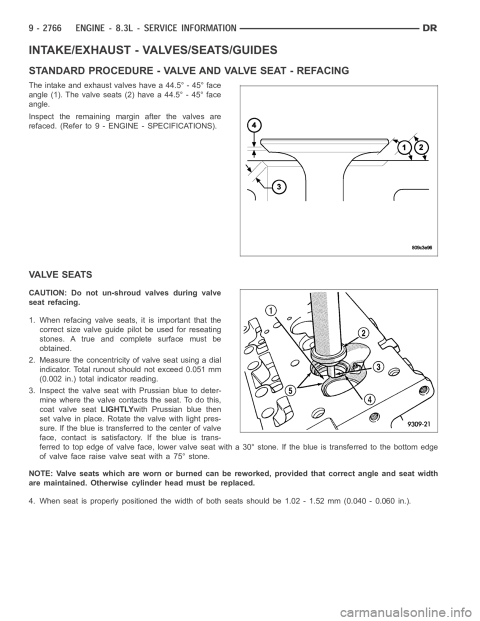
STANDARD PROCEDURE - VALVE AND VALVE SEAT - REFACING
The intake and exhaust valves have a 44.5° - 45° face
angle (1). The valve seats (2) have a 44.5° - 45° face
angle.
Inspect the remaining margin after the valves are
refaced. (Refer to 9 - ENGINE - SPECIFICATIONS).
VALVE SEATS
CAUTION: Do not un-shroud valves during valve
seat refacing.
1. When refacing valve seats, it is important that the
correct size valve guide pilot be used for reseating
stones. A true and complete surface must be
obtained.
2. Measure the concentricity of valve seat using a dial
indicator. Total runout should not exceed 0.051 mm
(0.002 in.) total indicator reading.
3. Inspect the valve seat with Prussian blue to deter-
mine where the valve contacts the seat. To do this,
coat valve seatLIGHTLYwith Prussian blue then
set valve in place. Rotate the valve with light pres-
sure. If the blue is transferred to the center of valve
face, contact is satisfactory. If the blue is trans-
ferred to top edge of valve face, lower valve seat with a 30° stone. If the blue is transferred to the bottom edge
of valve face raise valve seat with a 75° stone.
NOTE: Valve seats which are worn or burned can be reworked, provided that correct angle and seat width
are maintained. Otherwise cylinder head must be replaced.
4. When seat is properly positioned the width of both seats should be 1.02 - 1.52 mm (0.040 - 0.060 in.).
Page 2352 of 5267
HEATER-FUEL
DESCRIPTION
The fuel heater assembly is located on the side of the fuel filter housing and internal to the fuel filter housing .
The heater/element assembly is equipped with a temperature sensor (thermostat) that senses fuel temperature. This
sensor is attached to the fuel heater/element assembly.
OPERATION
The fuel heater is used to prevent diesel fuel from waxing during cold weather operation.
When the fuel temperature is below 45° ±8 F (7°C), the temperature sensor allows current to flow to the heater
element warming the fuel. When the fuel temperature is above 75° ±8 F (24°C), the sensor stops current flow to the
heater element.
Battery voltage to operate the fuel heater element is supplied from the ignition switch and through a solid stated
device in the IPM.The fuel heater element and
solid state device in IPMinstead offuel heater relayare not
computer controlled.
The heater element operates on 12 volts, 300 watts at 0° F (-18° C).
DIAGNOSIS AND TESTING
FUEL HEATER
The fuel heater is used to prevent diesel fuel from waxing during cold weather operation.
NOTE: The fuel heater element,
solid state device in IPMinstead offuel heater relayand fuel heater tem-
perature sensor are not controlled by the Engine Control Module (ECM).
A malfunctioning fuel heater can cause a wax build-up in the fuel filter/water separator. Wax build-up in the filter/
separator can cause engine starting problems and prevent the engine from revving up. It can also cause blue or
white fog-like exhaust. If the heater is not operating in cold temperatures, the engine may not operate due to fuel
waxing.
The fuel heater assembly is located on the side of fuel filter housing and internal to the fuel filter housing.
The heater assembly is equipped with a built-in fuel temperature sensor (thermostat) that senses fuel temperature.
When fuel temperature drops below 45° ± 8° F (7° C), the sensor allows current to flow to built-in heater element
to warm fuel. When fuel temperature rises above 75 °± 8° F (24° C), the sensorstops current flow to heater ele-
ment (circuit is open).
Voltage to operate fuel heater element is supplied from ignition switch, through
solid state device in IPM,tofuel
temperature sensor and on to fuel heater element.
The heater element operates on 12 volts, 300 watts at 0 °F (-18° C). As temperature increases, power requirements
decrease.
A minimum of 7 volts is required to operate the fuel heater. The resistance value of the heater element is less than
1 ohm (cold) and up to 1000 ohms warm.
TESTING
1. Disconnect electrical connector from thermostat.
Ambient temperature must be below the circuit close temperature. If necessary, induce this ambient temperature by
placing ice packs on thermostat to produce an effective ambient temperature below circuit close temperature.
Measure resistance across two pins. Operating range is 0.3 - 0.45 Ohms.
2. If resistance is out of range, remove thermostat and check resistance across terminal connections of heater. The
heater can be checked at room temperature. Operating range is 0.3 - 0.45 Ohms.
3. Replace heater if resistance is not within operating range.
4. If heater is within operating range, replace heater thermostat.
Page 4553 of 5267
PA I N T
SPECIFICATIONS
PA I N T C O D E S
CAUTION: Due to possible late model change of paint colors, always check each vehicle for its paint
code(s) (Refer to VEHICLE DATA/VEHICLE INFORMATION/VEHICLE CERTIFICATION LABEL - DESCRIPTION)
or (Refer to VEHICLE DATA/VEHICLE INFORMATION/BODY CODE PLATE - DESCRIPTION) and (Refer to 23 -
BODY/PAINT/PAINT CODE - DESCRIPTION).
EXTERIOR COLORS
EXTERIOR COLOR DAIMLERCHRYSLER CODE
Inferno Red Crystal Pearlcoat ARH/ARJ
Flame Red Clearcoat PR4
Light Khaki Clearcoat AJC
Atlantic Blue Pearlcoat ZBJ
Patriot Blue Pearlcoat WBT/WB7
Bright Silver Metallic Clearcoat WSB/WS2
Mineral Gray Metallic Clearcoat CDM
Black Clearcoat DX8
Bright White Clearcoat GW7
INTERIOR COLORS
INTERIOR COLOR DAIMLERCHRYSLER CODE
Medium Slate Gray D5
Khaki J3