2006 DODGE RAM SRT-10 ad blue
[x] Cancel search: ad bluePage 1197 of 5267
- Internal engine component failures.
Were any of the above conditions present?
Ye s>>
Repair as necessary.
Perform the POWERTRAIN VERIFICATION TEST. (Refer to 9 - ENGINE - STANDARD PROCEDURE)
No>>
Go To 3
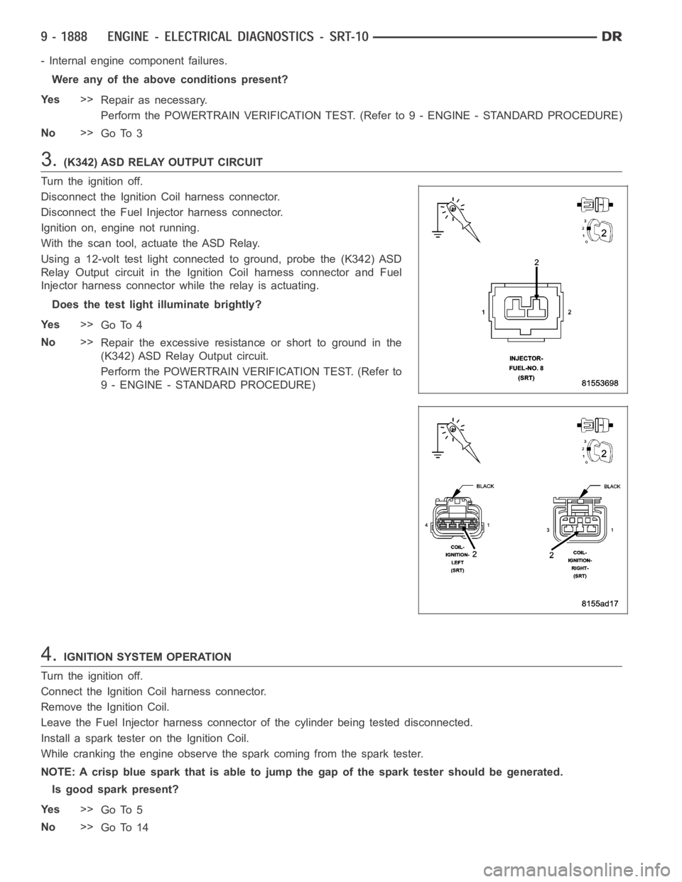
3.(K342) ASD RELAY OUTPUT CIRCUIT
Turn the ignition off.
Disconnect the Ignition Coil harness connector.
Disconnect the Fuel Injector harness connector.
Ignition on, engine not running.
With the scan tool, actuate the ASD Relay.
Using a 12-volt test light connected to ground, probe the (K342) ASD
Relay Output circuit in the Ignition Coil harness connector and Fuel
Injector harness connector while the relay is actuating.
Does the test light illuminate brightly?
Ye s>>
Go To 4
No>>
Repair the excessive resistanceorshorttogroundinthe
(K342) ASD Relay Output circuit.
Perform the POWERTRAIN VERIFICATION TEST. (Refer to
9 - ENGINE - STANDARD PROCEDURE)
4.IGNITION SYSTEM OPERATION
Turn the ignition off.
Connect the Ignition Coil harness connector.
Remove the Ignition Coil.
Leave the Fuel Injector harness connector of the cylinder being tested disconnected.
Install a spark tester on the Ignition Coil.
While cranking the engine observe the spark coming from the spark tester.
NOTE: A crisp blue spark that is able tojump the gap of the spark tester should be generated.
Is good spark present?
Ye s>>
Go To 5
No>>
Go To 14
Page 1206 of 5267
- Internal engine component failures.
Were any of the above conditions present?
Ye s>>
Repair as necessary.
Perform the POWERTRAIN VERIFICATION TEST. (Refer to 9 - ENGINE - STANDARD PROCEDURE)
No>>
Go To 3
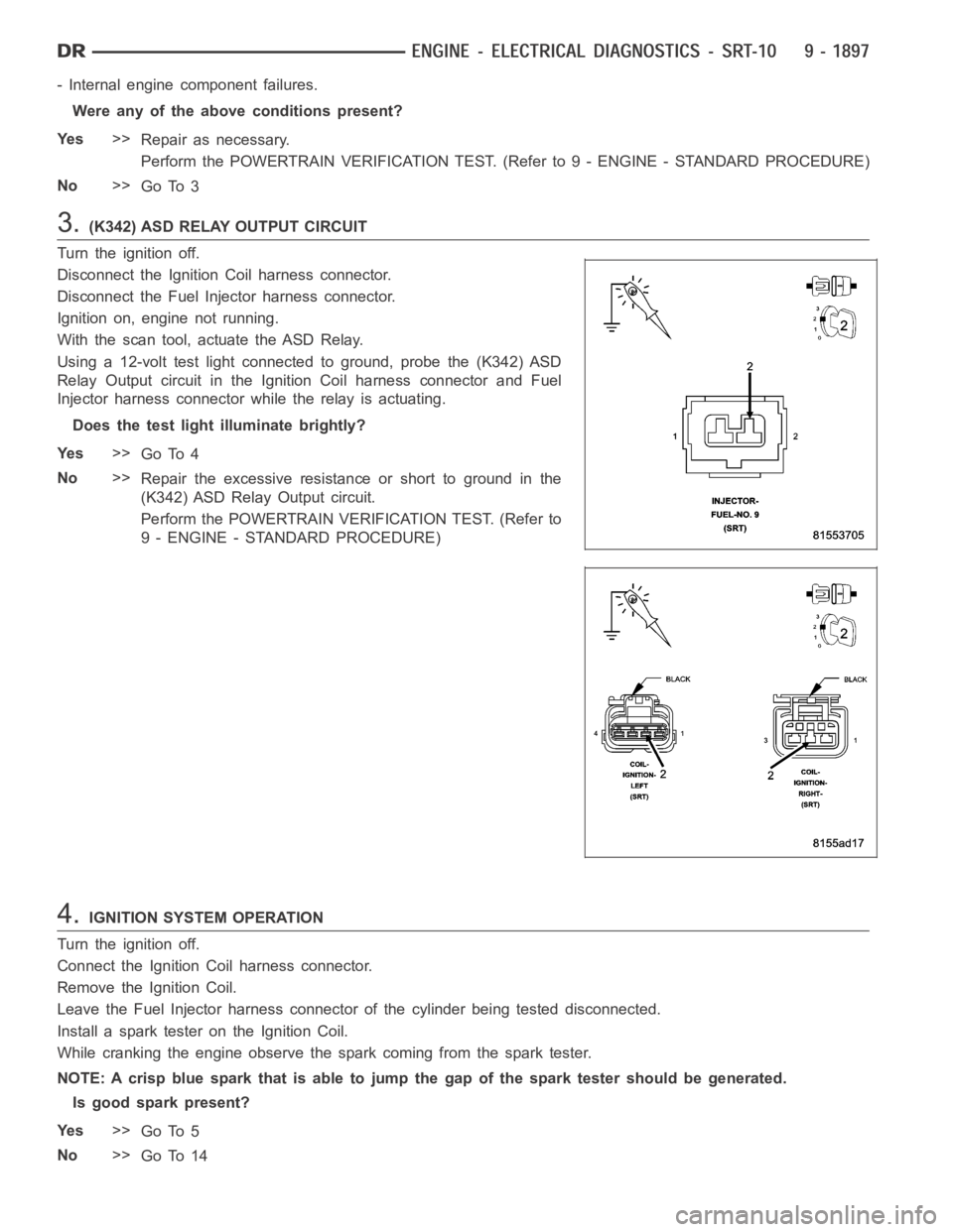
3.(K342) ASD RELAY OUTPUT CIRCUIT
Turn the ignition off.
Disconnect the Ignition Coil harness connector.
Disconnect the Fuel Injector harness connector.
Ignition on, engine not running.
With the scan tool, actuate the ASD Relay.
Using a 12-volt test light connected to ground, probe the (K342) ASD
Relay Output circuit in the Ignition Coil harness connector and Fuel
Injector harness connector while the relay is actuating.
Does the test light illuminate brightly?
Ye s>>
Go To 4
No>>
Repair the excessive resistanceorshorttogroundinthe
(K342) ASD Relay Output circuit.
Perform the POWERTRAIN VERIFICATION TEST. (Refer to
9 - ENGINE - STANDARD PROCEDURE)
4.IGNITION SYSTEM OPERATION
Turn the ignition off.
Connect the Ignition Coil harness connector.
Remove the Ignition Coil.
Leave the Fuel Injector harness connector of the cylinder being tested disconnected.
Install a spark tester on the Ignition Coil.
While cranking the engine observe the spark coming from the spark tester.
NOTE: A crisp blue spark that is able tojump the gap of the spark tester should be generated.
Is good spark present?
Ye s>>
Go To 5
No>>
Go To 14
Page 1215 of 5267
- Internal engine component failures.
Were any of the above conditions present?
Ye s>>
Repair as necessary.
Perform the POWERTRAIN VERIFICATION TEST. (Refer to 9 - ENGINE - STANDARD PROCEDURE)
No>>
Go To 3
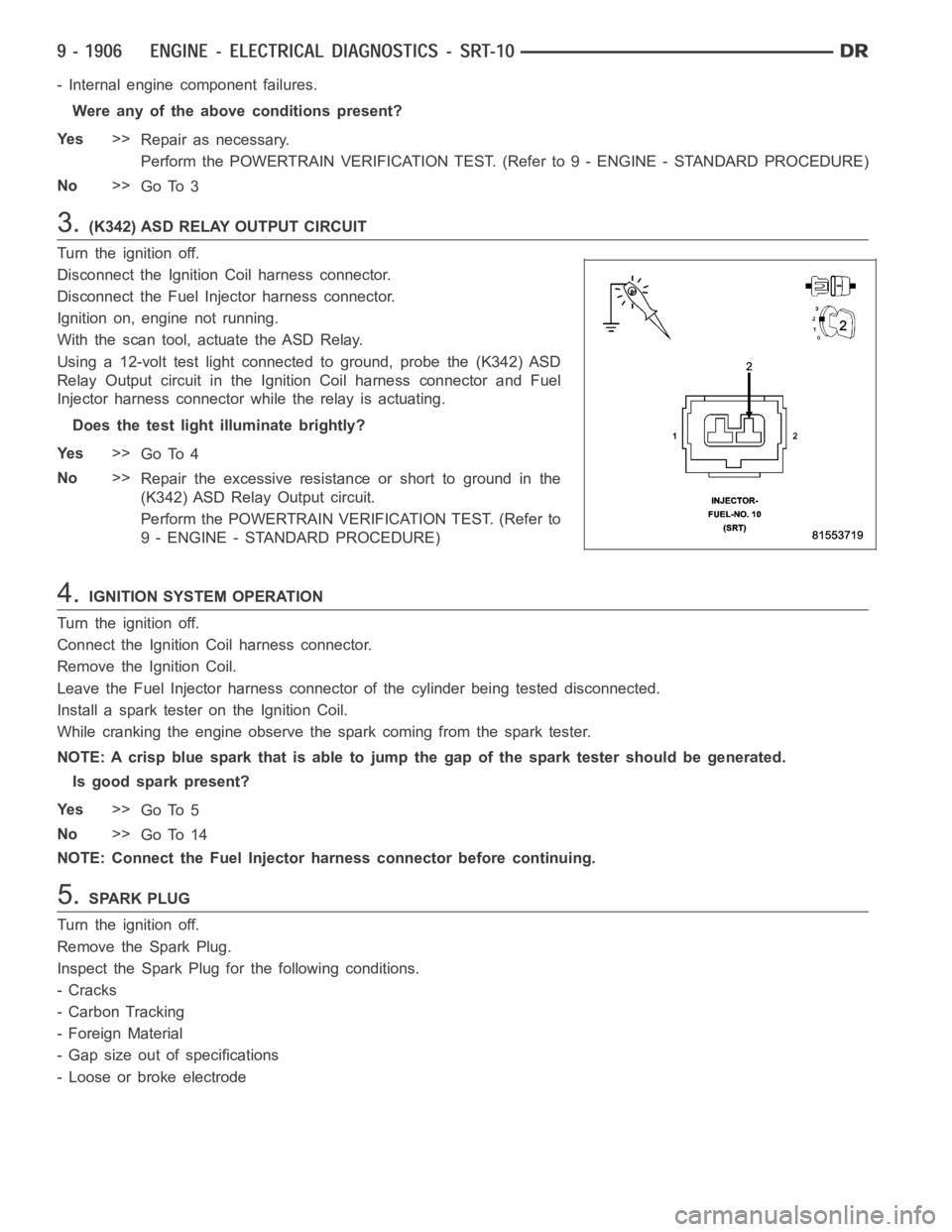
3.(K342) ASD RELAY OUTPUT CIRCUIT
Turn the ignition off.
Disconnect the Ignition Coil harness connector.
Disconnect the Fuel Injector harness connector.
Ignition on, engine not running.
With the scan tool, actuate the ASD Relay.
Using a 12-volt test light connected to ground, probe the (K342) ASD
Relay Output circuit in the Ignition Coil harness connector and Fuel
Injector harness connector while the relay is actuating.
Does the test light illuminate brightly?
Ye s>>
Go To 4
No>>
Repair the excessive resistanceorshorttogroundinthe
(K342) ASD Relay Output circuit.
Perform the POWERTRAIN VERIFICATION TEST. (Refer to
9 - ENGINE - STANDARD PROCEDURE)
4.IGNITION SYSTEM OPERATION
Turn the ignition off.
Connect the Ignition Coil harness connector.
Remove the Ignition Coil.
Leave the Fuel Injector harness connector of the cylinder being tested disconnected.
Install a spark tester on the Ignition Coil.
While cranking the engine observe the spark coming from the spark tester.
NOTE: A crisp blue spark that is able tojump the gap of the spark tester should be generated.
Is good spark present?
Ye s>>
Go To 5
No>>
Go To 14
NOTE: Connect the Fuel Injector harness connector before continuing.
5.SPARK PLUG
Turn the ignition off.
Remove the Spark Plug.
Inspect the Spark Plug for the following conditions.
-Cracks
- Carbon Tracking
- Foreign Material
- Gap size out of specifications
- Loose or broke electrode
Page 1528 of 5267
VALVES & SEATS - INTAKE/EXHAUST
DESCRIPTION
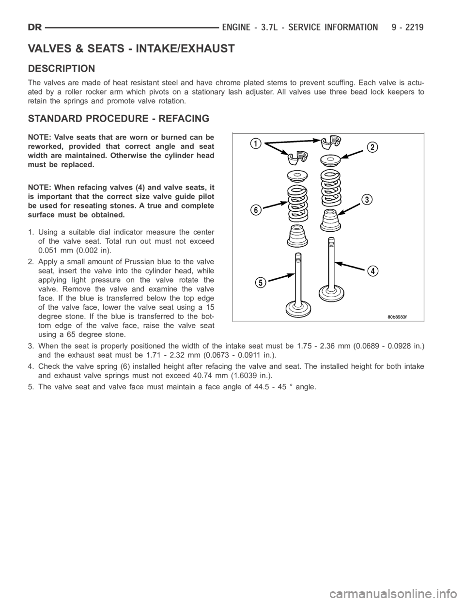
The valves are made of heat resistant steel and have chrome plated stems to prevent scuffing. Each valve is actu-
ated by a roller rocker arm which pivots on a stationary lash adjuster. All valves use three bead lock keepers to
retain the springs and promote valve rotation.
STANDARD PROCEDURE - REFACING
NOTE: Valve seats that are worn or burned can be
reworked, provided that correct angle and seat
width are maintained. Otherwise the cylinder head
must be replaced.
NOTE: When refacing valves (4) and valve seats, it
is important that the correct size valve guide pilot
be used for reseating stones. A true and complete
surface must be obtained.
1. Using a suitable dial indicator measure the center
of the valve seat. Total run out must not exceed
0.051 mm (0.002 in).
2. Apply a small amount of Prussian blue to the valve
seat, insert the valve into the cylinder head, while
applying light pressure on the valve rotate the
valve. Remove the valve and examine the valve
face. If the blue is transferred below the top edge
of the valve face, lower the valve seat using a 15
degree stone. If the blue is transferred to the bot-
tom edge of the valve face, raise the valve seat
using a 65 degree stone.
3. When the seat is properly positioned the width of the intake seat must be 1.75 - 2.36 mm (0.0689 - 0.0928 in.)
and the exhaust seat must be 1.71 - 2.32 mm (0.0673 - 0.0911 in.).
4. Check the valve spring (6) installed height after refacing the valve andseat. The installed height for both intake
and exhaust valve springs must not exceed 40.74 mm (1.6039 in.).
5. The valve seat and valve face must maintain a face angle of 44.5 - 45 ° angle.
Page 1557 of 5267
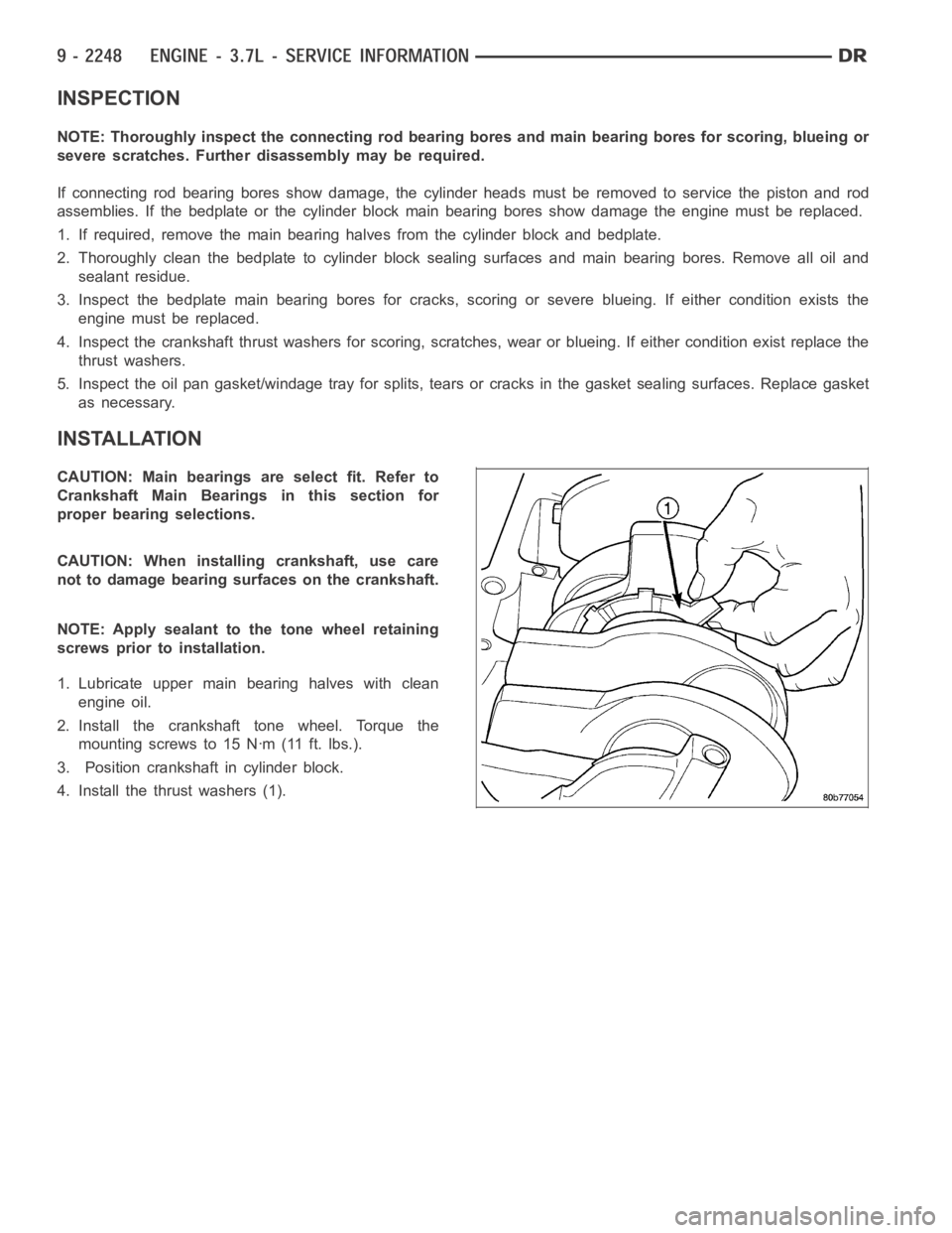
INSPECTION
NOTE: Thoroughly inspect the connecting rod bearing bores and main bearing bores for scoring, blueing or
severe scratches. Further disassembly may be required.
If connecting rod bearing bores show damage, the cylinder heads must be removed to service the piston and rod
assemblies. If the bedplate or the cylinder block main bearing bores show damage the engine must be replaced.
1. If required, remove the main bearing halves from the cylinder block and bedplate.
2. Thoroughly clean the bedplate to cylinder block sealing surfaces and main bearing bores. Remove all oil and
sealant residue.
3. Inspect the bedplate main bearing bores for cracks, scoring or severe blueing. If either condition exists the
engine must be replaced.
4. Inspect the crankshaft thrust washers for scoring, scratches, wear or blueing. If either condition exist replace the
thrust washers.
5. Inspect the oil pan gasket/windage tray for splits, tears or cracks in the gasket sealing surfaces. Replace gasket
as necessary.
INSTALLATION
CAUTION: Main bearings are select fit. Refer to
Crankshaft Main Bearings in this section for
proper bearing selections.
CAUTION: When installing crankshaft, use care
not to damage bearing surfaces on the crankshaft.
NOTE: Apply sealant to the tone wheel retaining
screws prior to installation.
1. Lubricate upper main bearing halves with clean
engine oil.
2. Install the crankshaft tone wheel. Torque the
mountingscrewsto15Nꞏm(11ft.lbs.).
3. Position crankshaft in cylinder block.
4. Install the thrust washers (1).
Page 1607 of 5267
loads. Each tensioner also has a mechanical ratchet system that limits chain slack if the tensioner piston bleeds
down after engine shut down. The tensioner arms and guides also utilize nylon wear faces for low friction and long
wear. The secondary timing chains receive lubrication from a small orifice in the tensioners. This orifice is protected
from clogging by a fine mesh screen which is located on the back of the hydraulic tensioners.
STANDARD PROCEDURE
MEASURING TIMING CHAIN WEAR
NOTE: This procedure must be performed with the
timing chain cover removed.
1. Remove the timing chain cover (Refer to 9 -
ENGINE/VALVE TIMING/TIMING BELT/CHAIN
AND SPROCKETS - REMOVAL).
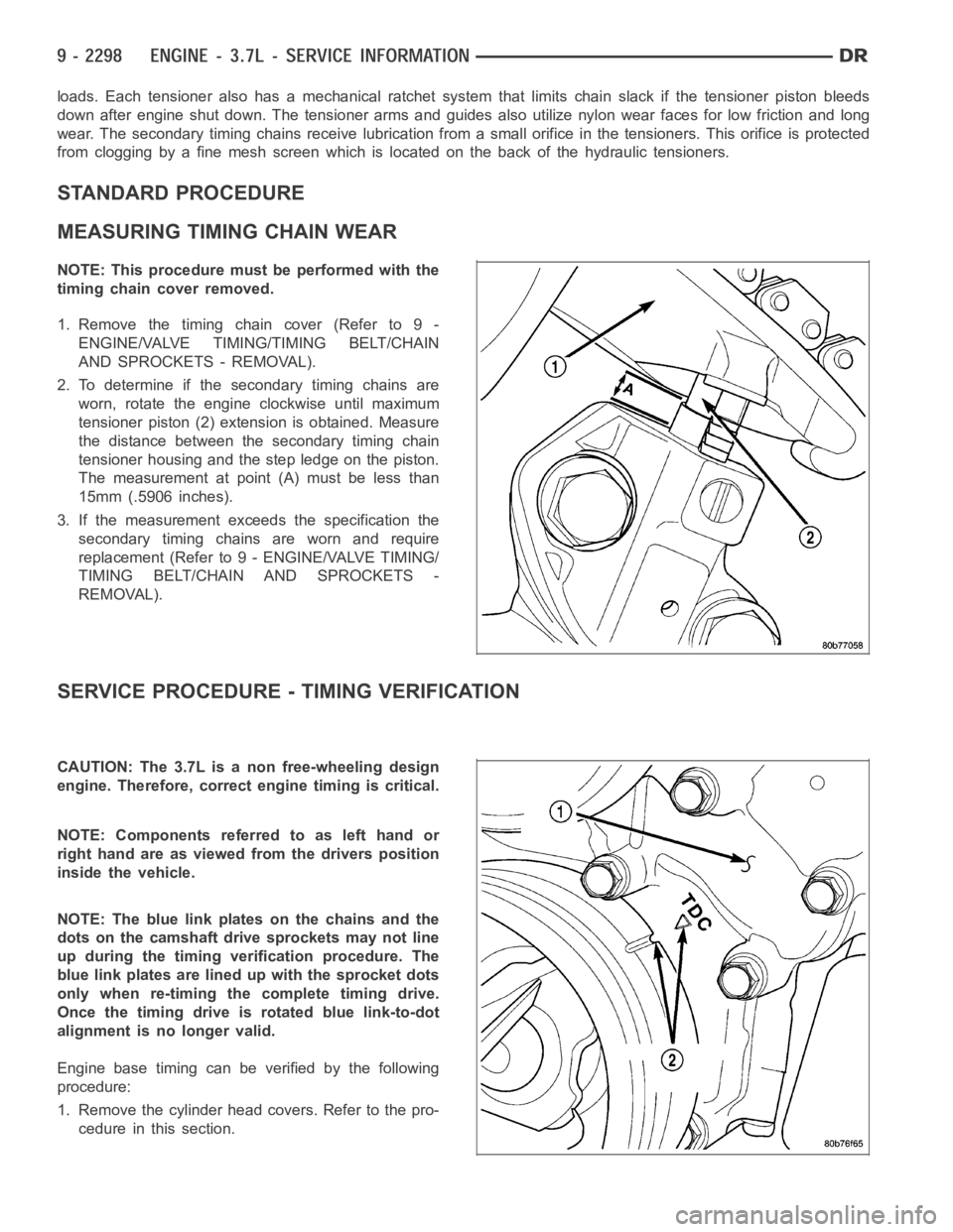
2. To determine if the secondary timing chains are
worn, rotate the engine clockwise until maximum
tensioner piston (2) extension is obtained. Measure
the distance between the secondary timing chain
tensioner housing and the step ledge on the piston.
The measurement at point (A) must be less than
15mm (.5906 inches).
3. If the measurement exceeds the specification the
secondary timing chains are worn and require
replacement (Refer to 9 - ENGINE/VALVE TIMING/
TIMING BELT/CHAIN AND SPROCKETS -
REMOVAL).
SERVICE PROCEDURE - TIMING VERIFICATION
CAUTION: The 3.7L is a non free-wheeling design
engine. Therefore, correct engine timing is critical.
NOTE:Componentsreferredtoaslefthandor
right hand are as viewed from the drivers position
inside the vehicle.
NOTE: The blue link plates on the chains and the
dots on the camshaft drive sprockets may not line
up during the timing verification procedure. The
blue link plates are lined up with the sprocket dots
only when re-timing the complete timing drive.
Once the timing drive is rotated blue link-to-dot
alignment is no longer valid.
Engine base timing can be verified by the following
procedure:
1. Remove the cylinder head covers. Refer to the pro-
cedure in this section.
Page 1695 of 5267
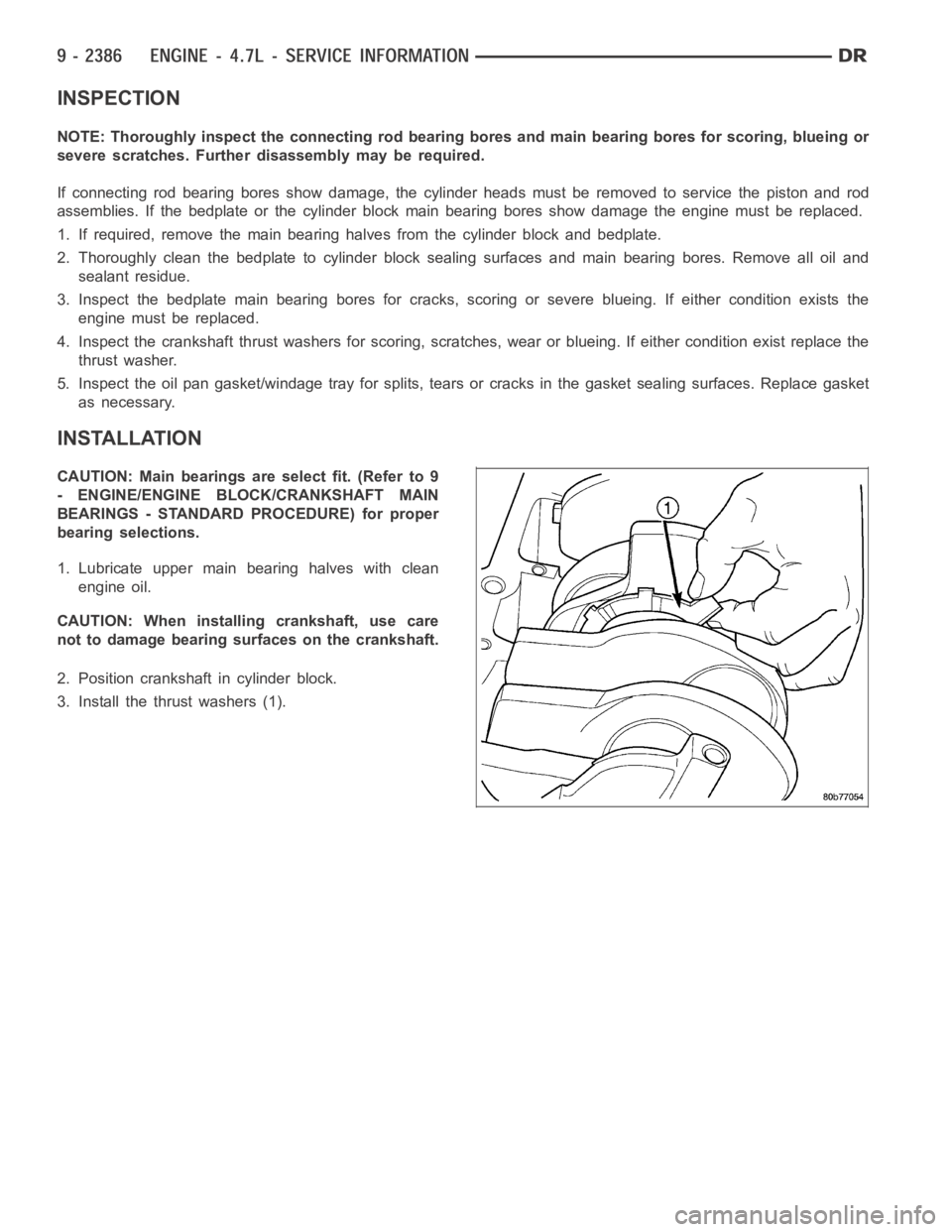
INSPECTION
NOTE: Thoroughly inspect the connecting rod bearing bores and main bearing bores for scoring, blueing or
severe scratches. Further disassembly may be required.
If connecting rod bearing bores show damage, the cylinder heads must be removed to service the piston and rod
assemblies. If the bedplate or the cylinder block main bearing bores show damage the engine must be replaced.
1. If required, remove the main bearing halves from the cylinder block and bedplate.
2. Thoroughly clean the bedplate to cylinder block sealing surfaces and main bearing bores. Remove all oil and
sealant residue.
3. Inspect the bedplate main bearing bores for cracks, scoring or severe blueing. If either condition exists the
engine must be replaced.
4. Inspect the crankshaft thrust washers for scoring, scratches, wear or blueing. If either condition exist replace the
thrust washer.
5. Inspect the oil pan gasket/windage tray for splits, tears or cracks in the gasket sealing surfaces. Replace gasket
as necessary.
INSTALLATION
CAUTION: Main bearings are select fit. (Refer to 9
- ENGINE/ENGINE BLOCK/CRANKSHAFT MAIN
BEARINGS - STANDARD PROCEDURE) for proper
bearing selections.
1. Lubricate upper main bearing halves with clean
engine oil.
CAUTION: When installing crankshaft, use care
not to damage bearing surfaces on the crankshaft.
2. Position crankshaft in cylinder block.
3. Install the thrust washers (1).
Page 1705 of 5267
ROD - PISTON & CONNECTING
DESCRIPTION
CAUTION: Do not use a metal stamp to mark connecting rods as damage may result, instead use ink or a
scratch awl.
Thepistonsaremadeofahighstrengthaluminumalloy.Theanodizedtopring groove and crown has been
replaced with a coated top ring that is blue in color on the bottom surface. Piston skirts are coated with a solid
lubricant (Molykote) to reduce friction and provide scuff resistance. The connecting rods are made of forged pow-
dered metal, with a “fractured cap” design. A pressed fit piston pin is usedto attach the piston and connecting rod.
STANDARD PROCEDURE - PISTON FITTING
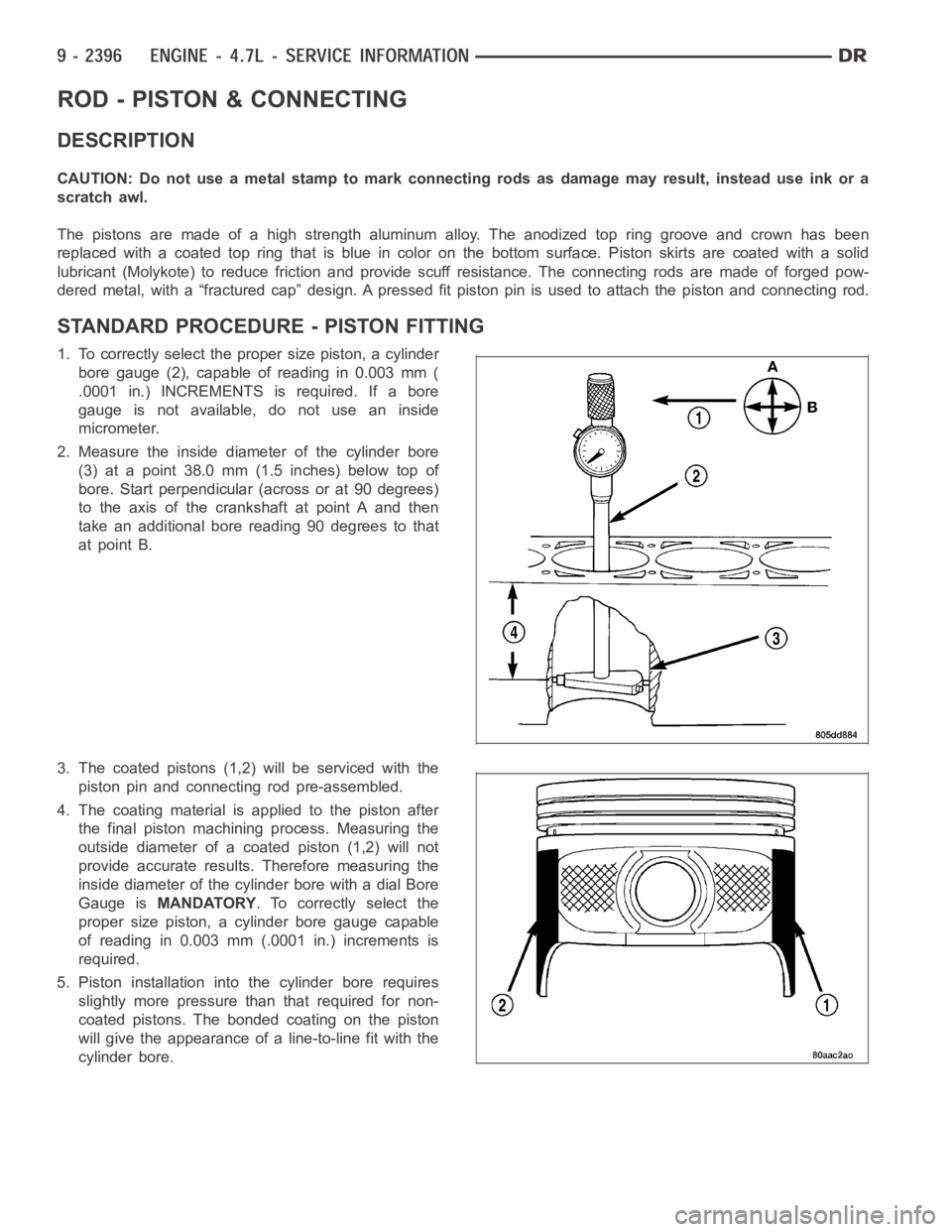
1. To correctly select the proper size piston, a cylinder
bore gauge (2), capable of reading in 0.003 mm (
.0001 in.) INCREMENTS is required. If a bore
gauge is not available, do not use an inside
micrometer.
2. Measure the inside diameter of the cylinder bore
(3) at a point 38.0 mm (1.5 inches) below top of
bore. Start perpendicular (across or at 90 degrees)
to the axis of the crankshaft at point A and then
take an additional bore reading 90 degrees to that
at point B.
3. The coated pistons (1,2) will be serviced with the
piston pin and connecting rod pre-assembled.
4. The coating material is applied to the piston after
the final piston machining process. Measuring the
outside diameter of a coated piston (1,2) will not
provide accurate results. Therefore measuring the
inside diameter of the cylinder bore with a dial Bore
Gauge isMANDATORY. To correctly select the
proper size piston, a cylinder bore gauge capable
of reading in 0.003 mm (.0001 in.) increments is
required.
5. Piston installation intothe cylinder bore requires
slightly more pressure than that required for non-
coated pistons. The bonded coating on the piston
will give the appearance of a line-to-line fit with the
cylinder bore.