2006 DODGE RAM SRT-10 engine
[x] Cancel search: enginePage 3463 of 5267
OPERATION
As the torque converter rotates, the converter hub rotates the oil pump drive gear. As the drive gear rotates both
driven gears, a vacuum is created when the gear teeth come out of mesh. This suction draws fluid through the
pump inlet from the oil pan. As the gear teeth come back into mesh, pressurized fluid is forced into the pump outlet
and to the oil pump valves.
At low speeds, both sides of the pump supply fluid to the transmission. As the speed of the torque converter
increases, the flow from both sides increases until the flow from the primary side alone is sufficient to meet system
demands. At this point, the check valve located between the two pumps closes. The secondary side is shut down
and the primary side supplies all the fluid to the transmission.
CONVERTER CLUTCH SWITCH VALVE
The converter clutch switch valve is used to control the hydraulic pressure supplied to the front (OFF) side of the
torque converter clutch.
CONVERTER CLUTCH REGULATOR VALVE
The converter clutch regulator valve is used to control the hydraulic pressure supplied to the back (ON) side of the
torque converter clutch.
TORQUE CONVERTER LIMIT VALVE
The torque converter limit valve serves to limit the available line pressure to the torque converter clutch.
STANDARD PROCEDURE - OIL PUMP VOLUME CHECK
Measuring the oil pump output volume will determine if sufficient oil flowto the transmission oil cooler exists, and
whether or not an internal transmission failure is present.
Verify that the transmission fluid is at the proper level. Refer to the Fluid Level Check procedure in this section. If
necessary, fill the transmission to the proper level with Mopar
ATF +4, Automatic Transmission Fluid.
1. Disconnect theTo coolerline at the cooler inlet and place a collecting container under the disconnected line.
CAUTION: With the fluid set at the proper level, fluid collection should not exceed (1) quart or internal dam-
age to the transmission may occur.
2. Run the engineat 1800 rpm, with the shift selector in neutral. Verify that the transmission fluid temperature is
below 104.5° C (220° F) for this test.
3. If one quart of transmission fluid is collected in the container in 30 seconds or less, oil pump flow volume is
within acceptable limits. If fluid flow is intermittent, or it takes more than 30 seconds to collect one quart of fluid,
refer to the Hydraulic Pressure tests in this section for further diagnosis.
4. Re-connect theTo c o o l e rline to the transmission cooler inlet.
5. Refill the transmission to proper level.
Page 3472 of 5267
SENSOR-OUTPUT SPEED
DESCRIPTION
The Input and Output Speed Sensors are two-wire magnetic pickup devices that generate AC signals as rotation
occurs. They are mounted in the left side of the transmission case and are considered primary inputs to the Trans-
mission Control Module (TCM).
OPERATION
The Input Speed Sensor provides information on how fast the input shaft is rotating. As the teeth of the input clutch
hub pass by the sensor coil, an AC voltage is generated and sent to the TCM. The TCM interprets this information
as input shaft rpm.
The Output Speed Sensor generates an AC signal in a similar fashion, thoughitscoilisexcitedbyrotationofthe
rear planetary carrier lugs. The TCM interprets this information as outputshaftrpm.
The TCM compares the input and output speed signals to determine the following:
Transmission gear ratio
Speed ratio error detection
CVI calculation
The TCM also compares the input speed signal and the engine speed signal to determine the following:
Torque converter clutch slippage
Torque converter element speed ratio
REMOVAL
1. Raise vehicle.
2. Place a suitable fluid catch pan under the transmis-
sion.
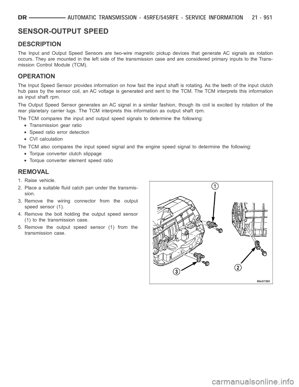
3. Remove the wiring connector from the output
speed sensor (1).
4. Remove the bolt holding the output speed sensor
(1) to the transmission case.
5. Remove the output speed sensor (1) from the
transmission case.
Page 3482 of 5267
CONVERTER-TORQUE
DESCRIPTION
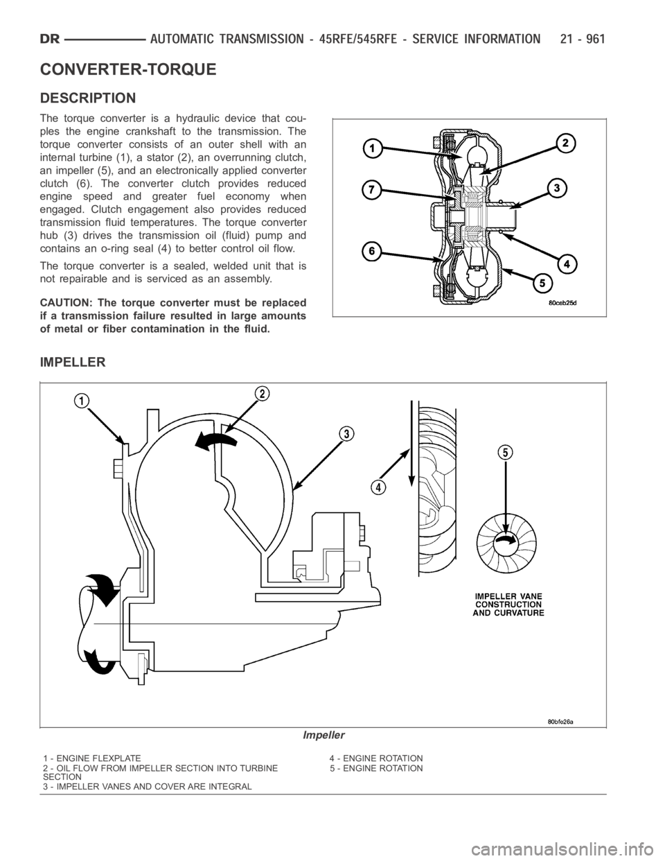
The torque converter is a hydraulic device that cou-
ples the engine crankshaft to the transmission. The
torque converter consists of an outer shell with an
internal turbine (1), a stator (2), an overrunning clutch,
an impeller (5), and an electronically applied converter
clutch (6). The converterclutch provides reduced
engine speed and greater fuel economy when
engaged. Clutch engagement also provides reduced
transmission fluid temperatures. The torque converter
hub (3) drives the transmission oil (fluid) pump and
contains an o-ring seal (4) to better control oil flow.
The torque converter is a sealed, welded unit that is
not repairable and is serviced as an assembly.
CAUTION: The torque converter must be replaced
if a transmission failure resulted in large amounts
of metal or fiber contamination in the fluid.
IMPELLER
Impeller
1 - ENGINE FLEXPLATE 4 - ENGINE ROTATION
2 - OIL FLOW FROM IMPELLER SECTION INTO TURBINE
SECTION5 - ENGINE ROTATION
3 - IMPELLER VANES AND COVER ARE INTEGRAL
Page 3483 of 5267
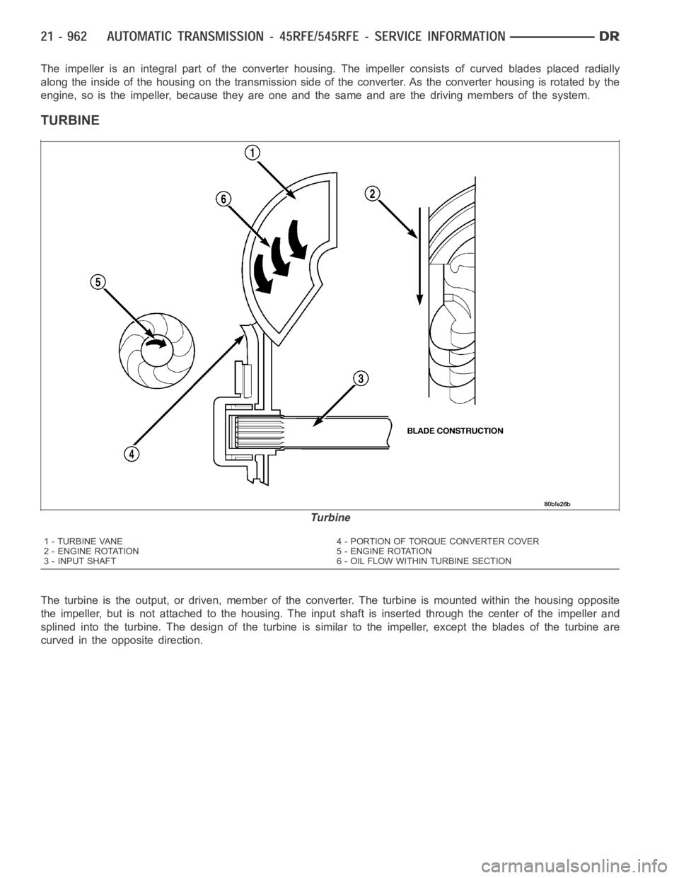
The impeller is an integral part of the converter housing. The impeller consists of curved blades placed radially
along the inside of the housing on the transmission side of the converter. As the converter housing is rotated by the
engine, so is the impeller, because they are one and the same and are the driving members of the system.
TURBINE
The turbine is the output, or driven, member of the converter. The turbine is mounted within the housing opposite
the impeller, but is not attached to the housing. The input shaft is inserted through the center of the impeller and
splined into the turbine. The design of the turbine is similar to the impeller, except the blades of the turbine are
curved in the opposite direction.
Turbine
1 - TURBINE VANE 4 - PORTION OF TORQUE CONVERTER COVER
2 - ENGINE ROTATION 5 - ENGINE ROTATION
3 - INPUT SHAFT 6 - OIL FLOW WITHIN TURBINE SECTION
Page 3485 of 5267
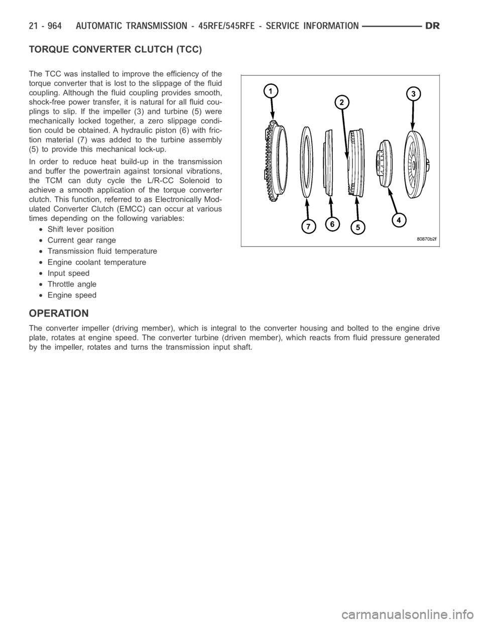
TORQUE CONVERTER CLUTCH (TCC)
The TCC was installed to improve the efficiency of the
torque converter that is lost to the slippage of the fluid
coupling. Although the fluid coupling provides smooth,
shock-free power transfer, it is natural for all fluid cou-
plings to slip. If the impeller (3) and turbine (5) were
mechanically locked together, a zero slippage condi-
tion could be obtained. A hydraulic piston (6) with fric-
tion material (7) was added to the turbine assembly
(5) to provide this mechanical lock-up.
In order to reduce heat build-up in the transmission
and buffer the powertrain against torsional vibrations,
the TCM can duty cycle the L/R-CC Solenoid to
achieve a smooth application of the torque converter
clutch. This function, referred to as Electronically Mod-
ulated Converter Clutch (EMCC) can occur at various
times depending on the following variables:
Shift lever position
Current gear range
Transmission fluid temperature
Engine coolant temperature
Input speed
Throttle angle
Engine speed
OPERATION
The converter impeller (driving member), which is integral to the converter housing and bolted to the engine drive
plate, rotates at engine speed. The converter turbine (driven member), which reacts from fluid pressure generated
by the impeller, rotates and turns the transmission input shaft.
Page 3487 of 5267
TORQUE CONVERTER CLUTCH (TCC)
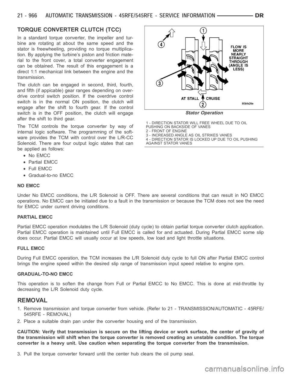
In a standard torque converter, the impeller and tur-
bine are rotating at about the same speed and the
stator is freewheeling, providing no torque multiplica-
tion. By applying the turbine’s piston and friction mate-
rial to the front cover, a total converter engagement
can be obtained. The result of this engagement is a
direct 1:1 mechanical link between the engine and the
transmission.
The clutch can be engaged in second, third, fourth,
and fifth (if appicable) gear ranges depending on over-
drive control switch position. If the overdrive control
switch is in the normal ON position, the clutch will
engage after the shift to fourth gear. If the control
switch is in the OFF position, the clutch will engage
after the shift to third gear.
The TCM controls the torque converter by way of
internal logic software. The programming of the soft-
ware provides the TCM with control over the L/R-CC
Solenoid. There are four output logic states that can
be applied as follows:
No EMCC
Partial EMCC
Full EMCC
Gradual-to-no EMCC
NO EMCC
Under No EMCC conditions, the L/R Solenoid is OFF. There are several conditions that can result in NO EMCC
operations. No EMCC can be initiated due to a fault in the transmission or because the TCM does not see the need
for EMCC under current driving conditions.
PARTIAL EMCC
Partial EMCC operation modulates the L/R Solenoid (duty cycle) to obtain partial torque converter clutch application.
Partial EMCC operation is maintaineduntil Full EMCC is called for and actuated. During Partial EMCC some slip
does occur. Partial EMCC will usually occur at low speeds, low load and light throttle situations.
FULL EMCC
During Full EMCC operation, the TCM increases the L/R Solenoid duty cycle to full ON after Partial EMCC control
brings the engine speed within the desired slip range of transmission input speed relative to engine rpm.
GRADUAL-TO-NO EMCC
This operation is to soften the change from Full or Partial EMCC to No EMCC. This is done at mid-throttle by
decreasing the L/R Solenoid duty cycle.
REMOVAL
1. Remove transmission and torque converter from vehicle. (Refer to 21 - TRANSMISSION/AUTOMATIC - 45RFE/
545RFE - REMOVAL)
2. Place a suitable drain pan under the converter housing end of the transmission.
CAUTION: Verify that transmission is secure on the lifting device or work surface, the center of gravity of
the transmission will shift when the torque converter is removed creatingan unstable condition. The torque
converter is a heavy unit. Use caution when separating the torque converter from the transmission.
3. Pull the torque converter forward until the center hub clears the oil pumpseal.
Stator Operation
1 - DIRECTION STATOR WILL FREE WHEEL DUE TO OIL
PUSHING ON BACKSIDE OF VANES
2-FRONTOFENGINE
3 - INCREASED ANGLE AS OIL STRIKES VANES
4 - DIRECTION STATOR IS LOCKED UP DUE TO OIL PUSHING
AGAINST STATOR VANES
Page 3494 of 5267
SENSOR-TRANSMISSION TEMPERATURE
DESCRIPTION
The transmission temperature sensor is a thermistor that is integral to the Transmission Range Sensor (TRS).
OPERATION
The transmission temperature sensor is used by the TCM to sense the temperature of the fluid in the sump. Since
fluid temperature can affect transmission shift quality and convertor lock up, the TCM requires this information to
determine which shift schedule to operate in.
Calculated Temperature
A failure in the temperature sensor or circuit will result in calculated temperature being substituted for actual tem-
perature. Calculated temperature is a predicted fluid temperature whichis calculated from a combination of inputs:
Battery (ambient) temperature
Engine coolant temperature
In-gear run time since start-up
Page 3511 of 5267
Theory of Operation
The Transmission Temperature Sensor is used to sense when the transmissiontemperatureistoohotortoocoldto
operate overdrive and/or the torque convertor clutch. When the transmission sensor detects a temperature below 0°
C (32° F), overdrive and the torque convertor clutch are disabled. When thedetected temperature is above 127° C
(260° F), overdrive is disabled and 3rd gear with TCC is engaged, this strategy is used to increase transmission
fluid flow to help cool the transmission.
When Monitored:
Continuously with the ignition on and the engine running.
Set Condition:
The DTC will set after two consecutive trips in which the transmission oil temperature is greater than 5° C (40°
F) and the transmission oil temperature does not rise more than 8° C (16° F) after 20 minutes of run time with
a vehicle speed greater than 48 Kmh (30 mph). The DTC will also set if the engine temperature is greater than
38° C (100° F) with the transmission oil temperature greater than 127° C (260° F).
Possible Causes
OTHER TRANSMISSION DTC’S SET
INTERMITTENT TRANSMISSION TEMPERATURE SENSOR
TRANSMISSION TEMPERATURE SENSOR
Always perform the Pre-Diagnostic Troubleshooting procedure before proceeding. (Refer to 21 - TRANSMIS-
SION/TRANSAXLE/AUTOMATIC - 48RE - STANDARD PROCEDURE)
Diagnostic Test
1.CHECK IF THE DTC IS CURRENT
Ignition on, engine not running.
With the scan tool, read Engine DTCs.
Record the Freeze Frame data for the reported DTC.
With the scan tool, erase DTCs.
Turn the ignition off to the lock position.
Using the Freeze Frame data recorded earlier, try to duplicate the conditions in which the DTC originally set.
NOTE: It may be necessary to road test the vehicle to duplicate the originalset conditions.
With the scan tool, read Engine DTCs.
Did the DTC reset?
Ye s>>
Go To 2
No>>
Go To 6
2.CHECK FOR OTHER TRANSMISSION DTCS
Does the scan tool show any Park/Neutral DTCs?
Ye s>>
Refer to the Transmission category and perform the appropriate symptom(s).
No>>
Go To 3