2006 DODGE RAM SRT-10 check oil
[x] Cancel search: check oilPage 2087 of 5267
INSPECTION FOR REAR SEAL AREA LEAKS
Since it is sometimes difficult to determine the source of an oil leak in therear seal area of the engine, a more
involved inspection is necessary. The following steps should be followedto help pinpoint the source of the leak.
If the leakage occurs at the crankshaft rear oil seal area:
1. Disconnect the battery.
2. Raise the vehicle.
3. Remove torque converter or clutch housing cover and inspect rear of block for evidence of oil. Use a black light
to check for the oil leak:
a. Circular spray pattern generally indicates seal leakage or crankshaftdamage.
b. Where leakage tends to run straight down, possible causes are a porous block, distributor seal, camshaft
bore cup plugs oil galley pipe plugs, oil filter runoff, and main bearing cap to cylinder block mating surfaces.
4. If no leaks are detected, pressurize the crankcase as outlined in the, Inspection (Engine oil Leaks in general)
CAUTION: Do not exceed 20.6 kPa (3 psi).
5. If the leak is not detected, very slowly turn the crankshaft and watch forleakage. If a leak is detected between
the crankshaft and seal while slowly turning the crankshaft, it is possible the crankshaft seal surface is damaged.
The seal area on the crankshaft could have minor nicks or scratches that canbe polished out with emery cloth.
CAUTION: Use extreme caution when crankshaft polishing is necessary to remove minor nicks and
scratches. The crankshaft seal flange is especially machined to complement the function of the rear oil seal.
6. For bubbles that remain steady with shaft rotation, no further inspection can be done until disassembled.
Page 2088 of 5267
OIL
STANDARD PROCEDURE
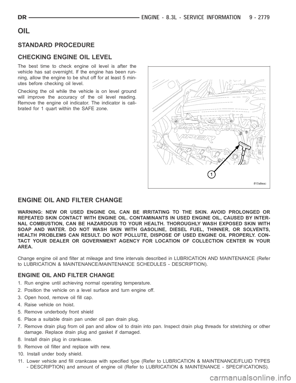
CHECKING ENGINE OIL LEVEL
The best time to check engine oil level is after the
vehicle has sat overnight. If the engine has been run-
ning, allow the engine to be shut off for at least 5 min-
utes before checking oil level.
Checking the oil while the vehicle is on level ground
will improve the accuracy of the oil level reading.
Remove the engine oil indicator. The indicator is cali-
brated for 1 quart within the SAFE zone.
ENGINE OIL AND FILTER CHANGE
WARNING: NEW OR USED ENGINE OIL CAN BE IRRITATING TO THE SKIN. AVOID PROLONGED OR
REPEATED SKIN CONTACT WITH ENGINE OIL. CONTAMINANTS IN USED ENGINE OIL, CAUSED BY INTER-
NAL COMBUSTION, CAN BE HAZARDOUS TO YOUR HEALTH. THOROUGHLY WASH EXPOSED SKIN WITH
SOAP AND WATER. DO NOT WASH SKIN WITH GASOLINE, DIESEL FUEL, THINNER, OR SOLVENTS,
HEALTH PROBLEMS CAN RESULT. DO NOT POLLUTE, DISPOSE OF USED ENGINE OIL PROPERLY. CON-
TACT YOUR DEALER OR GOVERNMENT AGENCY FOR LOCATION OF COLLECTION CENTER INYOUR
AREA.
Change engine oil and filter at mileage and time intervals described in LUBRICATION AND MAINTENANCE (Refer
to LUBRICATION & MAINTENANCE/MAINTENANCE SCHEDULES - DESCRIPTION).
ENGINE OIL AND FILTER CHANGE
1. Run engine until achieving normal operating temperature.
2. Position the vehicle on a level surface and turn engine off.
3. Open hood, remove oil fill cap.
4. Raise vehicle on hoist.
5. Remove underbody front shield
6. Place a suitable drain pan under oil pan drain plug.
7. Remove drain plug from oil pan and allow oil to drain into pan. Inspect drain plug threads for stretching or other
damage. Replace drain plug and gasket if damaged.
8. Install drain plug in crankcase.
9. Remove oil filter and replace with new.
10. Install under body shield.
11. Lower vehicle and fill crankcase with specified type (Refer to LUBRICATION & MAINTENANCE/FLUID TYPES
- DESCRIPTION) and amount of engine oil (Refer to LUBRICATION & MAINTENANCE - SPECIFICATIONS).
Page 2092 of 5267
INSTALLATION
1. Position oil cooler to mounting position.
2. Install oil cooler fasteners. Tighten to 12 Nꞏm (105
in. lbs.).
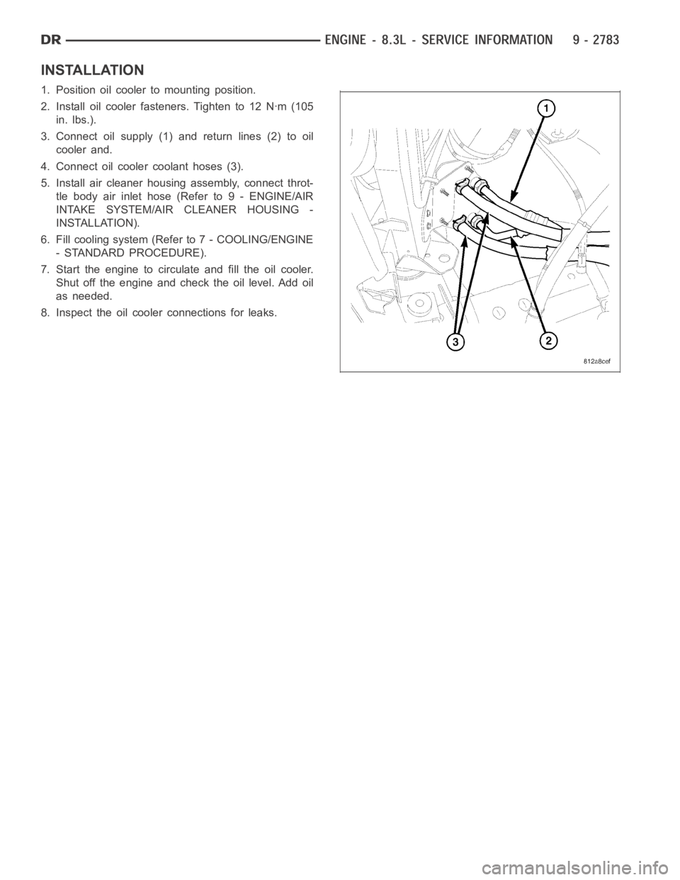
3. Connect oil supply (1) and return lines (2) to oil
cooler and.
4. Connect oil cooler coolant hoses (3).
5. Install air cleaner housing assembly, connect throt-
tle body air inlet hose (Refer to 9 - ENGINE/AIR
INTAKE SYSTEM/AIR CLEANER HOUSING -
INSTALLATION).
6. Fill cooling system (Refer to 7 - COOLING/ENGINE
- STANDARD PROCEDURE).
7. Start the engine to circulate and fill the oil cooler.
Shut off the engine and check the oil level. Add oil
as needed.
8. Inspect the oil cooler connections for leaks.
Page 2104 of 5267
BLOCK-ENGINE
DESCRIPTION
The cylinder block is made of a sand-cast aluminum alloy. The cylinder block has interference-fit cast iron cylinder
liners. The cylinder liners are thermally installed during block manufacturing; they are not serviceable items.
Six iron main bearing caps use four bolts per cap; two vertical and two horizontal. A crankshaft oil scraper is
attached to the main bearing caps via extended main bearing cap bolts and nuts.
STANDARD PROCEDURE - CYLINDER BORE HONING
Before honing, stuff plenty of clean shop towels under
the bores and over the crankshaft to keep abrasive
materials from entering the crankshaft area.
1. Used carefully, the Cylinder Bore Sizing Hone
C-823, equipped with 220 grit stones, is the best
tool for this job. In addition to deglazing, it will
reduce taper and out-of-round, as well as removing
light scuffing, scoring and scratches. Usually, a few
strokes will clean up a bore and maintain the
required limits.
CAUTION: DO NOT use rigid type hones to remove
cylinder wall glaze.
2. Deglazing of the cylinder walls may be done if the
cylinder bore is straight and round. Use a cylinder
surfacing hone, Honing Tool C-3501, equipped with
280 grit stones (C-3501-3810). about 20-60
strokes, depending on the bore condition, will be
sufficient to provide a satisfactory surface. Using
honing oil C-3501-3880, or a light honing oil, avail-
able from major oil distributors.
CAUTION: DO NOT use engine or transmission oil, mineral spirits, or kerosene.
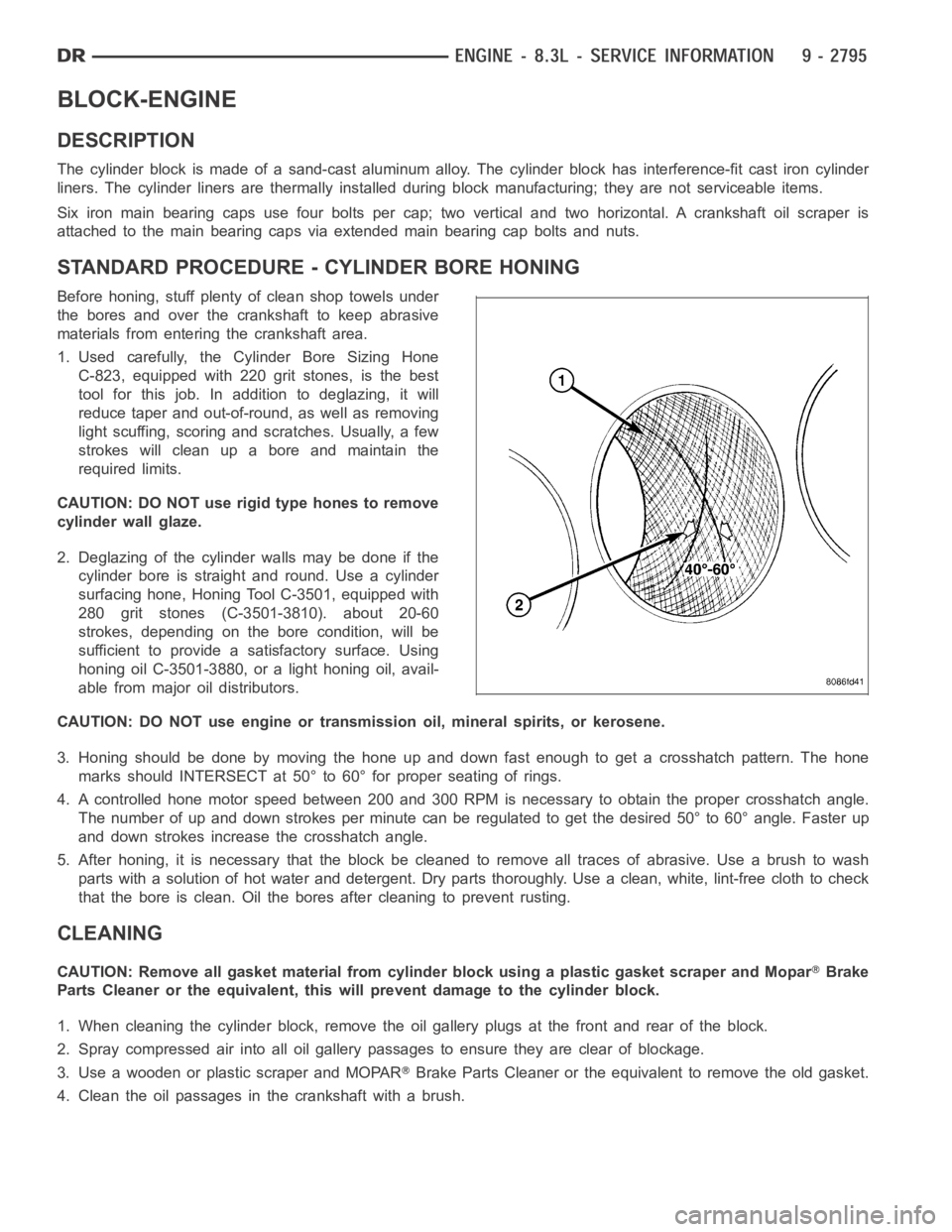
3. Honing should be done by moving the hone up and down fast enough to get a crosshatch pattern. The hone
marks should INTERSECT at 50° to 60° for proper seating of rings.
4. A controlled hone motor speed between 200 and 300 RPM is necessary to obtain the proper crosshatch angle.
The number of up and down strokes per minute can be regulated to get the desired 50° to 60° angle. Faster up
and down strokes increase the crosshatch angle.
5. After honing, it is necessary that the block be cleaned to remove all traces of abrasive. Use a brush to wash
parts with a solution of hot water and detergent. Dry parts thoroughly. Usea clean, white, lint-free cloth to check
that the bore is clean. Oil the bores after cleaning to prevent rusting.
CLEANING
CAUTION: Remove all gasket material from cylinder block using a plastic gasket scraper and MoparBrake
Parts Cleaner or the equivalent, this will prevent damage to the cylinder block.
1. When cleaning the cylinder block, remove the oil gallery plugs at the front and rear of the block.
2. Spray compressed air into all oil gallery passages to ensure they are clear of blockage.
3. Use a wooden or plastic scraper and MOPAR
Brake Parts Cleaner or the equivalent to remove the old gasket.
4. Clean the oil passages in the crankshaft with a brush.
Page 2112 of 5267
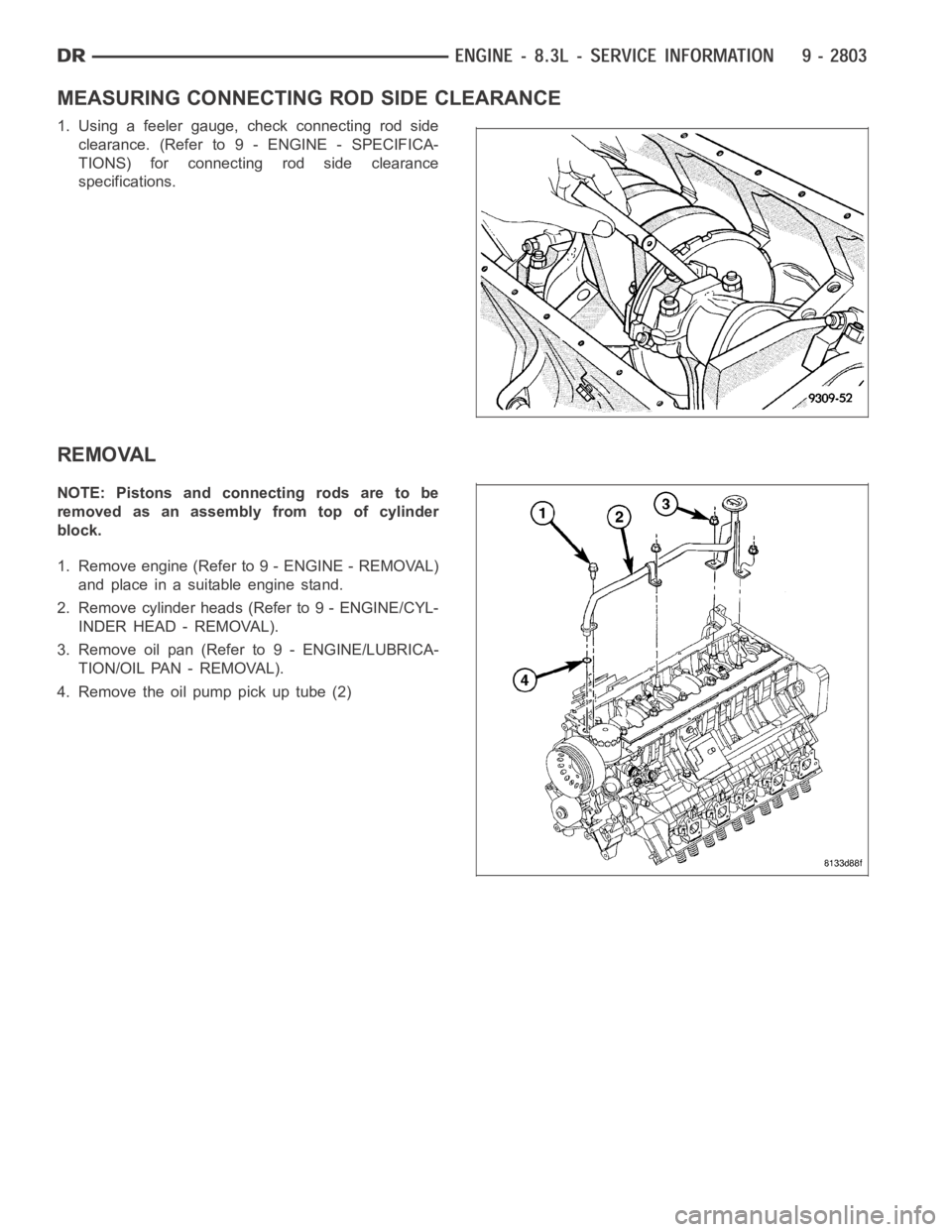
MEASURING CONNECTING ROD SIDE CLEARANCE
1. Using a feeler gauge, check connecting rod side
clearance. (Refer to 9 - ENGINE - SPECIFICA-
TIONS) for connecting rod side clearance
specifications.
REMOVAL
NOTE: Pistons and connecting rods are to be
removed as an assembly from top of cylinder
block.
1. Remove engine (Refer to 9 - ENGINE - REMOVAL)
and place in a suitable engine stand.
2. Remove cylinder heads (Refer to 9 - ENGINE/CYL-
INDER HEAD - REMOVAL).
3. Remove oil pan (Refer to 9 - ENGINE/LUBRICA-
TION/OIL PAN - REMOVAL).
4. Remove the oil pump pick up tube (2)
Page 2113 of 5267
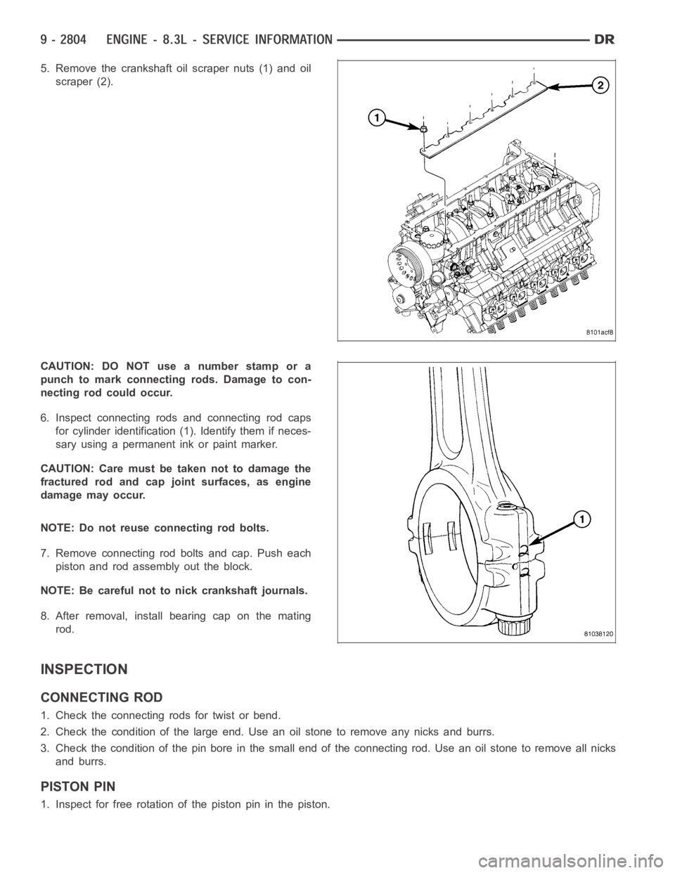
5. Remove the crankshaft oil scraper nuts (1) and oil
scraper (2).
CAUTION: DO NOT use a number stamp or a
punch to mark connecting rods. Damage to con-
necting rod could occur.
6. Inspect connecting rods and connecting rod caps
for cylinder identification (1). Identify them if neces-
sary using a permanent ink or paint marker.
CAUTION: Care must be taken not to damage the
fractured rod and cap joint surfaces, as engine
damage may occur.
NOTE: Do not reuse connecting rod bolts.
7. Remove connecting rod bolts and cap. Push each
piston and rod assembly out the block.
NOTE: Be careful not to nick crankshaft journals.
8. After removal, install bearing cap on the mating
rod.
INSPECTION
CONNECTING ROD
1. Check the connecting rods for twist or bend.
2. Check the condition of the large end. Use an oil stone to remove any nicks and burrs.
3. Check the condition of the pin bore in the small end of the connecting rod.Useanoilstonetoremoveallnicks
and burrs.
PISTON PIN
1. Inspect for free rotation of the piston pin in the piston.
Page 2116 of 5267
RINGS-PISTON
STANDARD PROCEDURE - MEASURING PISTON RING CLEARANCES
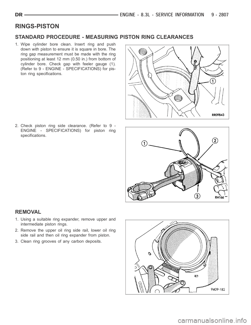
1. Wipe cylinder bore clean. Insert ring and push
down with piston to ensure it is square in bore. The
ring gap measurement must be made with the ring
positioning at least 12 mm (0.50 in.) from bottom of
cylinder bore. Check gap with feeler gauge (1).
(Refer to 9 - ENGINE - SPECIFICATIONS) for pis-
ton ring specifications.
2. Check piston ring side clearance. (Refer to 9 -
ENGINE - SPECIFICATIONS) for piston ring
specifications.
REMOVAL
1. Using a suitable ring expander, remove upper and
intermediate piston rings.
2. Remove the upper oil ring side rail, lower oil ring
side rail and then oil ring expander from piston.
3. Clean ring grooves of any carbon deposits.
Page 2119 of 5267
BEARINGS-CONNECTING ROD
DESCRIPTION
The bearing caps are not interchangeable and should be paint marked or scribed at removal to insure correct
assembly.
The bearing shells must be installed so that the tangs are in the machined grooves in the rods and caps.
Limits of taper or out-of-round on any crankshaft journals should be held to 0.013 mm (0.0005 in.). Bearings are
available in 0.025 mm (0.001 in.), 0.051 mm (0.002 in.), 0.076 mm (0.003 in.), 0.254 mm (0.010 in.) and 0.305 mm
(0.012 in.) undersize.Install the bearings in pairs. Do not use a new bearing half with an old bearing half. Do
not file the rods or bearing caps.
STANDARD PROCEDURE
CONNECTING ROD BEARING - FITTING
Fit all rods on one bank until complete. Do not alternate from one bank to another, because when the rods are
assembled to pistons correctly, they are not interchangeable from one bank to another.
The bearing caps are not interchangeable and should be marked at removal toinsure correct assembly.
The bearing shells must be installed so that the tangs are in the machined grooves in the rods and caps.
Limits of taper or out-of-round on any crankshaft journals should be held to 0.013 mm (0.0005 in.). Bearings are
available in 0.025 mm (0.001 in.), 0.051 mm (0.002 in.), 0.076 mm (0.003 in.), 0.254 mm (0.010 in.) and 0.305 mm
(0.012 in.) undersize.Install the bearings in pairs. Do not use a new bearing half with an old bearing half. Do
not file the rods or bearing caps.
1. (Refer to 9 - ENGINE/ENGINE BLOCK/CONNECTING ROD BEARINGS - STANDARD PROCEDURE) - Mea-
suring Connecting Rod Bearing Clearance to determine bearing clearance.
2. Before installing the connecting rod cap bolts, the bolt threads shouldbe oiled with engine oil.
3. Install bolts finger tight, then alternately torque each bolt to assemble the cap properly.
4. Tighten the connecting rod bolts to 68 Nꞏm (50 ft. lbs.).
MEASURING CONNECTING ROD BEARING CLEARANCE
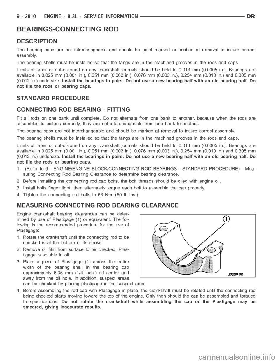
Engine crankshaft bearing clearances can be deter-
mined by use of Plastigage (1) or equivalent. The fol-
lowing is the recommended procedure for the use of
Plastigage:
1. Rotate the crankshaft until the connecting rod to be
checked is at the bottom of its stroke.
2. Remove oil film from surface to be checked. Plas-
tigage is soluble in oil.
3. Place a piece of Plastigage (1) across the entire
width of the bearing shell in the bearing cap
approximately 6.35 mm (1/4 inch.) off center and
away from the oil hole. In addition, suspect areas
can be checked by placing plastigage in the suspect area.
4. Before assembling the rod cap with Plastigage in place, the crankshaft must be rotated until the connecting rod
being checked starts moving toward the top of the engine. Only then should the cap be assembled and torqued
to specifications.Do not rotate the crankshaft while assembling the cap or the Plastigage maybe
smeared, giving inaccurate results.