2006 DODGE RAM SRT-10 check oil
[x] Cancel search: check oilPage 2126 of 5267
BEARINGS-CRANKSHAFT MAIN
DESCRIPTION
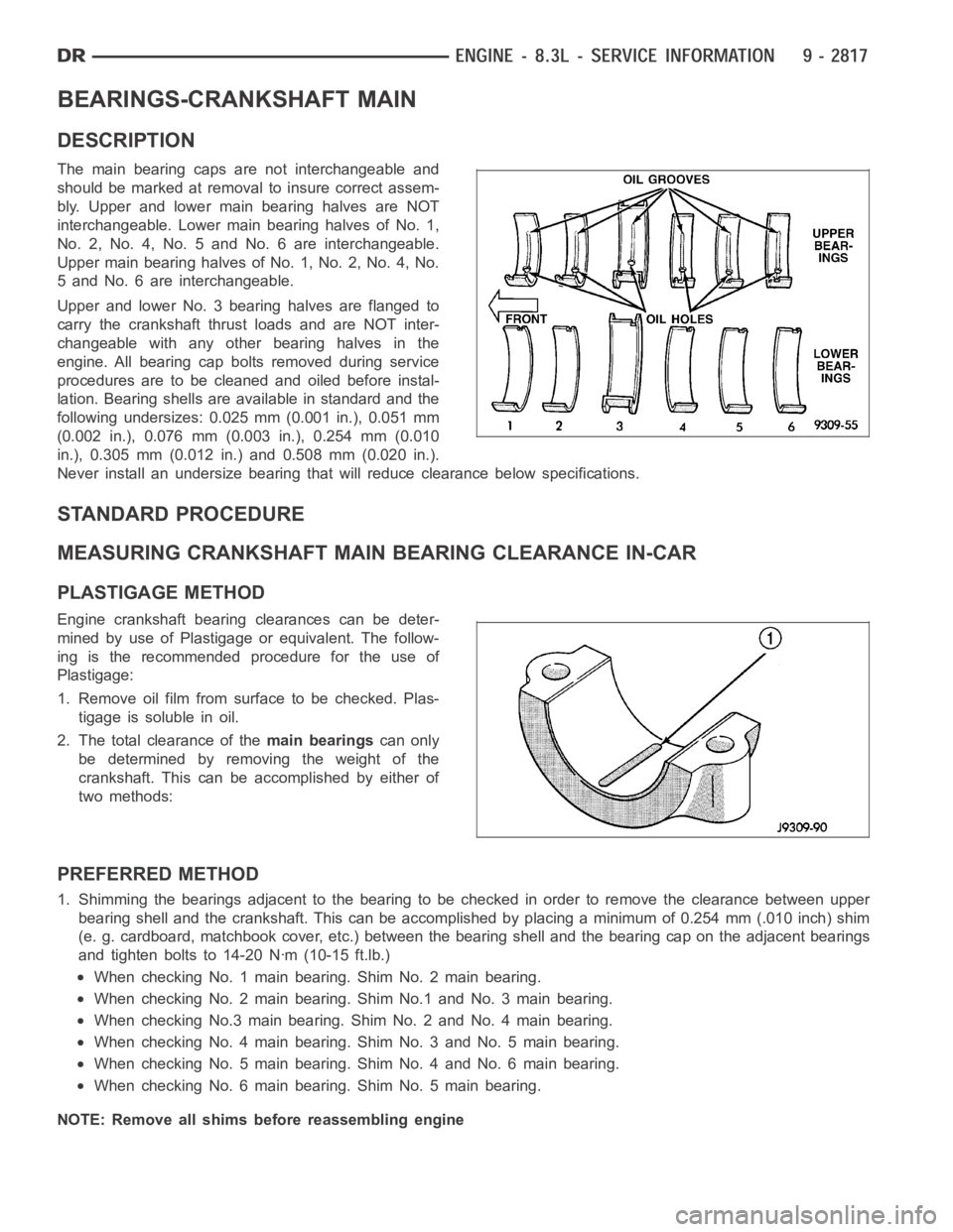
The main bearing caps are not interchangeable and
should be marked at removalto insure correct assem-
bly. Upper and lower main bearing halves are NOT
interchangeable. Lower main bearing halves of No. 1,
No. 2, No. 4, No. 5 and No. 6 are interchangeable.
Upper main bearing halves of No. 1, No. 2, No. 4, No.
5 and No. 6 are interchangeable.
Upper and lower No. 3 bearing halves are flanged to
carry the crankshaft thrust loads and are NOT inter-
changeable with any other bearing halves in the
engine. All bearing cap bolts removed during service
procedures are to be cleaned and oiled before instal-
lation. Bearing shells are available in standard and the
following undersizes: 0.025 mm (0.001 in.), 0.051 mm
(0.002 in.), 0.076 mm (0.003 in.), 0.254 mm (0.010
in.), 0.305 mm (0.012 in.) and 0.508 mm (0.020 in.).
Never install an undersize bearing that will reduce clearance below specifications.
STANDARD PROCEDURE
MEASURING CRANKSHAFT MAIN BEARING CLEARANCE IN-CAR
PLASTIGAGE METHOD
Engine crankshaft bearing clearances can be deter-
mined by use of Plastigage or equivalent. The follow-
ing is the recommended procedure for the use of
Plastigage:
1. Remove oil film from surface to be checked. Plas-
tigage is soluble in oil.
2. The total clearance of themain bearingscan only
be determined by removing the weight of the
crankshaft. This can be accomplished by either of
two methods:
PREFERRED METHOD
1. Shimming the bearings adjacent to the bearing to be checked in order to remove the clearance between upper
bearing shell and the crankshaft. Thiscanbeaccomplishedbyplacingaminimum of 0.254 mm (.010 inch) shim
(e. g. cardboard, matchbook cover, etc.) between the bearing shell and thebearing cap on the adjacent bearings
and tighten bolts to 14-20 Nꞏm (10-15 ft.lb.)
When checking No. 1 main bearing. Shim No. 2 main bearing.
When checking No. 2 main bearing. Shim No.1 and No. 3 main bearing.
When checking No.3 main bearing. Shim No. 2 and No. 4 main bearing.
When checking No. 4 main bearing. Shim No. 3 and No. 5 main bearing.
When checking No. 5 main bearing. Shim No. 4 and No. 6 main bearing.
When checking No. 6 main bearing. Shim No. 5 main bearing.
NOTE: Remove all shims before reassembling engine
Page 2127 of 5267
ALTERNATIVE METHOD
1. With the weight of the crankshaft being supported
by a jack under the counterweight adjacent to the
bearing being checked.
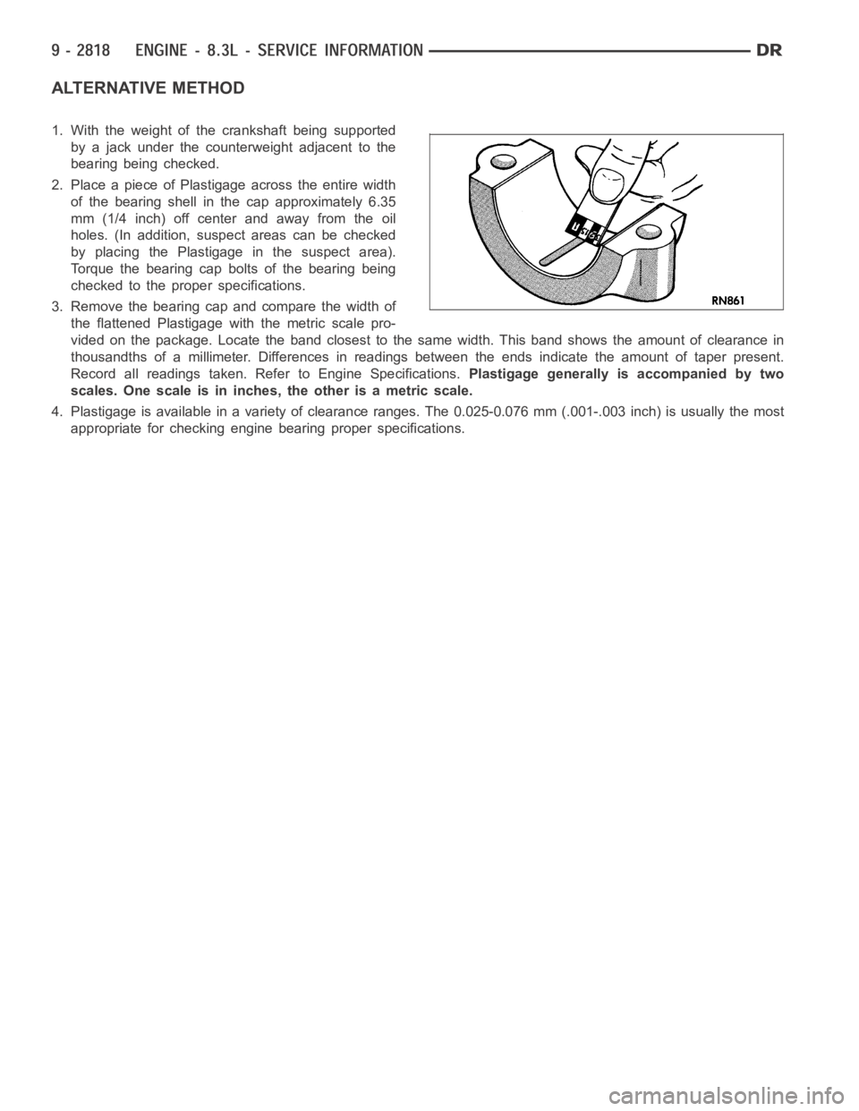
2. Place a piece of Plastigage across the entire width
of the bearing shell in the cap approximately 6.35
mm (1/4 inch) off center and away from the oil
holes. (In addition, suspect areas can be checked
by placing the Plastigage in the suspect area).
Torque the bearing cap bolts of the bearing being
checked to the proper specifications.
3. Remove the bearing cap and compare the width of
the flattened Plastigage with the metric scale pro-
vided on the package. Locate the band closest to the same width. This band shows the amount of clearance in
thousandths of a millimeter. Differences in readings between the ends indicate the amount of taper present.
Record all readings taken. Refer to Engine Specifications.Plastigage generally is accompanied by two
scales. One scale is in inches, the other is a metric scale.
4. Plastigage is available in a variety of clearance ranges. The 0.025-0.076 mm (.001-.003 inch) is usually the most
appropriate for checking engine bearing proper specifications.
Page 2128 of 5267
CRANKSHAFT
STANDARD PROCEDURE
MEASURING CRANKSHAFT END PLAY
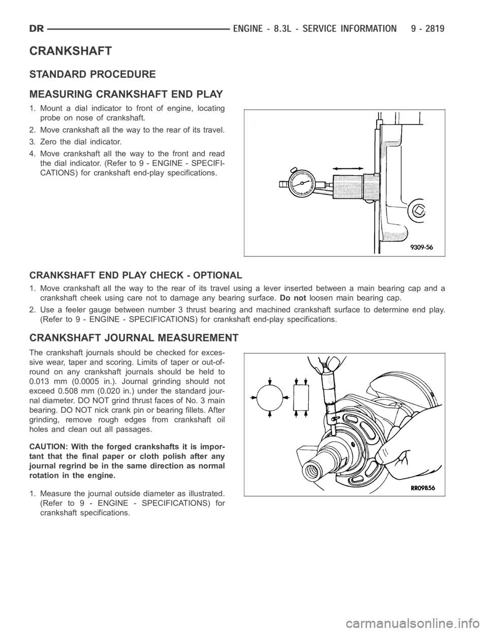
1. Mount a dial indicator to front of engine, locating
probe on nose of crankshaft.
2. Move crankshaft all the way to the rear of its travel.
3. Zero the dial indicator.
4. Move crankshaft all the way to the front and read
the dial indicator. (Referto 9 - ENGINE - SPECIFI-
CATIONS) for crankshaft end-play specifications.
CRANKSHAFT END PLAY CHECK - OPTIONAL
1. Move crankshaft all the way to the rear of its travel using a lever inserted between a main bearing cap and a
crankshaft cheek using care not to damage any bearing surface.Do notloosen main bearing cap.
2. Use a feeler gauge between number 3 thrust bearing and machined crankshaft surface to determine end play.
(Refer to 9 - ENGINE - SPECIFICATIONS) for crankshaft end-play specifications.
CRANKSHAFT JOURNAL MEASUREMENT
The crankshaft journals should be checked for exces-
sive wear, taper and scoring. Limits of taper or out-of-
round on any crankshaft journals should be held to
0.013 mm (0.0005 in.). Journal grinding should not
exceed 0.508 mm (0.020 in.) under the standard jour-
nal diameter. DO NOT grind thrust faces of No. 3 main
bearing. DO NOT nick crank pin or bearing fillets. After
grinding, remove rough edges from crankshaft oil
holes and clean out all passages.
CAUTION: With the forged crankshafts it is impor-
tant that the final paper or cloth polish after any
journal regrind be in the same direction as normal
rotation in the engine.
1. Measure the journal outside diameter as illustrated.
(Refer to 9 - ENGINE - SPECIFICATIONS) for
crankshaft specifications.
Page 2131 of 5267
INSPECTION
1. The crankshaft journals should be checked for excessive wear, taper andscoring. Limits of taper or out-of-round
on any crankshaft journals should be held to 0.025 mm (0.001 in.). Journal grinding should not exceed 0.508 mm
(0.020 inch) under the standard journal diameter. DO NOT grind thrust faces of No. 3 main bearing. DO NOT
nick crank pin or bearing fillets. After grinding, remove rough edges fromcrankshaft oil holes and clean out all
passages.
CAUTION: With the forged crankshafts it is important that the final paper or cloth polish after any journal
regrind be in the same direction as normal rotation in the engine.
2. Check and clean all oil holes for blockage and debris.
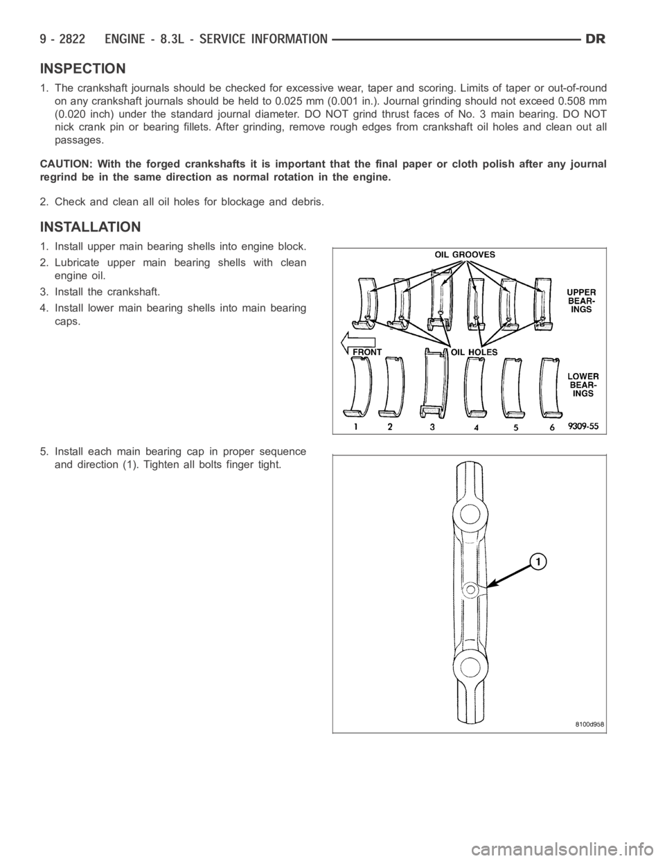
INSTALLATION
1. Install upper main bearing shells into engine block.
2. Lubricate upper main bearing shells with clean
engine oil.
3. Install the crankshaft.
4. Install lower main bearing shells into main bearing
caps.
5. Install each main bearing cap in proper sequence
and direction (1). Tighten all bolts finger tight.
Page 2145 of 5267
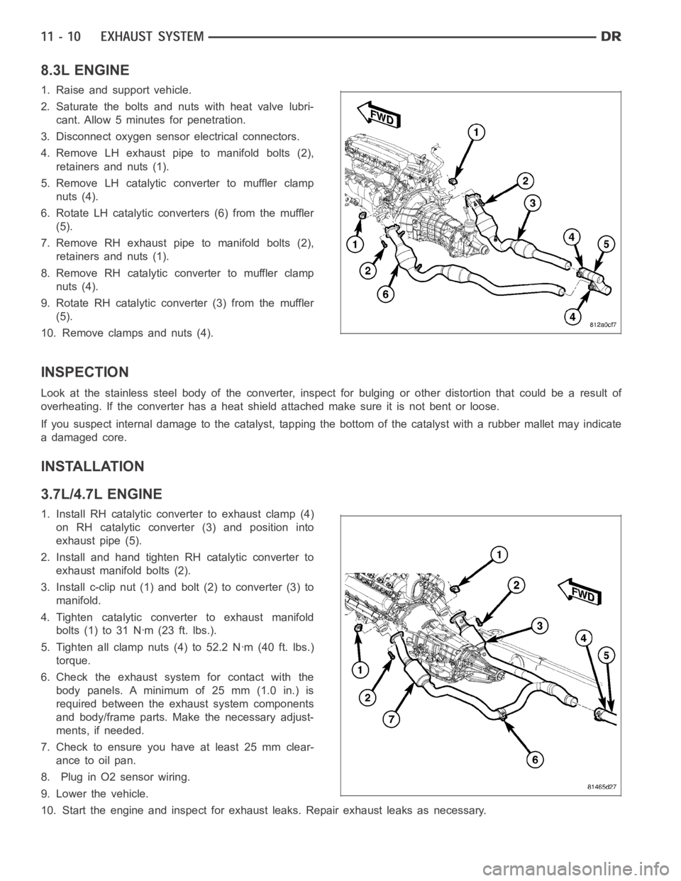
8.3L ENGINE
1. Raise and support vehicle.
2. Saturate the bolts and nuts with heat valve lubri-
cant. Allow 5 minutes for penetration.
3. Disconnect oxygen sensor electrical connectors.
4. Remove LH exhaust pipe to manifold bolts (2),
retainers and nuts (1).
5. Remove LH catalytic converter to muffler clamp
nuts (4).
6. Rotate LH catalytic converters (6) from the muffler
(5).
7. Remove RH exhaust pipe to manifold bolts (2),
retainers and nuts (1).
8. Remove RH catalytic converter to muffler clamp
nuts (4).
9. Rotate RH catalytic converter (3) from the muffler
(5).
10. Remove clamps and nuts (4).
INSPECTION
Look at the stainless steel body of the converter, inspect for bulging or other distortion that could be a result of
overheating. If the converter has a heat shield attached make sure it is notbent or loose.
If you suspect internal damage to the catalyst, tapping the bottom of the catalyst with a rubber mallet may indicate
a damaged core.
INSTALLATION
3.7L/4.7L ENGINE
1. Install RH catalytic converter to exhaust clamp (4)
on RH catalytic converter (3) and position into
exhaust pipe (5).
2. Install and hand tighten RH catalytic converter to
exhaust manifold bolts (2).
3. Install c-clip nut (1) and bolt (2) to converter (3) to
manifold.
4. Tighten catalytic converter to exhaust manifold
bolts(1)to31Nꞏm(23ft.lbs.).
5. Tighten all clamp nuts (4) to 52.2 Nꞏm (40 ft. lbs.)
torque.
6. Check the exhaust system for contact with the
body panels. A minimum of 25 mm (1.0 in.) is
required between the exhaust system components
and body/frame parts. Make the necessary adjust-
ments, if needed.
7. Check to ensure you have at least 25 mm clear-
ance to oil pan.
8. Plug in O2 sensor wiring.
9. Lower the vehicle.
10. Start the engine and inspect for exhaust leaks. Repair exhaust leaks asnecessary.
Page 2160 of 5267
TURBOCHARGER SYSTEM
DIAGNOSIS AND TESTING
TURBOCHARGER BOOST PRESSURE
Low turbocharger boost pressure can cause poor engine performance and driveability concerns. The following pro-
cedure will test the turbocharger boost pressure.
Causes of low boost pressure include the following:
Restricted air inlet system
Leak in charge air cooler system
Restricted/high pressure drop across charge air cooler
Damaged turbocharger compressor wheel housing
Turbocharger wastegate stuck open
Excessive exhaust restriction
Causes of excessively high boost pressure include:
Turbocharger wastegate stuck closed
Turbocharger wastegate signal line leaking or damaged
Damaged wastegate command valve O-rings
Wastegate command valve mechanically stuck in actuated position
Several Diagnostic Trouble Codes (DTCs) can be set that will indicate highor low system boost levels. There is a
DTC for circuit faults relating to the electronically controlled wastegate command valve.
(Refer to 11 - EXHAUST SYSTEM/TURBOCHARGER SYSTEM/CHARGE AIR COOLER AND PLUMBING - DIAG-
NOSIS AND TESTING) for diagnosing of low or high boost pressure due to leaks.
NOTE: If oil is present on either the inlet or exhaust side of the turbo charger, check the charge air cooler
for evidence of oil. Clean charge air cooler of any oil before starting the engine. Failure to do this can result
in severe engine damage.
Page 2165 of 5267
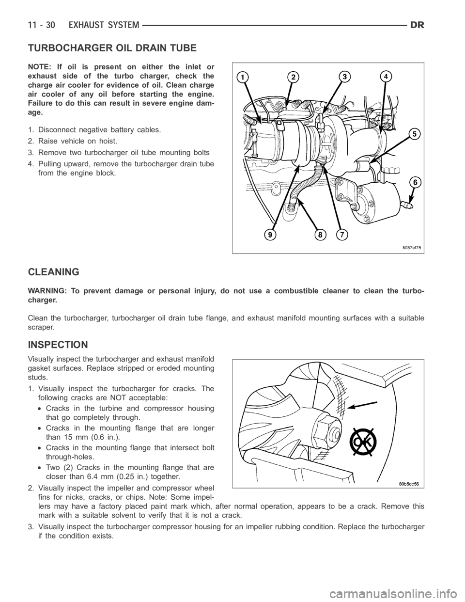
TURBOCHARGER OIL DRAIN TUBE
NOTE: If oil is present on either the inlet or
exhaust side of the turbo charger, check the
charge air cooler for evidence of oil. Clean charge
air cooler of any oil before starting the engine.
Failure to do this can result in severe engine dam-
age.
1. Disconnect negative battery cables.
2. Raise vehicle on hoist.
3. Remove two turbocharger oil tube mounting bolts
4. Pulling upward, remove the turbocharger drain tube
from the engine block.
CLEANING
WARNING: To prevent damage or personal injury, do not use a combustible cleaner to clean the turbo-
charger.
Clean the turbocharger, turbocharger oil drain tube flange, and exhaust manifold mounting surfaces with a suitable
scraper.
INSPECTION
Visually inspect the turbocharger and exhaust manifold
gasket surfaces. Replace stripped or eroded mounting
studs.
1. Visually inspect the turbocharger for cracks. The
following cracks are NOT acceptable:
Cracks in the turbine and compressor housing
that go completely through.
Cracks in the mounting flange that are longer
than 15 mm (0.6 in.).
Cracks in the mounting flange that intersect bolt
through-holes.
Two (2) Cracks in the mounting flange that are
closer than 6.4 mm (0.25 in.) together.
2. Visually inspect the impeller and compressor wheel
fins for nicks, cracks, or chips. Note: Some impel-
lers may have a factory placed paint mark which, after normal operation, appears to be a crack. Remove this
mark with a suitable solvent to verify that it is not a crack.
3. Visually inspect the turbocharger compressor housing for an impeller rubbing condition. Replace the turbocharger
if the condition exists.
Page 2167 of 5267
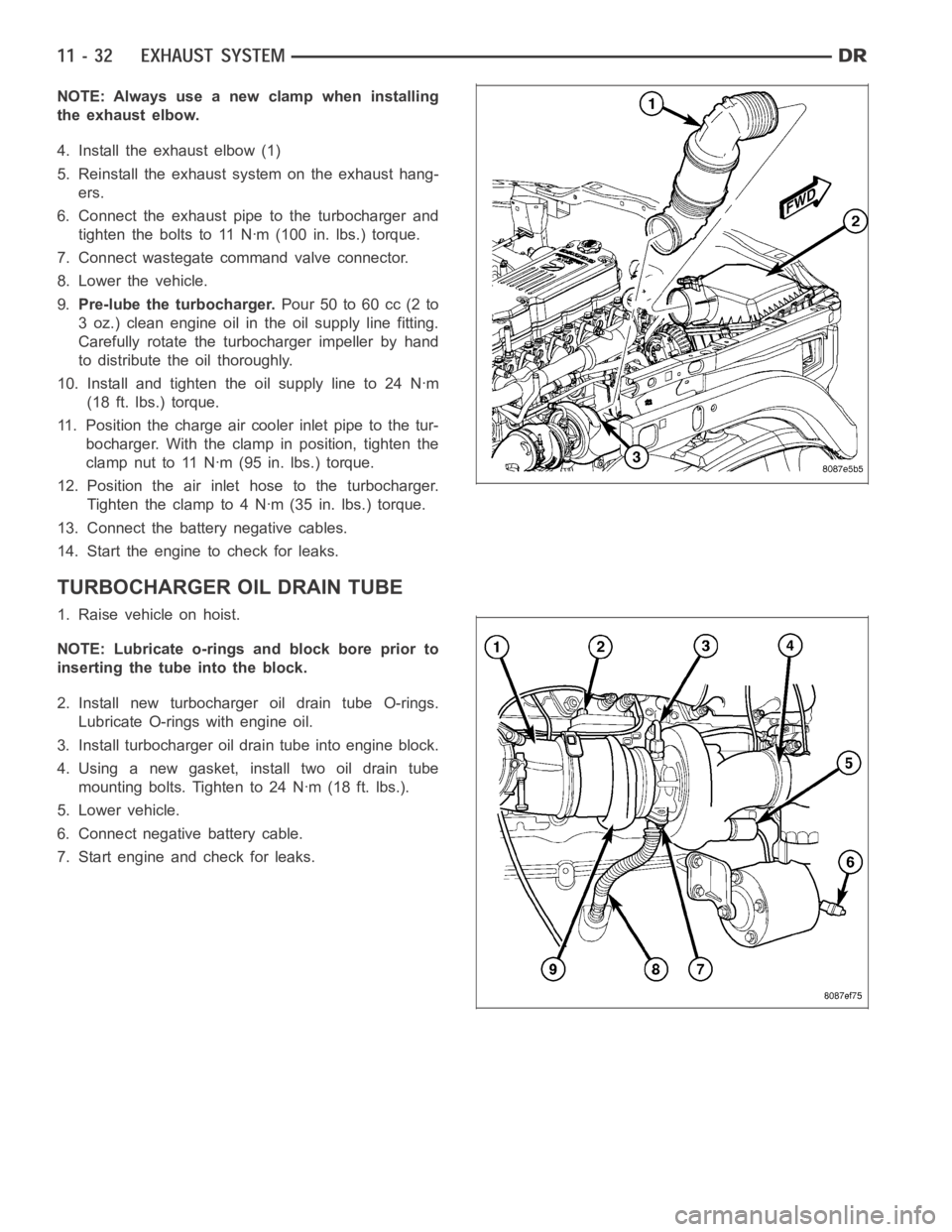
NOTE: Always use a new clamp when installing
the exhaust elbow.
4. Install the exhaust elbow (1)
5. Reinstall the exhaust system on the exhaust hang-
ers.
6. Connect the exhaust pipe to the turbocharger and
tighten the bolts to 11 Nꞏm (100 in. lbs.) torque.
7. Connect wastegate command valve connector.
8. Lower the vehicle.
9.Pre-lube the turbocharger.Pour 50 to 60 cc (2 to
3 oz.) clean engine oil in the oil supply line fitting.
Carefully rotate the turbocharger impeller by hand
to distribute the oil thoroughly.
10. Install and tighten the oil supply line to 24 Nꞏm
(18 ft. lbs.) torque.
11. Position the charge air cooler inlet pipe to the tur-
bocharger. With the clamp in position, tighten the
clamp nut to 11 Nꞏm (95 in. lbs.) torque.
12. Position the air inlet hose to the turbocharger.
Tighten the clamp to 4 Nꞏm (35 in. lbs.) torque.
13. Connect the battery negative cables.
14. Start the engine to check for leaks.
TURBOCHARGER OIL DRAIN TUBE
1. Raise vehicle on hoist.
NOTE: Lubricate o-rings and block bore prior to
inserting the tube into the block.
2. Install new turbocharger oil drain tube O-rings.
Lubricate O-rings with engine oil.
3. Install turbocharger oil drain tube into engine block.
4. Using a new gasket, install two oil drain tube
mounting bolts. Tighten to 24 Nꞏm (18 ft. lbs.).
5. Lower vehicle.
6. Connect negative battery cable.
7. Start engine and check for leaks.