Page 2133 of 5267
10. Install the crankshaft oil scraper and tighten nuts
to 23 Nꞏm (200 in. lbs.).
11.Installoilpumppickuptube(2)usinganew
o-ring (4). Torque 1/4-20 bolt to 11 Nꞏm (95 in.
lbs.). Torque 5/16-18 nuts to 23 Nꞏm (200 in. lbs.).
12. Install the crankshaft rear oil seal and retainer
(Refer to 9 - ENGINE/ENGINE BLOCK/CRANK-
SHAFT REAR OIL SEAL RETAINER - INSTALLA-
TION).
13. Install lower crankshaft gear along with the timing
chain (Refer to 9 - ENGINE/VALVE TIMING/TIM-
ING CHAIN AND SPROCKETS - INSTALLA-
TION).
14. Install timing chain cover (Refer to 9 - ENGINE/
VALVE TIMING/TIMING CHAIN COVER(S) -
INSTALLATION).
15. Install oil pan (Refer to 9 - ENGINE/LUBRICA-
TION/OIL PAN - INSTALLATION).
16. Install crankshaft damper and pulley (Refer to 9 -
ENGINE/ENGINE BLOCK/VIBRATION DAMPER -
INSTALLATION).
17. Install engine assembly (Refer to 9 - ENGINE -
INSTALLATION).
Page 2136 of 5267
EXHAUST SYSTEM
TABLE OF CONTENTS
page page
EXHAUST SYSTEM
DESCRIPTION
GAS ENGINES ............................... 2
5.9L DIESEL ................................. 3
DIAGNOSIS AND TESTING
GAS ENGINE ................................ 4
DIESEL ENGINE............................. 5
SPECIFICATIONS
TORQUE .................................... 5
SPECIAL TOOLS ............................... 7
CONVERTER-CATALYTIC
DESCRIPTION ................................. 8
OPERATION ................................... 8
REMOVAL
3.7L/4.7L ENGINE ............................ 8
5.7L ENGINE ................................ 9
5.9L DIESEL ENGINE ......................... 9
8.3L ENGINE ............................... 10
INSPECTION ................................. 10
INSTALLATION
3.7L/4.7L ENGINE ........................... 10
5.7L ENGINE ............................... 11
5.9L ENGINE DIESEL ........................ 11
8.3L ENGINE ............................... 12
PIPE EXHAUST
REMOVAL
3.7L/4.7L/5.7L ENGINE ...................... 13
5.9L DIESEL ................................ 13
8.3L ENGINE ............................... 13
INSPECTION ................................. 14
INSTALLATION
3.7L/4.7L/5.7L ENGINE ...................... 14
5.9L DIESEL ................................ 14
8.3L ENGINE ............................... 15
HEAT SHIELDS
DESCRIPTION ................................ 16
REMOVAL .................................... 16
INSTALLATION ............................... 17
MUFFLER
REMOVAL
3.7L/4.7L/5.7L ENGINE ...................... 19
8.3L ENGINE ............................... 195.9L DIESEL ENGINE....................... 20
INSTALLATION
3.7L/4.7L/5.7L ENGINE ...................... 20
8.3L ENGINE ............................... 21
5.9L DIESEL ENGINE....................... 21
TAILPIPE
REMOVAL
3.7L/4.7L/5.7L ENGINE ...................... 22
5.9L DIESEL................................ 22
8.3L ENGINE ............................... 23
INSPECTION ................................. 23
INSTALLATION
3.7L/4.7L/5.7L ENGINE ...................... 23
5.9L DIESEL................................ 24
8.3L ENGINE ............................... 24
TURBOCHARGER SYSTEM
DIAGNOSIS AND TESTING
TURBOCHARGER BOOST PRESSURE ....... 25
TURBOCHARGER
DESCRIPTION ................................ 26
OPERATION .................................. 27
REMOVAL
TURBOCHARGER .......................... 29
TURBOCHARGER OIL DRAIN TUBE .......... 30
CLEANING ................................... 30
INSPECTION ................................. 30
INSTALLATION
TURBOCHARGER .......................... 31
TURBOCHARGER OIL DRAIN TUBE .......... 32
WASTEGATE - ELECTRONIC ACTUATOR
REMOVAL .................................... 33
INSTALLATION ............................... 33
CHARGE AIR COOLER AND PLUMBING
DESCRIPTION ................................ 34
OPERATION .................................. 34
DIAGNOSIS AND TESTING
CHARGE AIR COOLER SYSTEM - LEAKS.... 35
REMOVAL .................................... 35
CLEANING ................................... 36
INSPECTION ................................. 36
INSTALLATION ............................... 36
Page 2137 of 5267
EXHAUST SYSTEM
DESCRIPTION
GAS ENGINES
CAUTION: Avoid application of rust prevention compounds or undercoatingmaterials to exhaust system
floor pan exhaust heat shields. Light overspray near the edges is permitted. Application of coating will
result in excessive floor pan temperatures and objectionable fumes.
The federal gasoline engine exhaust system consists of engine exhaust manifolds, exhaust pipes, catalytic convert-
er(s), extension pipe (if needed), exhaust heat shields, muffler and exhaust tailpipe ,.
The California emission vehicles exhaust system also contains the above components as well as mini catalytic con-
verters added to the exhaust pipe.
Page 2138 of 5267
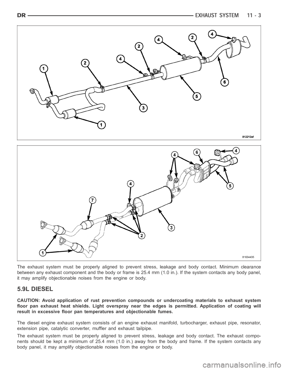
The exhaust system must be properly aligned to prevent stress, leakage andbody contact. Minimum clearance
between any exhaust component and the body or frame is 25.4 mm (1.0 in.). If the system contacts any body panel,
it may amplify objectionable noises from the engine or body.
5.9L DIESEL
CAUTION: Avoid application of rust prevention compounds or undercoatingmaterials to exhaust system
floor pan exhaust heat shields. Light overspray near the edges is permitted. Application of coating will
result in excessive floor pan temperatures and objectionable fumes.
The diesel engine exhaust system consists of an engine exhaust manifold, turbocharger, exhaust pipe, resonator,
extension pipe, catalytic converter, muffler and exhaust tailpipe.
The exhaust system must be properly aligned to prevent stress, leakage andbody contact. The exhaust compo-
nents should be kept a minimum of 25.4 mm (1.0 in.) away from the body and frame. If the system contacts any
body panel, it may amplify objectionable noises from the engine or body.
Page 2139 of 5267
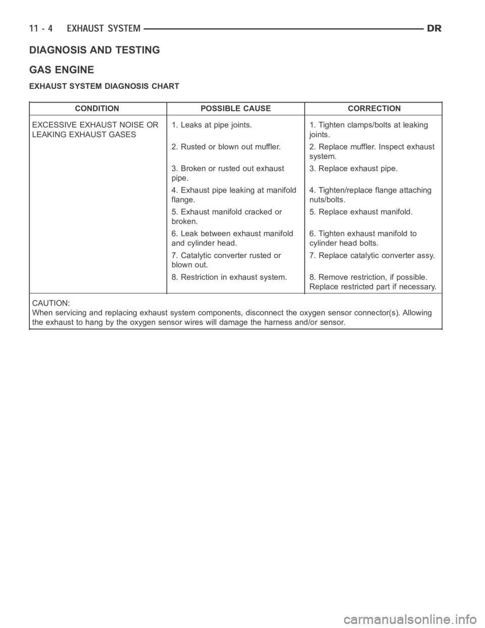
DIAGNOSIS AND TESTING
GAS ENGINE
EXHAUST SYSTEM DIAGNOSIS CHART
CONDITION POSSIBLE CAUSE CORRECTION
EXCESSIVE EXHAUST NOISE OR
LEAKING EXHAUST GASES1. Leaks at pipe joints. 1. Tighten clamps/bolts at leaking
joints.
2. Rusted or blown out muffler. 2. Replace muffler. Inspect exhaust
system.
3. Broken or rusted out exhaust
pipe.3. Replace exhaust pipe.
4. Exhaust pipe leaking at manifold
flange.4. Tighten/replace flange attaching
nuts/bolts.
5. Exhaust manifold cracked or
broken.5. Replace exhaust manifold.
6. Leak between exhaust manifold
and cylinder head.6. Tighten exhaust manifold to
cylinder head bolts.
7. Catalytic converter rusted or
blown out.7. Replace catalytic converter assy.
8. Restriction in exhaust system. 8. Remove restriction, if possible.
Replace restricted part if necessary.
CAUTION:
When servicing and replacing exhaust system components, disconnect the oxygen sensor connector(s). Allowing
the exhaust to hang by the oxygen sensor wires will damage the harness and/or sensor.
Page 2140 of 5267
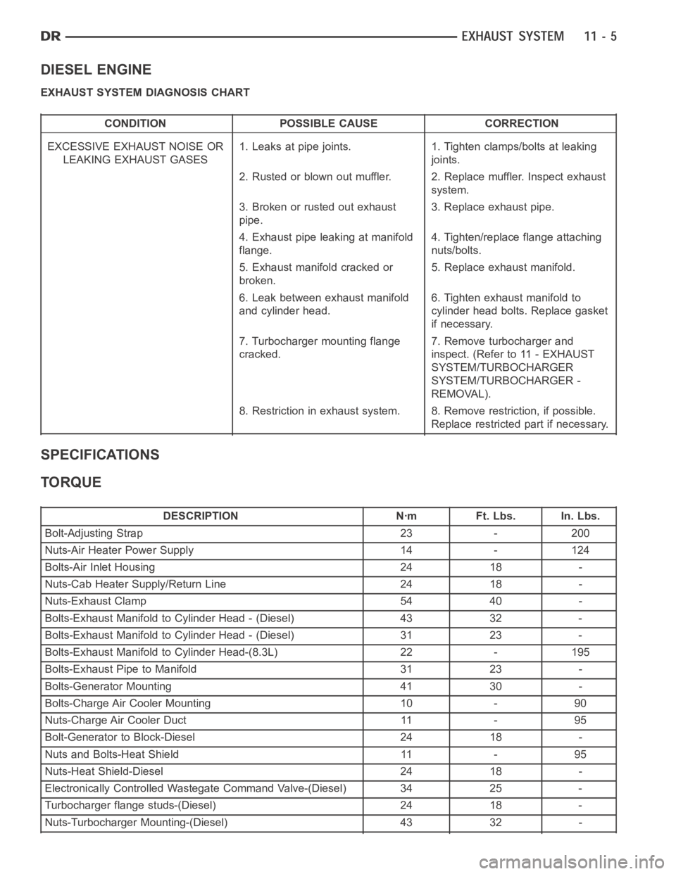
DIESEL ENGINE
EXHAUST SYSTEM DIAGNOSIS CHART
CONDITION POSSIBLE CAUSE CORRECTION
EXCESSIVE EXHAUST NOISE OR
LEAKING EXHAUST GASES1. Leaks at pipe joints. 1. Tighten clamps/bolts at leaking
joints.
2. Rusted or blown out muffler. 2. Replace muffler. Inspect exhaust
system.
3. Broken or rusted out exhaust
pipe.3. Replace exhaust pipe.
4. Exhaust pipe leaking at manifold
flange.4. Tighten/replace flange attaching
nuts/bolts.
5. Exhaust manifold cracked or
broken.5. Replace exhaust manifold.
6. Leak between exhaust manifold
and cylinder head.6. Tighten exhaust manifold to
cylinder head bolts. Replace gasket
if necessary.
7. Turbocharger mounting flange
cracked.7. Remove turbocharger and
inspect. (Refer to 11 - EXHAUST
SYSTEM/TURBOCHARGER
SYSTEM/TURBOCHARGER -
REMOVAL).
8. Restriction in exhaust system. 8. Remove restriction, if possible.
Replace restricted part if necessary.
SPECIFICATIONS
TORQUE
DESCRIPTION Nꞏm Ft. Lbs. In. Lbs.
Bolt-Adjusting Strap 23 - 200
Nuts-Air Heater Power Supply 14 - 124
Bolts-Air Inlet Housing 24 18 -
Nuts-Cab Heater Supply/Return Line 24 18 -
Nuts-Exhaust Clamp 54 40 -
Bolts-Exhaust Manifold to Cylinder Head - (Diesel) 43 32 -
Bolts-Exhaust Manifold to Cylinder Head - (Diesel) 31 23 -
Bolts-Exhaust Manifold to Cylinder Head-(8.3L) 22 - 195
Bolts-Exhaust Pipe to Manifold 31 23 -
Bolts-Generator Mounting 41 30 -
Bolts-Charge Air Cooler Mounting 10 - 90
Nuts-Charge Air Cooler Duct 11 - 95
Bolt-Generator to Block-Diesel 24 18 -
Nuts and Bolts-Heat Shield 11 - 95
Nuts-Heat Shield-Diesel 24 18 -
Electronically Controlled Wastegate Command Valve-(Diesel) 34 25 -
Turbocharger flange studs-(Diesel) 24 18 -
Nuts-Turbocharger Mounting-(Diesel) 43 32 -
Page 2143 of 5267
CONVERTER-CATALYTIC
DESCRIPTION
WARNING: THE NORMAL OPERATING TEMPERATURE OF THE EXHAUST SYSTEM IS VERY HIGH. THERE-
FORE, NEVER WORK AROUND OR ATTEMPT TO SERVICE ANY PART OF THE EXHAUST SYSTEMUNTIL IT
IS COOLED. SPECIAL CARE SHOULD BE TAKEN WHEN WORKING NEAR THE CATALYTIC CONVERTER.
THE TEMPERATURE OF THE CONVERTER RISES TO A HIGH LEVEL AFTER A SHORT PERIOD OFENGINE
OPERATION TIME.
CAUTION: DO NOT remove spark plug wires from plugs or by any other means short out cylinders. Failure
of the catalytic converter can occur due to a temperature increase caused by unburned fuel passing
through the converter.
The stainless steel catalytic converter body is designed to last the life of the vehicle. Excessive heat can result in
bulging or other distortion, but excessive heat will not be the fault of theconverter. If unburned fuel enters the con-
verter, overheating may occur. If a converter is heat-damaged, correct the cause of the damage at the same time
the converter is replaced. Also, inspect all other components of the exhaust system for heat damage.
Unleaded gasoline must be used to avoid contaminating the catalyst core.
50 State emission vehicles incorporate two mini catalytic converters located after the exhaust manifolds and before
the inline catalytic converter.
OPERATION
The catalytic converter captures and burns any unburned fuel mixture exiting the combustion chambers during the
exhaust stroke of the engine. This process aids in reducing emissions output.
REMOVAL
3.7L/4.7L ENGINE
1. Raise and support vehicle.
2. Saturate the bolts and nuts with heat valve lubri-
cant. Allow 5 minutes for penetration.
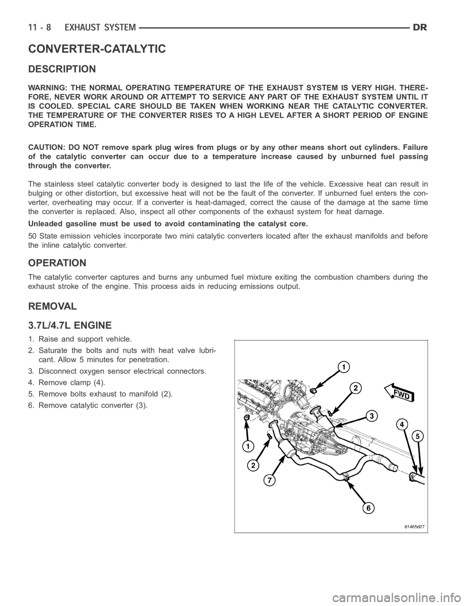
3. Disconnect oxygen sensor electrical connectors.
4. Remove clamp (4).
5. Remove bolts exhaust to manifold (2).
6. Remove catalytic converter (3).
Page 2144 of 5267
5.7L ENGINE
1. Raise and support vehicle.
2. Saturate the bolts and nuts with heat valve lubri-
cant. Allow 5 minutes for penetration.
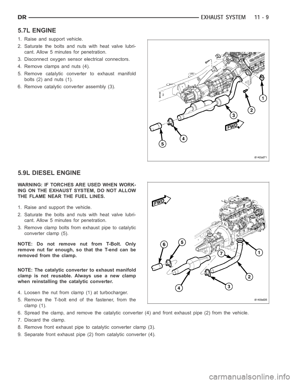
3. Disconnect oxygen sensor electrical connectors.
4. Remove clamps and nuts (4).
5. Remove catalytic converter to exhaust manifold
bolts (2) and nuts (1).
6. Remove catalytic converter assembly (3).
5.9L DIESEL ENGINE
WARNING: IF TORCHES ARE USED WHEN WORK-
ING ON THE EXHAUST SYSTEM, DO NOT ALLOW
THE FLAME NEAR THE FUEL LINES.
1. Raise and support the vehicle.
2. Saturate the bolts and nuts with heat valve lubri-
cant. Allow 5 minutes for penetration.
3. Remove clamp bolts from exhaust pipe to catalytic
converter clamp (5).
NOTE: Do not remove nut from T-Bolt. Only
remove nut far enough, so that the T-end can be
removed from the clamp.
NOTE: The catalytic converter to exhaust manifold
clamp is not reusable. Always use a new clamp
when reinstalling the catalytic converter.
4. Loosen the nut from clamp (1) at turbocharger.
5. Remove the T-bolt end of the fastener, from the
clamp (1).
6. Spread the clamp, and remove the catalytic converter (4) and front exhaust pipe (2) from the vehicle.
7. Discard the clamp.
8. Remove front exhaust pipe to catalytic converter clamp (3).
9. Separate front exhaust pipe (2) from catalytic converter (4).