Page 1517 of 5267
HEAD-CYLINDER-LEFT
DIAGNOSIS AND TESTING - CYLINDER HEAD GASKET
A cylinder head gasket leak can be located between adjacent cylinders or between a cylinder and the adjacent
water jacket.
Possible indications of the cylinder head gasket leaking between adjacent cylinders are:
Loss of engine power
Engine misfiring
Poor fuel economy
Possible indications of the cylinder head gasket leaking between a cylinder and an adjacent water jacket are:
Engine overheating
Loss of coolant
Excessive steam (white smoke) emitting from exhaust
Coolant foaming
CYLINDER-TO-CYLINDER LEAKAGE TEST
To determine if an engine cylinder head gasket is leaking between adjacentcylinders, follow the procedures in Cyl-
inder Compression Pressure Test (Refer to 9 - ENGINE - DIAGNOSIS AND TESTING). An engine cylinder head
gasket leaking between adjacent cylinders will result in approximately a50 - 70% reduction in compression pres-
sure.
CYLINDER-TO-WATER JACKET LEAKAGE TEST
WARNING: USE EXTREME CAUTION WHEN THE ENGINE IS OPERATING WITH COOLANT PRESSURE CAP
REMOVED.
VISUAL TEST METHOD
With the engine cool, remove the coolant pressure cap. Start the engine andallow it to warm up until thermostat
opens.
If a large combustion/compression pressure leak exists, bubbles will be visible in the coolant.
COOLING SYSTEM TESTER METHOD
WARNING: WITH COOLING SYSTEM TESTER IN PLACE, PRESSURE WILL BUILD UP FAST.EXCESSIVE
PRESSURE BUILT UP, BY CONTINUOUS ENGINE OPERATION, MUST BE RELEASED TO A SAFE PRESSURE
POINT. NEVER PERMIT PRESSURE TO EXCEED 138 kPa (20 psi).
Install Cooling System Tester 7700 or equivalent to pressure cap neck. Start the engine and observe the tester’s
pressure gauge. If gauge pulsates with every power stroke of a cylinder a combustion pressure leak is evident.
CHEMICAL TEST METHOD
Combustion leaks into the cooling system can also be checked by using Bloc-Chek Kit C-3685-A or equivalent.
Perform test following the procedures supplied with the tool kit.
REMOVAL
1. Disconnect the negative cable from the battery.
2. Raise the vehicle on a hoist.
3. Disconnect the exhaust pipe at the left side exhaust manifold.
4. Drain the engine coolant (Refer to 7 - COOLING - STANDARD PROCEDURE).
5. Lower the vehicle.
6. Remove the intake manifold (Refer to 9 - ENGINE/MANIFOLDS/INTAKE MANIFOLD - REMOVAL).
Page 1614 of 5267
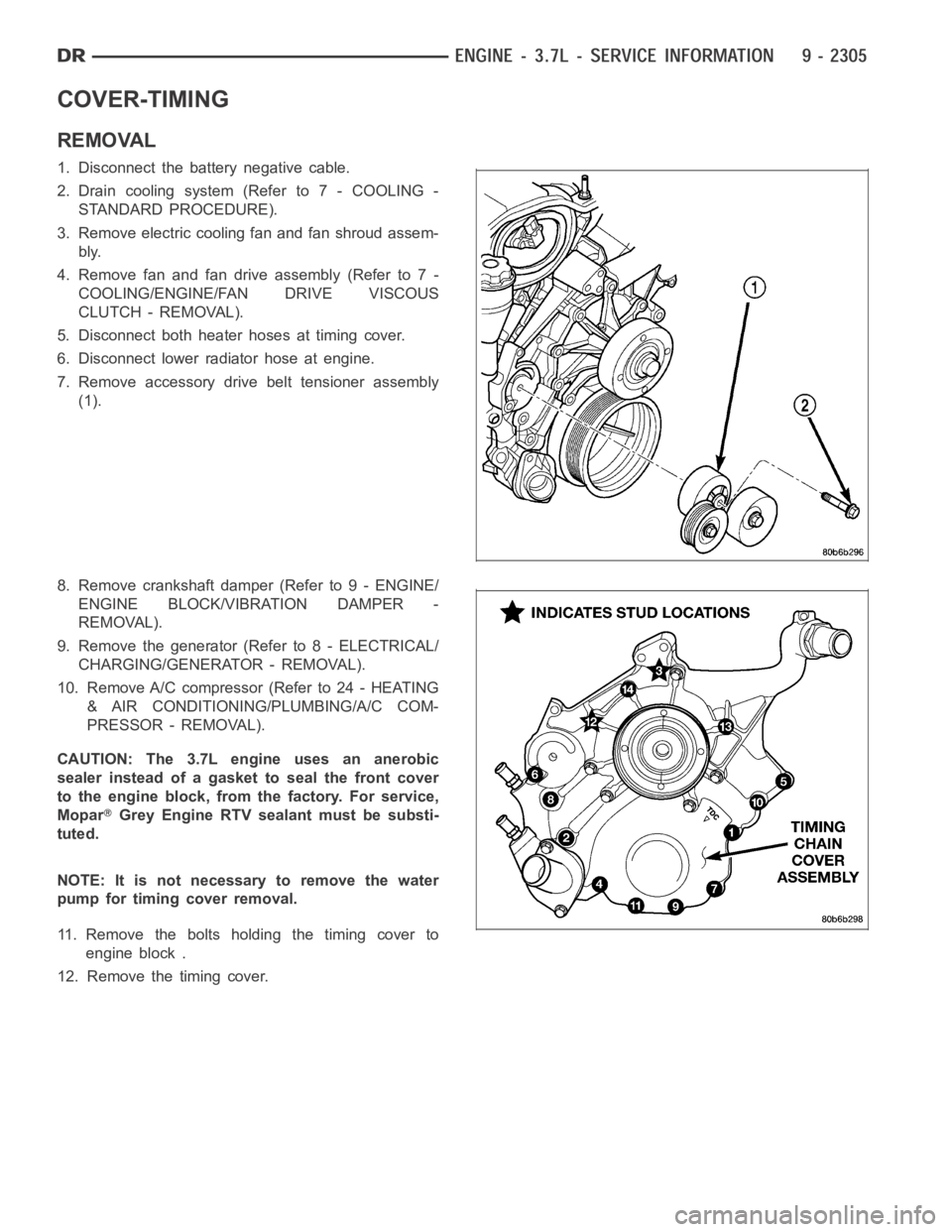
COVER-TIMING
REMOVAL
1. Disconnect the battery negative cable.
2. Drain cooling system (Refer to 7 - COOLING -
STANDARD PROCEDURE).
3. Remove electric cooling fan and fan shroud assem-
bly.
4. Remove fan and fan drive assembly (Refer to 7 -
COOLING/ENGINE/FAN DRIVE VISCOUS
CLUTCH - REMOVAL).
5. Disconnect both heater hoses at timing cover.
6. Disconnect lower radiator hose at engine.
7. Remove accessory drive belt tensioner assembly
(1).
8. Remove crankshaft damper (Refer to 9 - ENGINE/
ENGINE BLOCK/VIBRATION DAMPER -
REMOVAL).
9. Remove the generator (Refer to 8 - ELECTRICAL/
CHARGING/GENERATOR - REMOVAL).
10. Remove A/C compressor (Refer to 24 - HEATING
& AIR CONDITIONING/PLUMBING/A/C COM-
PRESSOR - REMOVAL).
CAUTION: The 3.7L engine uses an anerobic
sealer instead of a gasket to seal the front cover
to the engine block, from the factory. For service,
Mopar
Grey Engine RTV sealant must be substi-
tuted.
NOTE: It is not necessary to remove the water
pump for timing cover removal.
11. Remove the bolts holding the timing cover to
engine block .
12. Remove the timing cover.
Page 1615 of 5267
INSTALLATION
CAUTION: Do not use oil based liquids to clean
timing cover or block surfaces. Use only rubbing
alcohol, along with plastic or wooden scrapers.
Use no wire brushes or abrasive wheels or metal
scrapers, or damage to surfaces could result.
1. Clean timing chain cover and block surface using
rubbing alcohol.
CAUTION: The 3.7L uses a special anerobic sealer
instead of a gasket to seal the timing cover to the
engine block, from the factory. For service repairs,
Mopar
Engine Grey RTV must be used as a sub-
stitute.
2. Inspect the water passage o-rings for any damage,
and replace as necessary.
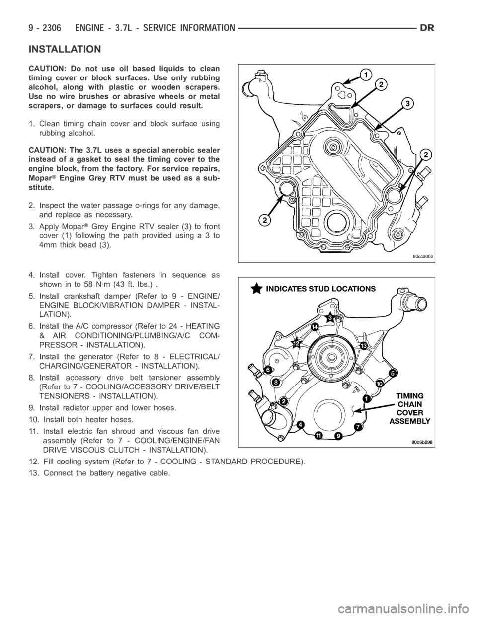
3. Apply Mopar
Grey Engine RTV sealer (3) to front
cover(1)followingthepathprovidedusinga3to
4mm thick bead (3).
4. Install cover. Tighten fasteners in sequence as
showninto58Nꞏm(43ft.lbs.).
5. Install crankshaft damper (Refer to 9 - ENGINE/
ENGINE BLOCK/VIBRATION DAMPER - INSTAL-
LATION).
6. Install the A/C compressor (Refer to 24 - HEATING
& AIR CONDITIONING/PLUMBING/A/C COM-
PRESSOR - INSTALLATION).
7. Install the generator (Refer to 8 - ELECTRICAL/
CHARGING/GENERATOR - INSTALLATION).
8. Install accessory drive belt tensioner assembly
(Refer to 7 - COOLING/ACCESSORY DRIVE/BELT
TENSIONERS - INSTALLATION).
9. Install radiator upper and lower hoses.
10. Install both heater hoses.
11. Install electric fan shroud and viscous fan drive
assembly (Refer to 7 - COOLING/ENGINE/FAN
DRIVE VISCOUS CLUTCH - INSTALLATION).
12. Fill cooling system (Refer to 7 - COOLING - STANDARD PROCEDURE).
13. Connect the battery negative cable.
Page 1632 of 5267
13. Drain cooling system (Refer to 7 - COOLING - STANDARD PROCEDURE).
14. Remove torque converter bolts (Automatic Transmission Only).
15. Remove transmission to engine mounting bolts.
16. Disconnect the engine block heater power cable from the block heater, if equipped.
17. Lower vehicle.
18. Remove throttle body resonator assembly and air inlet hose.
19. Disconnect throttle and speed control cables.
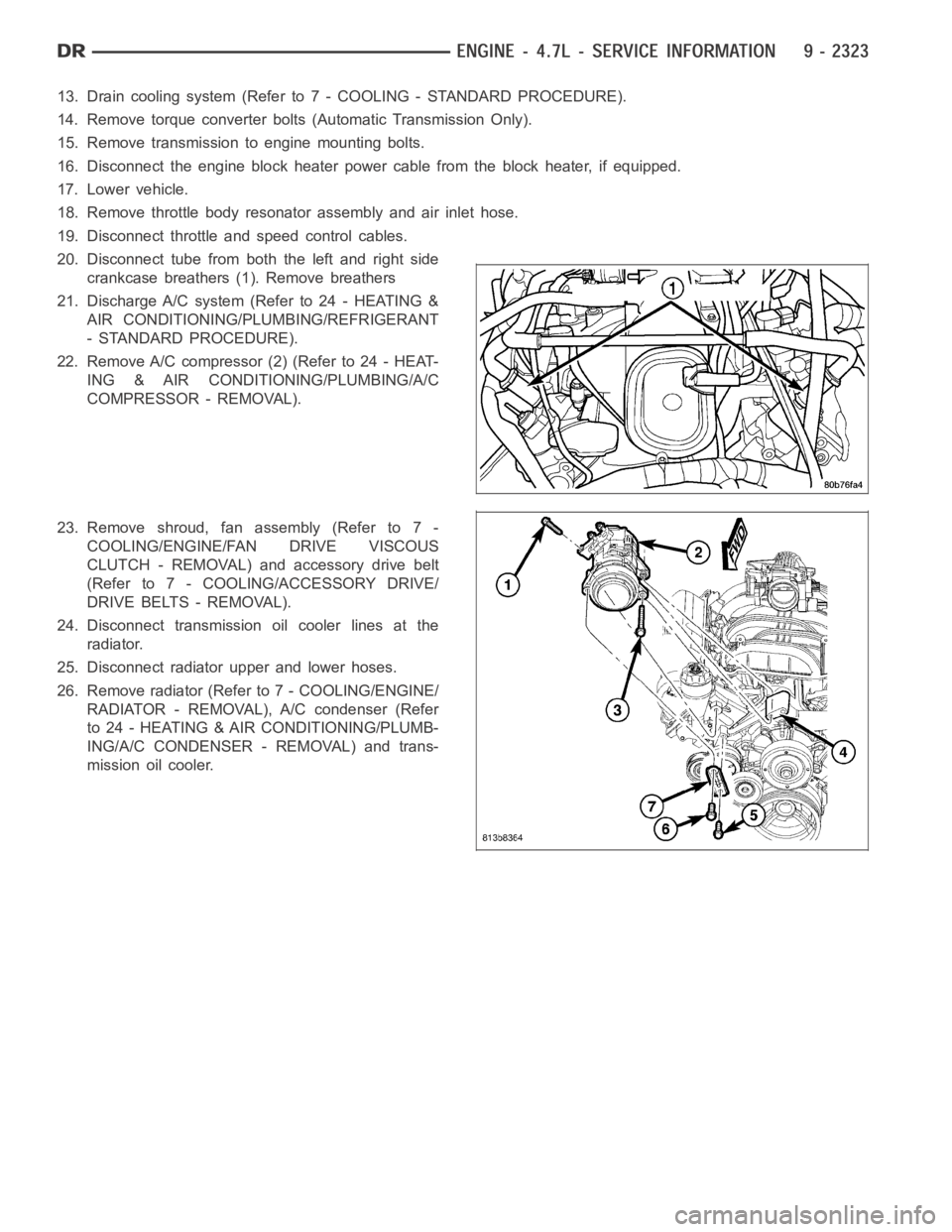
20. Disconnect tube from both the left and right side
crankcase breathers (1). Remove breathers
21. Discharge A/C system (Refer to 24 - HEATING &
AIR CONDITIONING/PLUMBING/REFRIGERANT
- STANDARD PROCEDURE).
22. Remove A/C compressor (2) (Refer to 24 - HEAT-
ING & AIR CONDITIONING/PLUMBING/A/C
COMPRESSOR - REMOVAL).
23. Remove shroud, fan assembly (Refer to 7 -
COOLING/ENGINE/FAN DRIVE VISCOUS
CLUTCH - REMOVAL) and accessory drive belt
(Refer to 7 - COOLING/ACCESSORY DRIVE/
DRIVE BELTS - REMOVAL).
24. Disconnect transmission oil cooler lines at the
radiator.
25. Disconnect radiator upper and lower hoses.
26. Remove radiator (Refer to 7 - COOLING/ENGINE/
RADIATOR - REMOVAL), A/C condenser (Refer
to 24 - HEATING & AIR CONDITIONING/PLUMB-
ING/A/C CONDENSER - REMOVAL) and trans-
mission oil cooler.
Page 1638 of 5267
12. Position and install heater hoses (1) and tubes
onto intake manifold.
13. Install the heater hoses onto the heater core and
the engine front cover, and install clips (2).
14. Install generator (3) (Refer to 8 - ELECTRICAL/
CHARGING/GENERATOR - INSTALLATION).
15. Install A/C condenser (Refer to 24 - HEATING & AIR CONDITIONING/PLUMBING/A/C CONDENSER - INSTAL-
LATION), radiator (Refer to 7 - COOLING/ENGINE/RADIATOR - INSTALLATION)and transmission oil cooler.
16. Connect radiator upper and lower hoses.
17. Connect the transmission oil cooler lines to the radiator.
18. Install accessory drive belt (Refer to 7 - COOLING/ACCESSORY DRIVE/DRIVE BELTS - INSTALLATION), fan
assembly and shroud (Refer to 7 - COOLING/ENGINE/FAN DRIVE VISCOUS CLUTCH- INSTALLATION).
Page 1640 of 5267
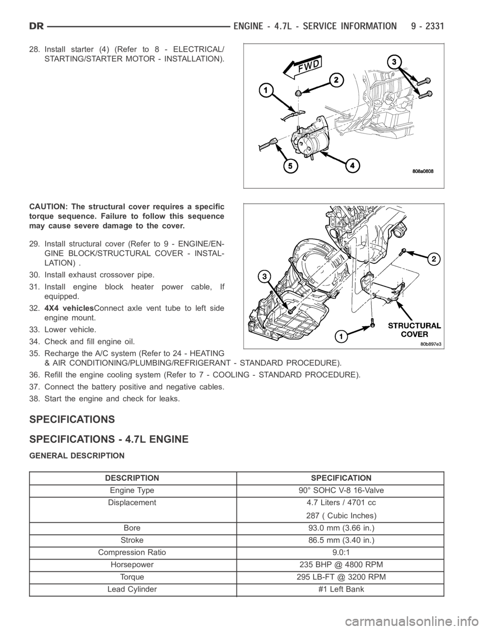
28. Install starter (4) (Refer to 8 - ELECTRICAL/
STARTING/STARTER MOTOR - INSTALLATION).
CAUTION: The structural cover requires a specific
torque sequence. Failure to follow this sequence
may cause severe damage to the cover.
29. Install structural cover (Refer to 9 - ENGINE/EN-
GINE BLOCK/STRUCTURAL COVER - INSTAL-
LATION) .
30. Install exhaust crossover pipe.
31. Install engine block heater power cable, If
equipped.
32.4X4 vehiclesConnect axle vent tube to left side
engine mount.
33. Lower vehicle.
34. Check and fill engine oil.
35. Recharge the A/C system (Refer to 24 - HEATING
& AIR CONDITIONING/PLUMBING/REFRIGERANT - STANDARD PROCEDURE).
36. Refill the engine cooling system (Refer to 7 - COOLING - STANDARD PROCEDURE).
37. Connect the battery positive and negative cables.
38. Start the engine and check for leaks.
SPECIFICATIONS
SPECIFICATIONS - 4.7L ENGINE
GENERAL DESCRIPTION
DESCRIPTION SPECIFICATION
Engine Type 90° SOHC V-8 16-Valve
Displacement 4.7 Liters / 4701 cc
287 ( Cubic Inches)
Bore 93.0 mm (3.66 in.)
Stroke 86.5 mm (3.40 in.)
Compression Ratio 9.0:1
Horsepower 235 BHP @ 4800 RPM
Torque 295 LB-FT @ 3200 RPM
Lead Cylinder #1 Left Bank
Page 1653 of 5267
CYLINDER HEAD
DESCRIPTION
DESCRIPTION - CYLINDER HEAD
The cylinder heads are made of an aluminum alloy. The cylinder head features two valves per cylinder with pressed
in powdered metal valve guides. The cylinder heads also provide enclosures for the timing chain drain, necessitating
unique left and right cylinder heads.
DESCRIPTION - VALVE GUIDES
The valve guides are made of powered metal and are pressed into the cylinderhead. The guides are not replace-
able or serviceable, and valve guide reaming is not recommended. If the guides are worn beyond acceptable limits,
replace the cylinder heads.
DIAGNOSIS AND TESTING
CYLINDER HEAD GASKET
A cylinder head gasket leak can be located between adjacent cylinders or between a cylinder and the adjacent
water jacket.
Possible indications of the cylinder head gasket leaking between adjacent cylinders are:
Loss of engine power
Engine misfiring
Poor fuel economy
Possible indications of the cylinder head gasket leaking between a cylinder and an adjacent water jacket are:
Engine overheating
Loss of coolant
Excessive steam (white smoke) emitting from exhaust
Coolant foaming
CYLINDER-TO-CYLINDER LEAKAGE TEST
To determine if an engine cylinder head gasket is leaking between adjacentcylinders, follow the procedures in Cyl-
inder Compression Pressure Test (Refer to 9 - ENGINE - DIAGNOSIS AND TESTING). An engine cylinder head
gasket leaking between adjacent cylinders will result in approximately a50 - 70% reduction in compression pres-
sure.
CYLINDER-TO-WATER JACKET LEAKAGE TEST
WARNING: USE EXTREME CAUTION WHEN THE ENGINE IS OPERATING WITH COOLANT PRESSURE CAP
REMOVED.
VISUAL TEST METHOD
With the engine cool, remove the coolant pressure cap. Start the engine andallow it to warm up until thermostat
opens.
If a large combustion/compression pressure leak exists, bubbles will be visible in the coolant.
COOLING SYSTEM TESTER METHOD
WARNING: WITH COOLING SYSTEM TESTER IN PLACE, PRESSURE WILL BUILD UP FAST.EXCESSIVE
PRESSURE BUILT UP, BY CONTINUOUS ENGINE OPERATION, MUST BE RELEASED TO A SAFE PRESSURE
POINT. NEVER PERMIT PRESSURE TO EXCEED 138 kPa (20 psi).
Page 1735 of 5267
MANIFOLD - EXHAUST
DESCRIPTION
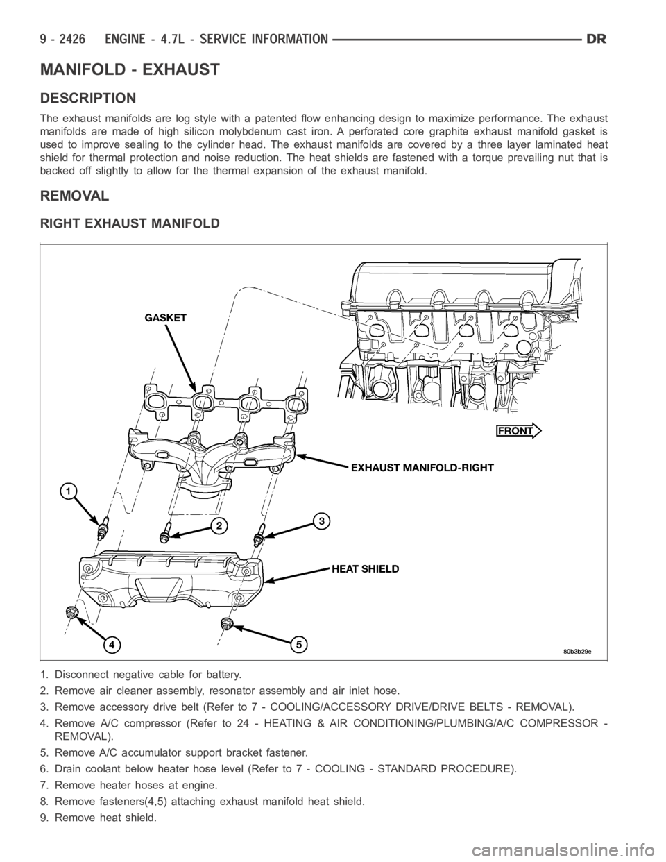
The exhaust manifolds are log style with a patented flow enhancing design to maximize performance. The exhaust
manifolds are made of high silicon molybdenum cast iron. A perforated coregraphite exhaust manifold gasket is
used to improve sealing to the cylinder head. The exhaust manifolds are covered by a three layer laminated heat
shield for thermal protection and noise reduction. The heat shields are fastened with a torque prevailing nut that is
backed off slightly to allow for the thermal expansion of the exhaust manifold.
REMOVAL
RIGHT EXHAUST MANIFOLD
1. Disconnect negative cable for battery.
2. Remove air cleaner assembly, resonator assembly and air inlet hose.
3. Remove accessory drive belt (Refer to 7 - COOLING/ACCESSORY DRIVE/DRIVE BELTS - REMOVAL).
4. Remove A/C compressor (Refer to 24 -HEATING & AIR CONDITIONING/PLUMBING/A/C COMPRESSOR -
REMOVAL).
5. Remove A/C accumulator support bracket fastener.
6. Drain coolant below heater hose level (Refer to 7 - COOLING - STANDARD PROCEDURE).
7. Remove heater hoses at engine.
8. Remove fasteners(4,5) attaching exhaust manifold heat shield.
9. Remove heat shield.