2006 DODGE RAM SRT-10 Fuel injector removal
[x] Cancel search: Fuel injector removalPage 1917 of 5267
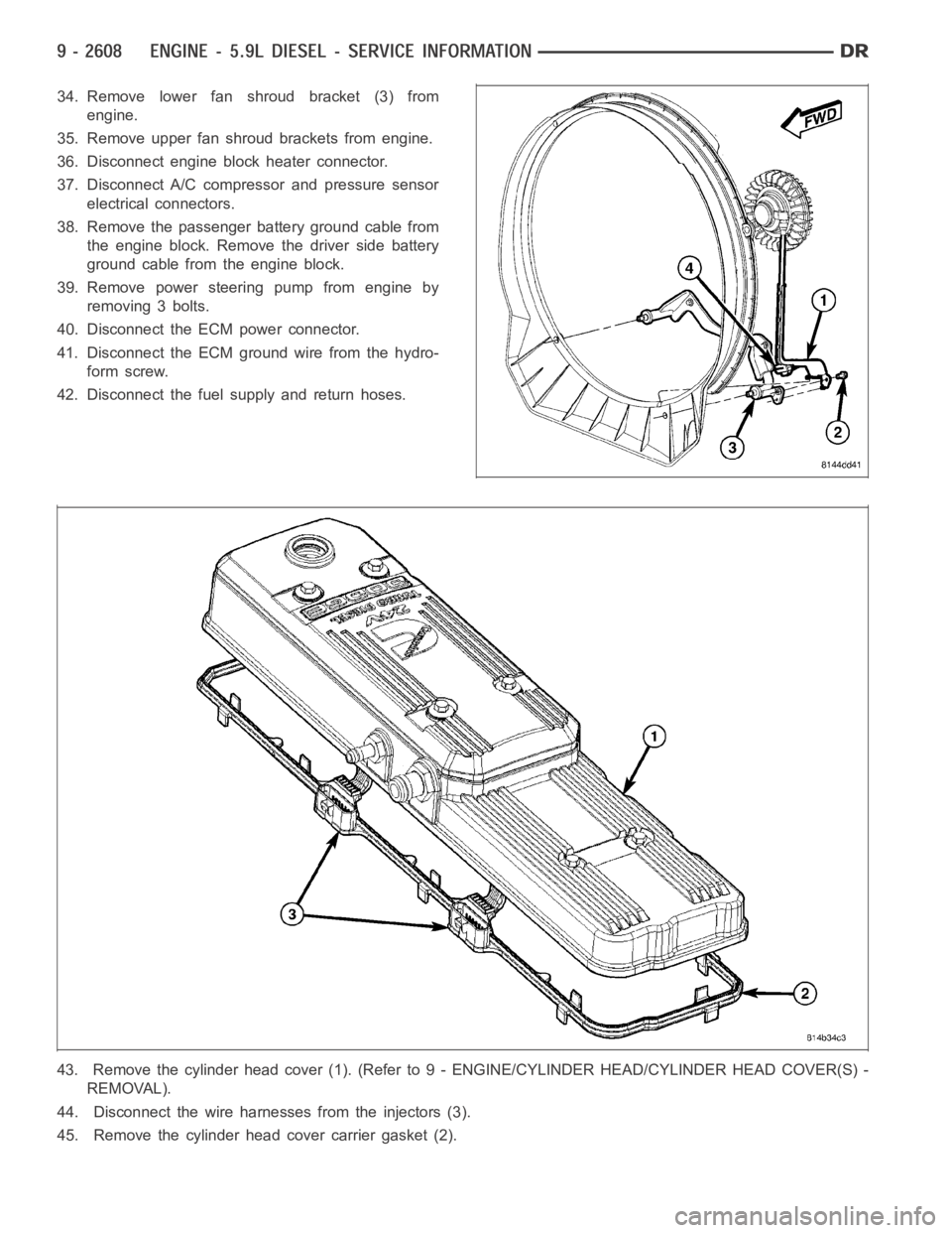
34. Remove lower fan shroud bracket (3) from
engine.
35. Remove upper fan shroud brackets from engine.
36. Disconnect engine block heater connector.
37. Disconnect A/C compressor and pressure sensor
electrical connectors.
38. Remove the passenger battery ground cable from
the engine block. Remove the driver side battery
ground cable from the engine block.
39. Remove power steering pump from engine by
removing 3 bolts.
40. Disconnect the ECM power connector.
41. Disconnect the ECM ground wire from the hydro-
form screw.
42. Disconnect the fuel supply and return hoses.
43. Remove the cylinder head cover (1). (Refer to 9 - ENGINE/CYLINDER HEAD/CYLINDER HEAD COVER(S) -
REMOVAL).
44. Disconnect the wire harnesses from the injectors (3).
45. Remove the cylinder head cover carrier gasket (2).
Page 1933 of 5267
CYLINDER HEAD
DESCRIPTION
The cylinder head is constructed of cast iron and is a one piece cross flow design with four valves per cylinder. The
arrangement of two intake and two exhaust valves per cylinder allows for a centrally located injector. The cylinder
head also includes an integral intake manifold, an integral thermostat housing, and a longitudal fuel return rifle,
which exits at the rear of the head. The 24 valve design also includes integrally cast valve guides and hardened
intake and exhaust valve seat inserts.
REMOVAL
1. Disconnect battery negative cables.
2. Raise vehicle on hoist.
3. Drain engine coolant.
4. Disconnect exhaust pipe from turbocharger elbow.
5. Remove turbocharger drain tube bolts at turbocharger. Cap off ports to prevent dirt or foreign material from enter-
ing.
6. Lower vehicle.
7. Disconnect air inlet temperature/pressure sensor.
8. Remove air cleaner housing and snorkel from the vehicle. Cap off turbocharger air inlet to prevent intrusion of
dirt or foreign material.
9. Disconnect cab heater core supply and return hoses from the cylinder head and heater pipe.
10. Disconnect turbocharger oil supply line at the turbocharger end. Cap off open ports to prevent intrusion of dirt
or foreign material.
11. Remove exhaust manifold-to-cylinder head bolts, spacers, heat shield, retention straps, and cab heater plumb-
ing. Remove exhaust manifold and turbocharger from the vehicle as an assembly.
12. Remove cooling fan/drive/shroud assembly. (Refer to 7 - COOLING/ENGINE/RADIATOR FAN - REMOVAL)
13. Remove accessory drive belt (Refer to 7 - COOLING/ACCESSORY DRIVE/DRIVE BELTS - REMOVAL).
14. Remove cooling fan support from cylinder block.
15. Remove upper generator bolt, loosen lower generator bolt, and rotate generator away from cylinder head.
16. Disconnect radiator upper hose from the thermostat housing.
17. Disconnect the Intake Air Temperature/Manifold Air Pressure, and Coolant Temperature sensor connectors.
18. Remove the engine harness to cylinder head attaching bolts and P-clipsat front of head.
19. Remove the intake air grid heater wires from the grid heater.
20. Remove engine oil level indicator tube attaching bolt at fuel filter housing bracket and inlet air connection..
21. Remove the charge air cooler-to-air inlet housing pipe.
22. Remove the engine wire harness attaching bolt and wire harness push-infastener from air inlet housing.
23. Remove the air inlet housing and intake grid heater from the intake manifold cover.
24. Remove the two grid heater harness-to-cylinder head attaching bolts at front of cylinder head.
NOTE: Extreme care should be used to keep dirt/debris from entering the fuel lines. Plastic caps should be
used on the ends of the fuel lines.
25.Remove the high pressure pump to fuel rail fuel line as follows:
a. Loosen fuel line nuts at fuel pump and at fuel rail.
b. Use a back-up wrench on the fitting at the fuel pump to keep it from loosening.
26. Remove the fuel rail to cylinder head fuel lines as follows:
a. Loosen No. 6 high pressure fuel line shield and position out of way.
b. Loosen the fuel line nuts at the fuel rail and at the cylinder head. Use a back-up wrench on HPC nut.
c. Remove the fuel line bracket bolts at the intake manifold cover.
Page 1934 of 5267
27. Remove the engine lift bracket from the rear of the cylinder head.
28. Remove the fuel rail as follows:
a. Remove fuel rail pressure sensor connector.
b. Remove banjo fitting at pressure limiting valve.
c. Remove fuel rail bolts and fuel rail.
29. Remove the low pressure lines as follows:
a. Remove the fuel drain banjo fitting on the front side of fuel filter housing.
b. Remove the fuel drain banjo fitting on rear side of fuel filter housing.
c. Remove the fuel drain line support bracket on rear side of filter housing.
d. Disconnect fuel drain hose.
e. Remove banjo fitting at bottom of fuel filter housing.
f. Disconnect fuel supply hose at fuel filter.
30. Disconnect fuel heater, and water in fuel sensor.
31. Remove the fuel filter assembly-to-cylinder head bolts and remove filter assembly from vehicle.
32. Remove wire harness P-clip from cylinder head (located behind filter housing).
NOTE: For early builds. Verify that the cylinder head cover ground spring is retained in the cylinder head
cover.
33. Remove the cylinder head cover (Refer to 9 - ENGINE/CYLINDER HEAD/CYLINDER HEAD COVER(S) -
REMOVAL).
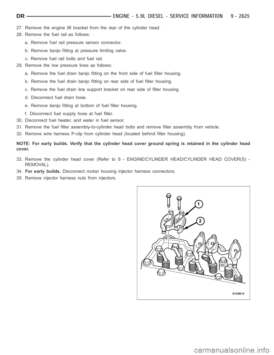
34.For early builds.Disconnect rocker housing injector harness connectors.
35. Remove injector harness nuts from injectors.
Page 1935 of 5267
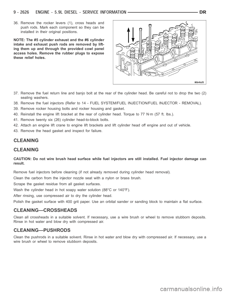
36. Remove the rocker levers (1), cross heads and
push rods. Mark each component so they can be
installed in their original positions.
NOTE: The #5 cylinder exhaust and the #6 cylinder
intake and exhaust push rods are removed by lift-
ing them up and through the provided cowl panel
access holes. Remove the rubber plugs to expose
these relief holes.
37. Remove the fuel return line and banjo bolt at the rear of the cylinder head. Be careful not to drop the two (2)
sealing washers.
38. Remove the fuel injectors (Refer to 14 - FUEL SYSTEM/FUEL INJECTION/FUEL INJECTOR - REMOVAL).
39. Remove rocker housing bolts and rocker housing and gasket.
40. Reinstall the engine lift bracket at the rear of cylinder head. Torque to77Nꞏm(57ft.lbs.).
41. Remove twenty six (26) cylinder head-to-block bolts.
42. Attach an engine lift crane to engine lift brackets and lift cylinder head off engine and out of vehicle.
43. Remove the head gasket and inspect for failure.
CLEANING
CLEANING
CAUTION: Do not wire brush head surface while fuel injectors are still installed. Fuel injector damage can
result.
Remove fuel injectors before cleaning (if not already removed during cylinder head removal).
Clean the carbon from the injector nozzle seat with a nylon or brass brush.
Scrape the gasket residuefrom all gasket surfaces.
Wash the cylinder head in hot soapy water solution (88°C or 140°F).
After rinsing, use compressed air to dry the cylinder head.
Polish the gasket surface with 400 grit paper. Use an orbital sander or sanding block to maintain a flat surface.
CLEANING—CROSSHEADS
Clean all crossheads in a suitable solvent. If necessary, use a wire brush or wheel to remove stubborn deposits.
Rinse in hot water and blow dry with compressed air.
CLEANING—PUSHRODS
Clean the pushrods in a suitable solvent. Rinse in hot water and blow dry with compressed air. If necessary, use a
wire brush or wheel to remove stubborn deposits.
Page 1952 of 5267
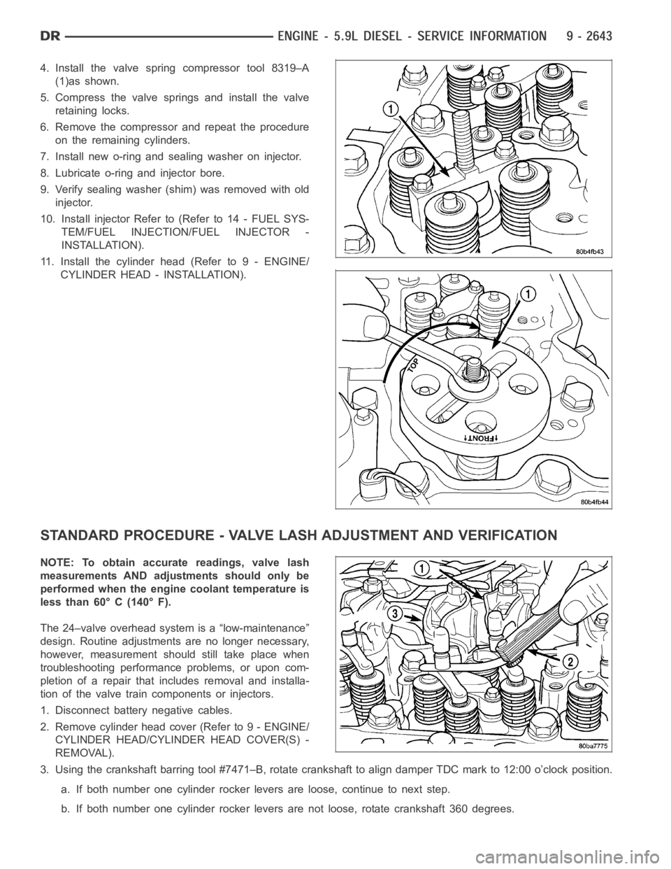
4. Install the valve spring compressor tool 8319–A
(1)as shown.
5. Compress the valve springs and install the valve
retaining locks.
6. Remove the compressor and repeat the procedure
on the remaining cylinders.
7. Install new o-ring and sealing washer on injector.
8. Lubricate o-ring and injector bore.
9. Verify sealing washer (shim) was removed with old
injector.
10. Install injector Refer to (Refer to 14 - FUEL SYS-
TEM/FUEL INJECTION/FUEL INJECTOR -
INSTALLATION).
11. Install the cylinder head (Refer to 9 - ENGINE/
CYLINDER HEAD - INSTALLATION).
STANDARD PROCEDURE - VALVE LASH ADJUSTMENT AND VERIFICATION
NOTE: To obtain accurate readings, valve lash
measurements AND adjustments should only be
performed when the engine coolant temperature is
less than 60° C (140° F).
The 24–valve overhead system is a “low-maintenance”
design. Routine adjustments are no longer necessary,
however, measurement should still take place when
troubleshooting performance problems, or upon com-
pletion of a repair that includes removal and installa-
tion of the valve train components or injectors.
1. Disconnect battery negative cables.
2. Remove cylinder head cover (Refer to 9 - ENGINE/
CYLINDER HEAD/CYLINDER HEAD COVER(S) -
REMOVAL).
3. Using the crankshaft barring tool #7471–B, rotate crankshaft to align damper TDC mark to 12:00 o’clock position.
a. If both number one cylinder rocker levers are loose, continue to next step.
b. If both number one cylinder rocker levers are not loose, rotate crankshaft 360 degrees.
Page 1953 of 5267
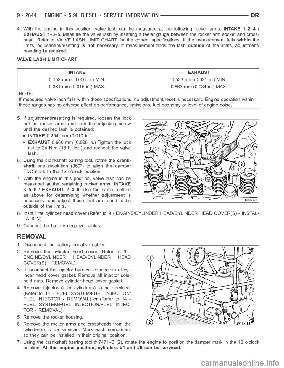
4. With the engine in this position, valve lash can be measured at the following rocker arms:INTAKE 1–2–4 /
EXHAUST 1–3–5. Measure the valve lash by inserting a feeler gauge between the rocker arm socket and cross-
head. Refer to VALVE LASH LIMIT CHART for the correct specifications. If the measurement fallswithinthe
limits, adjustment/resettingis notnecessary. If measurement finds the lashoutsideof the limits, adjustment/
resettingisrequired.
VALVE LASH LIMIT CHART
INTAKE EXHAUST
0.152 mm ( 0.006 in.) MIN. 0.533 mm (0.021 in.) MIN.
0.381 mm (0.015 in.) MAX. 0.863 mm (0.034 in.) MAX.
NOTE:
If measured valve lash falls within these specifications, no adjustment/reset is necessary. Engine operation within
these ranges has no adverse affect on performance, emissions, fuel economy or level of engine noise.
5. If adjustment/resetting is required, loosen the lock
nut on rocker arms and turn the adjusting screw
until the desired lash is obtained:
INTAKE0.254 mm (0.010 in.)
EXHAUST0.660 mm (0.026 in.) Tighten the lock
nut to 24 Nꞏm (18 ft. lbs.) and recheck the valve
lash.
6. Using the crankshaft barring tool, rotate thecrank-
shaftone revolution (360°) to align the damper
TDC mark to the 12 o’clock position.
7. With the engine in this position, valve lash can be
measured at the remaining rocker arms:INTAKE
3–5–6 / EXHAUST 2–4–6. Use the same method
as above for determining whether adjustment is
necessary, and adjust those that are found to be
outside of the limits.
8. Install the cylinder head cover (Refer to 9 - ENGINE/CYLINDER HEAD/CYLINDER HEAD COVER(S) - INSTAL-
LATION).
9. Connect the battery negative cables.
REMOVAL
1. Disconnect the battery negative cables.
2. Remove the cylinder head cover (Refer to 9 -
ENGINE/CYLINDER HEAD/CYLINDER HEAD
COVER(S) - REMOVAL).
3. Disconnect the injector harness connectors at cyl-
inder head cover gasket. Remove all injector sole-
noid nuts. Remove cylinder head cover gasket.
4. Remove injector(s) for cylinder(s) to be serviced.
(Refer to 14 - FUEL SYSTEM/FUEL INJECTION/
FUELINJECTOR-REMOVAL)or(Referto14-
FUEL SYSTEM/FUEL INJECTION/FUEL INJEC-
TOR - REMOVAL).
5. Remove the rocker housing.
6. Remove the rocker arms and crossheads from the
cylinder(s) to be serviced. Mark each component
so they can be installed in their original position.
7. Using the crankshaft barring tool # 7471–B (2), rotate the engine to position the damper mark in the 12 o’clock
position.At this engine position, cylinders #1 and #6 can be serviced.
Page 1954 of 5267
8. Remove the accessory drive belt (Refer to 7 - COOLING/ACCESSORY DRIVE/DRIVE BELTS - REMOVAL).
9. With the damper TDC mark in the 12 o’clock position, add a paint mark anywhere on the gear housing cover
next to the crankshaft damper. Place another mark on the vibration damper in alignment with the mark you just
made on the cover.
10. Divide the crankshaft damper into three equally sized segments as follows:
a. Using a tape measure, measure the circumference of the crankshaft damper and divide the measurement by
three (3).
b. Measure that distance in a counterclockwise direction from the first balancer mark and place another mark
on the balancer.
c. From the second damper mark, again measure in a counterclockwise direction and place a mark on the
damper at the same distance you measured when placing the second damper mark. The damper should
now be marked in three equally spaced locations and the damper TDC mark should be in the 12 o’clock
position.
d. Remove injectors, fuel lines, and high pressure connectors for every cylinder that requires repair.
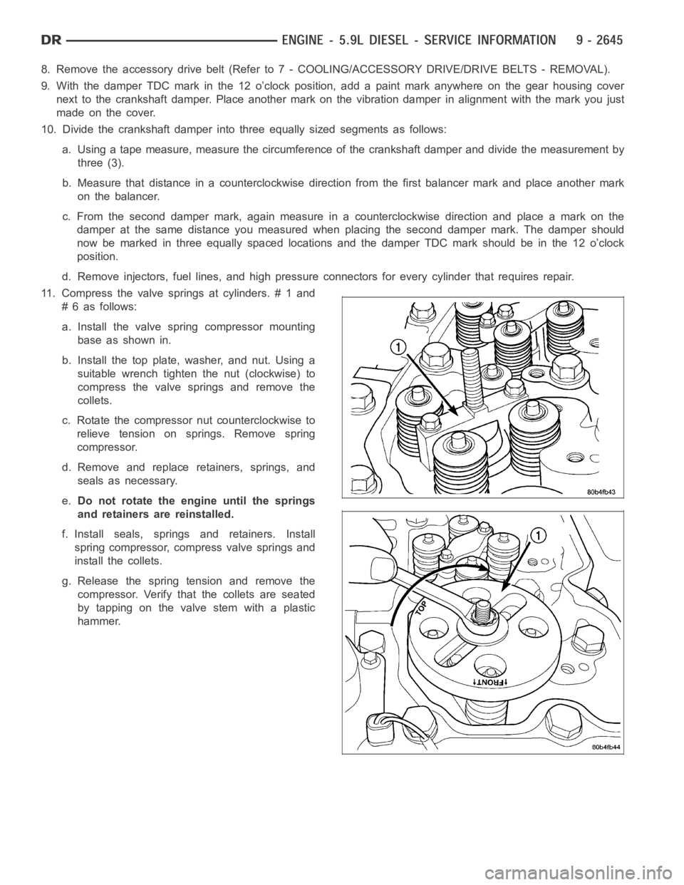
11. Compress the valve springs at cylinders. # 1 and
# 6 as follows:
a. Install the valve spring compressor mounting
base as shown in.
b. Install the top plate, washer, and nut. Using a
suitable wrench tighten the nut (clockwise) to
compress the valve springs and remove the
collets.
c. Rotate the compressor nut counterclockwise to
relieve tension on springs. Remove spring
compressor.
d. Remove and replace retainers, springs, and
seals as necessary.
e.Do not rotate the engine until the springs
and retainers are reinstalled.
f. Install seals, springs and retainers. Install
spring compressor, compress valve springs and
install the collets.
g. Release the spring tension and remove the
compressor. Verify that the collets are seated
by tapping on the valve stem with a plastic
hammer.
Page 2015 of 5267
VALVE TIMING
STANDARD PROCEDURE - TIMING VERIFICATION
1. Remove the cylinder head cover (Refer to 9 - ENGINE/CYLINDER HEAD/CYLINDER HEAD COVER(S) -
REMOVAL).
2. Remove fuel injector from cylindernumber 1 (Refer to 14 - FUEL SYSTEM/FUEL INJECTION/FUEL INJECTOR
- REMOVAL).
3. Using Special Tool 7471B rotate the engine until the TDC mark on the damper is at 12 o’clock.
4. Using a 8 in.x 1/4 in. dowel rod inserted into cylinder number 1, rock the crankshaft back and forth to verify
piston number 1 is at TDC.
5. With cylinder number still at TDC, inspect the keyway on the crankshaft gear for proper alignment (12 o’clock
position).
6. If the keyway is not at 12 o’clock position replace the crankshaft gear assembly.
7. If the keyway is at 12 o’clock position, remove front gear cover and verify timing mark alignment between the
camshaft gear and crankshaft gear, if not aligned inspect keyway on camshaft gear.
8. Inspect keyway on camshaft gear for proper alignment with the key in the camshaft, if alignment is off replace
the camshaft/gear assembly.
9. If timing marks alignment is off and no damage is found at either the crankshaft or camshaft gear keyways,
realign timing marks as necessary.