2006 DODGE RAM SRT-10 Fuel injector removal
[x] Cancel search: Fuel injector removalPage 2242 of 5267

8. Connect other end of jumper wire to positive side of battery.
9. Connect one end of a second jumper wire to remaining injector terminal.
CAUTION: Powering an injector for more than a few seconds will permanentlydamage the injector.
10. Momentarily touch other end of jumper wire to negative terminal of battery for no more than a few seconds.
11. Place a rag or towel below fuel line quick-connect fitting at fuel rail.
12. Disconnect quick-connect fitting at fuel rail. Refer to Quick-Connect Fittings.
13. Return fuel pump relay to PDC.
14. One or more Diagnostic Trouble Codes (DTC’s) may have been stored in PCMmemory due to fuel pump relay
removal. The DRB
scantoolmustbeusedtoeraseaDTC.
STANDARD PROCEDURE - DRAINING FUEL TANK - EXCEPT DIESEL
WARNING: The fuel system may be under constant fuel pressure even with the engine off. This pressure
must be released before servicing fuel tank.
Two different procedures may be used to drain fuel tank: through the fuel fill fitting on tank, or using a diagnostic
scan tool to activate the fuel pump relay. Due to a one-way check valve installed into the fuel fill opening fitting at
the tank, the tank cannot be drained conventionally at the fill cap.
The quickest draining procedure involves removing the rubber fuel fill hose at the fuel tank.
As an alternative procedure, the electric fuel pump may be activated allowingtanktobedrainedatfuelrailcon-
nection. Refer to diagnostic scan tool for fuel pump activation procedures. Before disconnecting fuel line at fuel rail,
release fuel pressure. Refer to the Fuel System Pressure Release Procedure for procedures. Attach end of special
test hose tool number 6631 or 6539 at fuel rail disconnection (tool number 6631isusedon5/16”fuellineswhile
tool number 6539 is used on 3/8” fuel lines). Position opposite end of this hose tool to an approved gasoline drain-
ing station. Activate fuel pump and drain tank until empty.
If electric fuel pump is not operating, fuel must be drained through fuel fill fitting at tank. Refer to following proce-
dures.
1. Release fuel system pressure.
2. Raise vehicle.
3. Thoroughly clean area around fuel fill fitting and rubber fuel fill hoseat tank.
4. If vehicle is equipped with 4 doors and a 6 foot (short) box, remove left-rear tire/wheel.
5. Loosen clamp and disconnect rubber fuel fill hose at tank fitting. Usingan approved gas holding tank, drain fuel
tank through this fitting.
SPECIFICATIONS
FUEL SYSTEM PRESSURE
58 psi +/- 2 psi
TORQUE - EXCEPT DIESEL
DESCRIPTION N-m Ft. Lbs. In. Lbs.
Accelerator Pedal Bracket
Mounting12 - 105
Accelerator Pedal Position
Sensor Bracket-to-Battery
Tray Bolts3-30
Crankshaft Position
Sensor - 3.7L28 21 -
Crankshaft Position
Sensor - 4.7L28 21 -
Page 2259 of 5267
RAIL - FUEL
DESCRIPTION
The fuel injector rail is used to mount the fuel injectors to the engine.
OPERATION
High pressure from the fuel pump is routed to the fuel rail. The fuel rail then supplies the necessary fuel to each
individual fuel injector.
A quick-connect fitting with a safety latch clip is used to attach the fuel linetothefuelrail.
The fuel rail is not repairable.
CAUTION: The left and right sections of the fuel rail are connected with either a flexible connecting hose, or
joints. Do not attempt to separate the rail halves at these connecting hoseor joints. Due to the design of
the connecting hose or joint, it does not use any clamps. Never attempt to install a clamping device of any
kind to the hose or joint. When removing the fuel rail assembly for any reason, be careful not to bend or
kink the connecting hose or joint.
REMOVAL
3.7L V-6
WARNING: The fuel system is under constant pressure even with engine off. Before servicing fuel rail, fuel
system pressure must be released.
CAUTION: The left and right fuel rails are replaced as an assembly. Do not attempt to separate rail halves
at connector tubes. Due to design of tubes, it does not use any clamps. Neverattempt to install a clamping
device of any kind to tubes. When removing fuel rail assembly for any reason, be careful not to bend or
kink tubes.
1. Remove fuel tank filler tube cap.
2. Perform Fuel System Pressure Release Procedure.
(Refer to 14 - FUEL SYSTEM/FUEL DELIVERY -
STANDARD PROCEDURE)
3. Remove negative battery cable at battery.
4. Remove air duct at throttle body air box.
5. Remove air box at throttle body.
6. Remove air resonator mounting bracket at front of
throttle body (2 bolts).
7. Disconnect fuel line latch clip and fuel line at fuel
rail. A special tool will be necessary for fuel line
disconnection. (Refer to 14 - FUEL SYSTEM/FUEL
DELIVERY/QUICK CONNECT FITTING - STAN-
DARD PROCEDURE)
8. Remove necessary vacuumlines at throttle body.
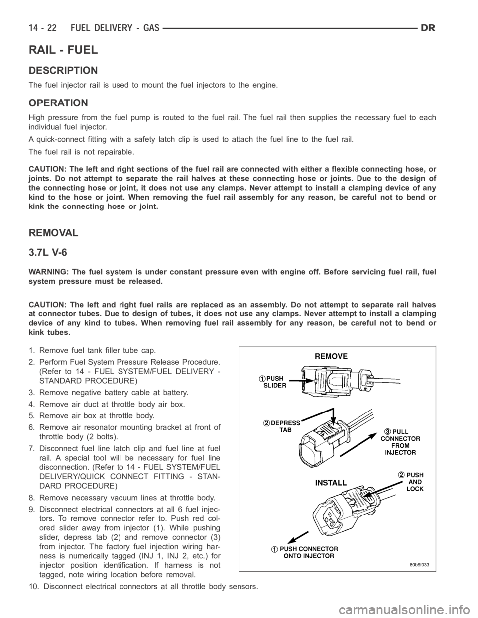
9. Disconnect electrical connectors at all 6 fuel injec-
tors. To remove connector refer to. Push red col-
ored slider away from injector (1). While pushing
slider, depress tab (2) and remove connector (3)
from injector. The factory fuel injection wiring har-
ness is numerically tagged (INJ 1, INJ 2, etc.) for
injector position identification. If harness is not
tagged, note wiring location before removal.
10. Disconnect electrical connectors at all throttle body sensors.
Page 2260 of 5267
11. Remove 6 ignition coils. (Refer to 8 - ELECTRICAL/IGNITION CONTROL/IGNITION COIL - REMOVAL)
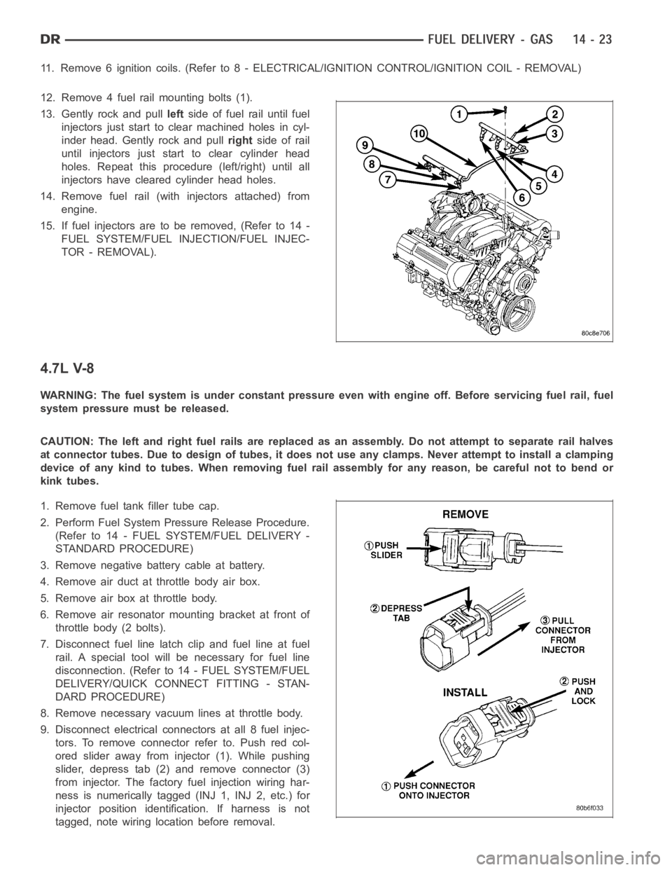
12. Remove 4 fuel rail mounting bolts (1).
13. Gently rock and pullleftside of fuel rail until fuel
injectors just start to clear machined holes in cyl-
inder head. Gently rock and pullrightside of rail
until injectors just start to clear cylinder head
holes. Repeat this procedure (left/right) until all
injectors have cleared cylinder head holes.
14. Remove fuel rail (with injectors attached) from
engine.
15. If fuel injectors are to be removed, (Refer to 14 -
FUEL SYSTEM/FUEL INJECTION/FUEL INJEC-
TOR - REMOVAL).
4.7L V-8
WARNING: The fuel system is under constant pressure even with engine off. Before servicing fuel rail, fuel
system pressure must be released.
CAUTION: The left and right fuel rails are replaced as an assembly. Do not attempt to separate rail halves
at connector tubes. Due to design of tubes, it does not use any clamps. Neverattempt to install a clamping
device of any kind to tubes. When removing fuel rail assembly for any reason, be careful not to bend or
kink tubes.
1. Remove fuel tank filler tube cap.
2. Perform Fuel System Pressure Release Procedure.
(Refer to 14 - FUEL SYSTEM/FUEL DELIVERY -
STANDARD PROCEDURE)
3. Remove negative battery cable at battery.
4. Remove air duct at throttle body air box.
5. Remove air box at throttle body.
6. Remove air resonator mounting bracket at front of
throttle body (2 bolts).
7. Disconnect fuel line latch clip and fuel line at fuel
rail. A special tool will be necessary for fuel line
disconnection. (Refer to 14 - FUEL SYSTEM/FUEL
DELIVERY/QUICK CONNECT FITTING - STAN-
DARD PROCEDURE)
8. Remove necessary vacuumlines at throttle body.
9. Disconnect electrical connectors at all 8 fuel injec-
tors. To remove connector refer to. Push red col-
ored slider away from injector (1). While pushing
slider, depress tab (2) and remove connector (3)
from injector. The factory fuel injection wiring har-
ness is numerically tagged (INJ 1, INJ 2, etc.) for
injector position identification. If harness is not
tagged, note wiring location before removal.
Page 2261 of 5267
10. Disconnect electrical connectors at all throttle body sensors.
11. Remove 8 ignition coils. (Refer to 8 - ELECTRICAL/IGNITION CONTROL/IGNITION COIL - REMOVAL)
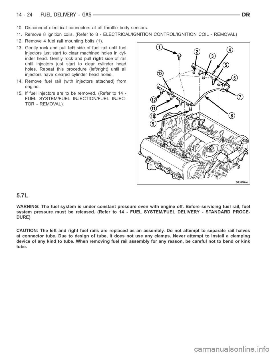
12. Remove 4 fuel rail mounting bolts (1).
13. Gently rock and pullleftside of fuel rail until fuel
injectors just start to clear machined holes in cyl-
inder head. Gently rock and pullrightside of rail
until injectors just start to clear cylinder head
holes. Repeat this procedure (left/right) until all
injectors have cleared cylinder head holes.
14. Remove fuel rail (with injectors attached) from
engine.
15. If fuel injectors are to be removed, (Refer to 14 -
FUEL SYSTEM/FUEL INJECTION/FUEL INJEC-
TOR - REMOVAL).
5.7L
WARNING: The fuel system is under constant pressure even with engine off. Before servicing fuel rail, fuel
system pressure must be released. (Refer to 14 - FUEL SYSTEM/FUEL DELIVERY- STANDARD PROCE-
DURE)
CAUTION: The left and right fuel rails are replaced as an assembly. Do not attempt to separate rail halves
at connector tube. Due to design of tube, it does not use any clamps. Never attempt to install a clamping
device of any kind to tube. When removing fuel rail assembly for any reason,be careful not to bend or kink
tube.
Page 2262 of 5267
1. Remove fuel tank filler tube cap.
2. Perform fuel system pressure release procedure.
(Refer to 14 - FUEL SYSTEM/FUEL DELIVERY -
STANDARD PROCEDURE)
3. Remove negative battery cable at battery.
4. Remove flex tube (air cleaner housing to engine).
5. Remove air resonator box at throttle body.
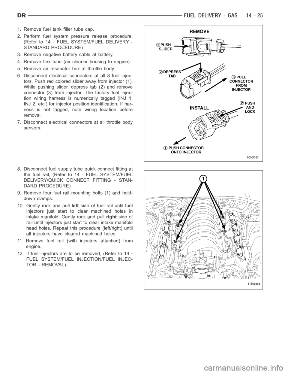
6. Disconnect electrical connectors at all 8 fuel injec-
tors. Push red colored slider away from injector (1).
While pushing slider, depress tab (2) and remove
connector (3) from injector. The factory fuel injec-
tion wiring harness is numerically tagged (INJ 1,
INJ 2, etc.) for injector position identification. If har-
ness is not tagged, note wiring location before
removal.
7. Disconnect electrical connectors at all throttle body
sensors.
8. Disconnect fuel supply tube quick connect fitting at
the fuel rail, (Refer to14 - FUEL SYSTEM/FUEL
DELIVERY/QUICK CONNECT FITTING - STAN-
DARD PROCEDURE).
9. Remove four fuel rail mounting bolts (1) and hold-
down clamps.
10. Gently rock and pullleftside of fuel rail until fuel
injectors just start to clear machined holes in
intake manifold. Gently rock and pullrightside of
rail until injectors just start to clear intake manifold
head holes. Repeat this procedure (left/right) until
all injectors have cleared machined holes.
11. Remove fuel rail (with injectors attached) from
engine.
12. If fuel injectors are to be removed, (Refer to 14 -
FUEL SYSTEM/FUEL INJECTION/FUEL INJEC-
TOR - REMOVAL).
Page 2281 of 5267
page page
PEDAL - ACCELERATOR
REMOVAL .................................... 46
INSTALLATION ............................... 46
SENSOR-ACCELERATOR PEDAL POSITION
DESCRIPTION ................................ 47
OPERATION .................................. 47
REMOVAL .................................... 47
INSTALLATION ............................... 48
SENSOR-CRANKSHAFT POSITION
DESCRIPTION
3.7L V-6 .................................... 49
4.7L V-8 .................................... 49
5.7L V-8 .................................... 50
OPERATION
3.7L V-6 .................................... 50
4.7L V-8 .................................... 51
5.7L V-8 .................................... 51
REMOVAL
3.7L V-6 .................................... 52
4.7L V-8 .................................... 52
5.7L V-8 .................................... 53
8.3L - SRT-10 ............................... 53
INSTALLATION
3.7L V-6 .................................... 54
4.7L V-8 .................................... 55
5.7L V-8 .................................... 55
8.3L - SRT-10 ............................... 55
INJECTOR - FUEL
DESCRIPTION ................................ 56
OPERATION
FUEL INJECTOR ............................ 56
PCM OUTPUT .............................. 56
REMOVAL
3.7/4.7/ 5.7L ................................ 57
8.3L - SRT-10 ............................... 57
INSTALLATION
3.7/ 4.7/ 5.7L ............................... 60
8.3L - SRT-10 ............................... 60
RELAY - FUEL PUMP
DESCRIPTION ................................ 61
OPERATION .................................. 61
REMOVAL .................................... 61
INSTALLATION ............................... 61
MOTOR-IAC
DESCRIPTION
3.7L, 4.7L, 5.7L ............................. 62
8.3L - SRT-10 ............................... 63
OPERATION
3.7L V-6/4.7L V-8 ............................ 63
REMOVAL
3.7L V-6 .................................... 644.7L V-8 .................................... 65
5.7L V-8 .................................... 65
8.3L - SRT-10 ............................... 65
INSTALLATION
3.7L V-6 .................................... 66
4.7L V-8 .................................... 66
5.7L V-8 .................................... 66
8.3L - SRT-10 ............................... 67
SENSOR - INLET AIR TEMPERATURE
REMOVAL — 8.3L ............................. 68
INSTALLATION ............................... 68
SENSOR-INTAKE AIR TEMPERATURE
DESCRIPTION
3.7L V-6 .................................... 69
4.7L V-8 .................................... 69
5.7L V-8 .................................... 70
OPERATION .................................. 70
REMOVAL
3.7L V-6 .................................... 71
4.7L V-8 .................................... 72
5.7L V-8 .................................... 73
INSTALLATION
3.7L V-6 .................................... 74
4.7L V-8 .................................... 75
5.7L V-8 .................................... 75
SENSOR-MAP
DESCRIPTION
3.7L V-6 .................................... 76
4.7L V-8 .................................... 76
5.7L V-8 .................................... 77
8.3L - SRT-10 ............................... 77
OPERATION .................................. 77
REMOVAL
3.7L V-6 .................................... 79
4.7L V-8 .................................... 80
5.7L V-8 .................................... 80
8.3 L - SRT-10 .............................. 81
INSTALLATION
3.7L V-6 .................................... 81
4.7L V-8 .................................... 82
5.7L V-8 .................................... 83
8.3L - SRT-10 ............................... 83
SENSOR - OXYGEN
DESCRIPTION ................................ 84
REMOVAL .................................... 84
INSTALLATION ............................... 85
SWITCH-PTO
DESCRIPTION ................................ 86
OPERATION .................................. 86
THROTTLE BODY
DESCRIPTION ................................ 87
Page 2294 of 5267
Battery voltage (12 volts +) is supplied to the injectors through the ASD relay. The ASD relay will shut-down the 12
volt power source to the fuel injectors if the PCM senses the ignition is on,but the engine is not running. This
occurs after the engine has not been running for approximately 1.8 seconds.
The PCM determines injector on-time (pulse width) based on various inputs.
REMOVAL
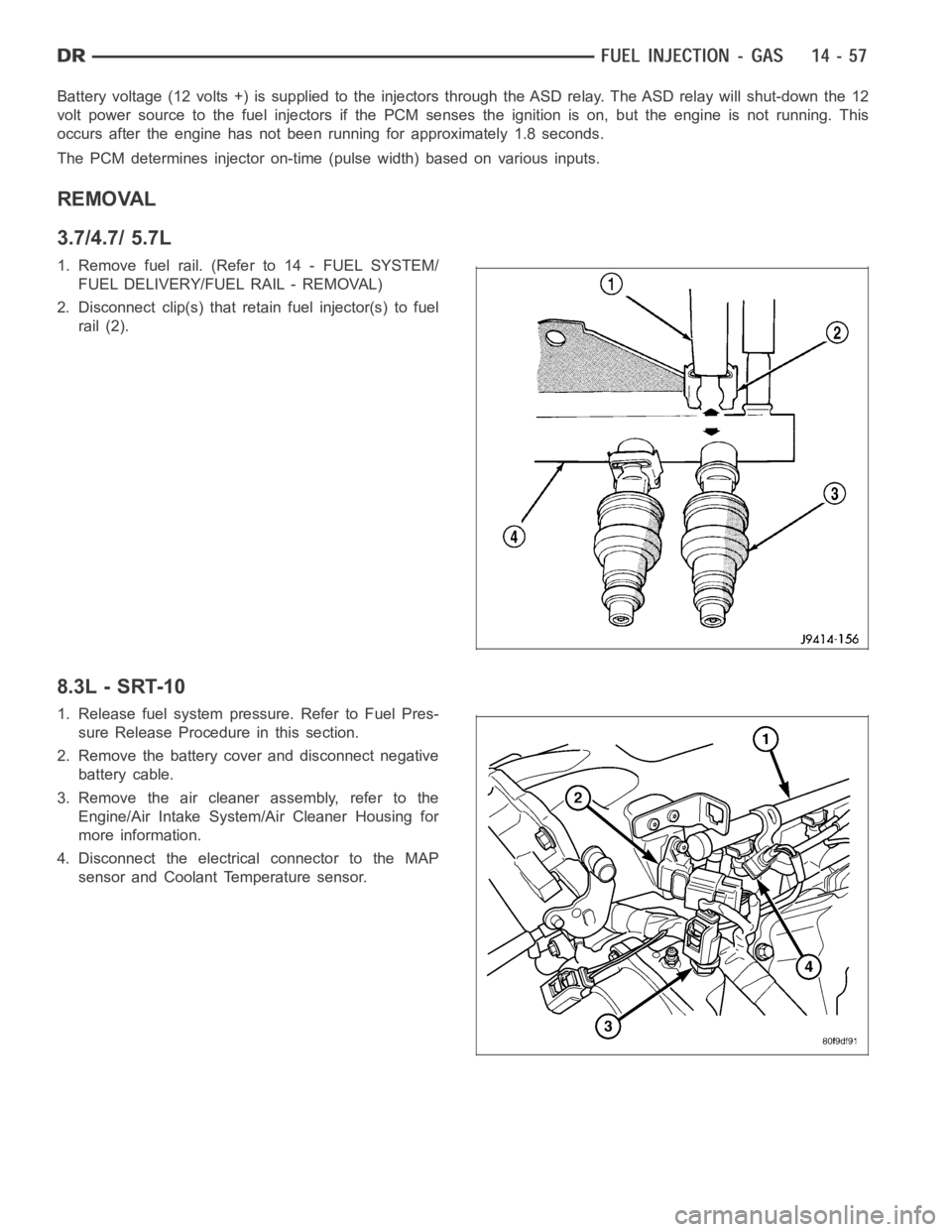
3.7/4.7/ 5.7L
1. Remove fuel rail. (Refer to 14 - FUEL SYSTEM/
FUEL DELIVERY/FUEL RAIL - REMOVAL)
2. Disconnect clip(s) that retain fuel injector(s) to fuel
rail (2).
8.3L - SRT-10
1. Release fuel system pressure. Refer to Fuel Pres-
sure Release Procedure in this section.
2. Remove the battery cover and disconnect negative
battery cable.
3. Remove the air cleaner assembly, refer to the
Engine/Air Intake System/Air Cleaner Housing for
more information.
4. Disconnect the electrical connector to the MAP
sensor and Coolant Temperature sensor.
Page 2324 of 5267
THROTTLE BODY
DESCRIPTION
The throttle body is located on the intake manifold. Fuel does not enter theintake manifold through the throttle body.
Fuel is sprayed into the manifold by the fuel injectors.
OPERATION
Filtered air from the air cleaner enters the intake manifold through the throttle body. The throttle body contains an air
control passage controlled by an Idle Air Control (IAC) motor. The air control passage is used to supply air for idle
conditions. A throttle valve (plate) is used to supply air for above idle conditions.
5.7L V-8 Engine:
The throttle body on the 5.7L engine is an electrically controlled unit. A mechanical cable is not used to connect the
throttle body to the accelerator pedal. The Accelerator Pedal Position Sensor (APPS) along with inputs from other
sensors sets the throttle blade to pre-determined positions.
Except 5.7L V-8 Engine:
Certain sensors are attached to the throttle body. The accelerator pedal cable, speed control cable and transmission
control cable (when equipped) are connected to the throttle body linkage arm.
A (factory adjusted) set screw is usedto mechanically limit the position of the throttle body throttle plate.Never
attempt to adjust the engine idle speed using this screw.All idle speed functions are controlled by the PCM.
REMOVAL
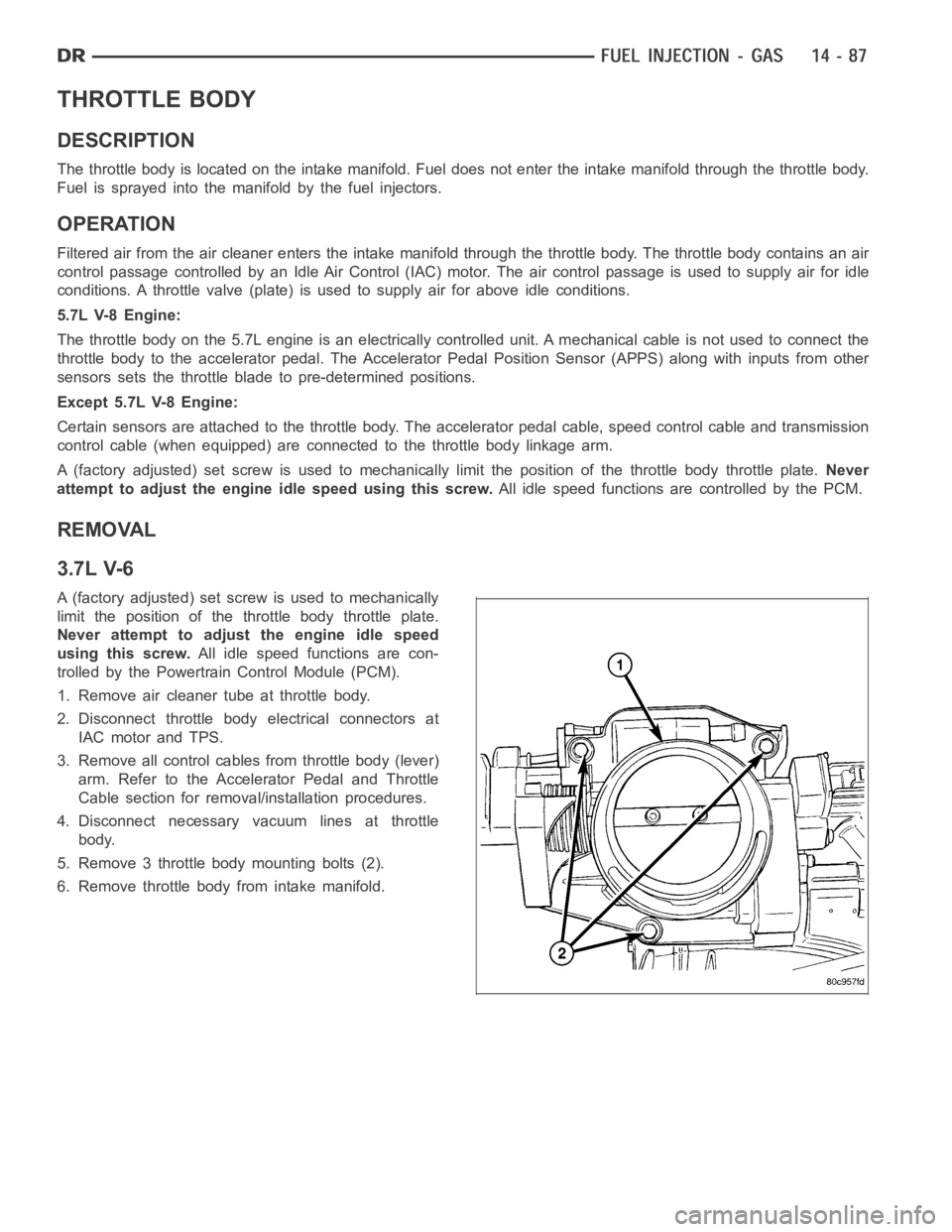
3.7L V-6
A (factory adjusted) set screw is used to mechanically
limit the position of the throttle body throttle plate.
Never attempt to adjust the engine idle speed
using this screw.All idle speed functions are con-
trolled by the Powertrain Control Module (PCM).
1. Remove air cleaner tube at throttle body.
2. Disconnect throttle body electrical connectors at
IAC motor and TPS.
3. Remove all control cables from throttle body (lever)
arm. Refer to the Accelerator Pedal and Throttle
Cable section for removal/installation procedures.
4. Disconnect necessary vacuum lines at throttle
body.
5. Remove 3 throttle body mounting bolts (2).
6. Remove throttle body from intake manifold.