Page 1879 of 5267

PA N - E N G I N E O I L
REMOVAL
1. Disconnect the negative battery cable.
2. Install engine support fixture special tool # 8534.Do not raise engine at this time.
3.For 2WD vehicles,Remove both engine mount to frame through bolts.
4.For 4WD vehicles,Loosen both left and right side engine mount bracket to mount bolts, and remove the lower
bolt on each side. The upper hole in the engine bracket is slotted.
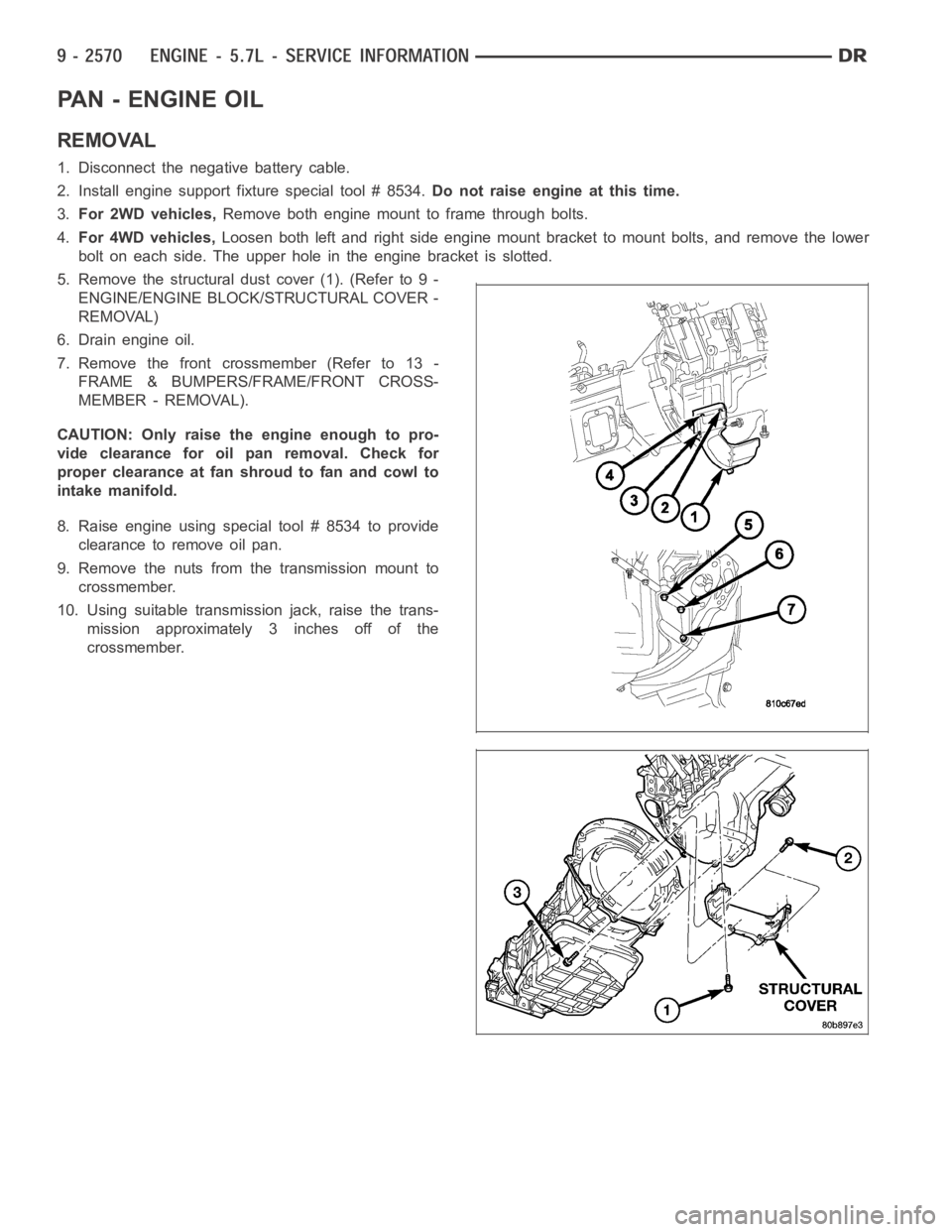
5. Remove the structural dust cover (1). (Refer to 9 -
ENGINE/ENGINE BLOCK/STRUCTURAL COVER -
REMOVAL)
6. Drain engine oil.
7. Remove the front crossmember (Refer to 13 -
FRAME & BUMPERS/FRAME/FRONT CROSS-
MEMBER - REMOVAL).
CAUTION: Only raise the engine enough to pro-
vide clearance for oil pan removal. Check for
proper clearance at fan shroud to fan and cowl to
intake manifold.
8. Raise engine using special tool # 8534 to provide
clearance to remove oil pan.
9. Remove the nuts from the transmission mount to
crossmember.
10. Using suitable transmission jack, raise the trans-
mission approximately 3 inches off of the
crossmember.
Page 1881 of 5267

2. Apply MoparEngine RTV at the 4 T- joints.
NOTE: When the oil pan is removed, a new inte-
gral windage tray and gasket assembly must be
installed. The old gasket cannot be reused.
3. Install a new integral windage tray and gasket.
4. Reinstall the oil pump pickup tube with new o-ring.
Tighten tube to pump fasteners to 28 Nꞏm (250 in.
lbs.).
NOTE: The double ended oil pan studs must be
installed in the same location that they were
removed from.
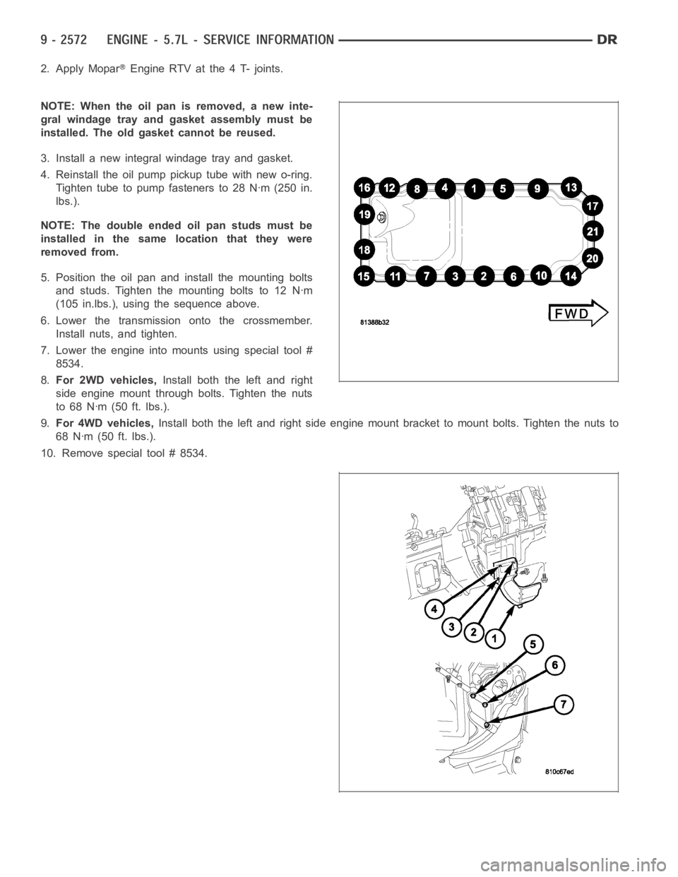
5. Position the oil pan and install the mounting bolts
and studs. Tighten the mounting bolts to 12 Nꞏm
(105 in.lbs.), using the sequence above.
6. Lower the transmission onto the crossmember.
Install nuts, and tighten.
7. Lower the engine into mounts using special tool #
8534.
8.For 2WD vehicles,Install both the left and right
side engine mount through bolts. Tighten the nuts
to 68 Nꞏm (50 ft. lbs.).
9.For 4WD vehicles,Install both the left and right side engine mount bracket to mount bolts. Tighten the nuts to
68 Nꞏm (50 ft. lbs.).
10. Remove special tool # 8534.
Page 2218 of 5267
TORQUE
TORQUE SPECIFICATIONS
DESCRIPTION Nꞏm Ft. Lbs.
Cab mount bolts 81 60
Cargo box bolts 108 80
Front crossmember bolts - 2WD (light duty only) 61 45
Front crossmember bolts - 2WD (heavy duty only) 75 55
Front crossmember bolts - 4WD (light duty only) 102 75
Front skid plate bolts 34 25
Lower bumper support bracket bolt 54 40
Radiator crossmember bolts - lower 28 21
Radiator crossmember bolts - upper 28 21
Rear crossmember (light duty only) 102 75
Rear crossmember (heavy duty only) 115 85
Rear spring shackle bolts 163 120
Sparetirewinchbolts 41 30
Trailer hitch reinforcement bracket bolt 170 125
Transfercase skid plate bolts 34 25
Transercase skid plate crossmember bolts 34 25
Transmission mount to crossmember nuts 54 40
Page 2220 of 5267
3. On the 2WD models, remove the bolts (2) and
remove the crossmember (1).
CAUTION: Do not use any flame or plasma cutting
equipment to cut the frame in this procedure. This
is due to the inaccurate nature of the cut-line and
the fact that the high temperatures achieved dur-
ing flame or plasma cutting will change the metal
characteristics and may weaken the frame and/or
repair location.
4. On SRT-10 vehicles, remove the welds using a
grinder or equivalent.
5. On the 4WD models, remove the bolts (1) and
remove the crossmember (2).
Page 2221 of 5267
INSTALLATION
1. Install the crossmember (1).
2. Install the bolts (2);
On light duty 2WD vehicles, tighten the bolts to
61 Nꞏm (45 ft. lbs.).
On heavy duty 2WD vehicles, tighten the bolts to
75 Nꞏm (55 ft. lbs.).
3. On 4WD models, install the crossmember (2).
4. Install the bolts (1) and tighten to 102 Nꞏm (75 ft.
lbs.).
5. Remove all OEM e-coat within 51 mm (2.0 in.) of
the weld on both the crossmember and the frame.
CAUTION: Shield the surrounding area and com-
ponents from exposure to the welding spatter and
heat.
6. Using the Weld Process Specifications table (Refer
to 13 - FRAME & BUMPERS/FRAME - SPECIFI-
CATIONS - WELDING), apply new welds to the
SRT-10 crossmember.
NOTE: Any burned surface coatings will need to
be removed prior to application of corrosion pre-
ventative coatings.
7. Dress the welded area and apply corrosion resis-
tant coatings.
a. Apply etch-primer to the repair area.
b. Apply a durable top coat to the outside of the repair area.
Page 2228 of 5267
3. Support the transmission (1) with a transmission
jack (2) or suitable lifting device.
4.2WD Vehicles- Remove the transmission mount
nuts (3).
5. Remove the bolts and remove the crossmember
(2).
6.4WD Vehicles- Remove the transmission mount
nuts (5).
7. Remove the bolts (3) and remove the crossmem-
ber (4).
Page 2525 of 5267
REMOVAL
1. With vehicle in neutral, position vehicle on hoist.
2. Disconnect battery negative cable.
3. Remove shift boot bezel screws and slide boot
upward on shift lever extension.
4. Remove shift lever extension from the shift tower
and lever assembly.
5. Remove 4WD shift boot if equipped.
6. Remove skid plate, if equipped.
7. Remove drain plug (1) from transmission (2) and
drain fluid.
8. Mark transmission flange (1) and propeller shaft (2)
for installation reference before removing propeller
shaft. If 4x4 equipped mark transfer case and front
propeller shaft before removing shaft.
Page 2593 of 5267
4. Remove fill plug (1) from side of transmission (2).
5. Fill transmission even with the bottom of the fill
hole.
6. Install fill plug and tighten to 50 Nꞏm (37 ft. lbs.).
REMOVAL
1. With vehicle in neutral, position vehicle on hoist.
2. Disconnect battery negative cable.
3. Remove shift boot bezel screws and slide boot
upward on shift lever extension.
4. Remove shift lever extension from the shift tower
and lever assembly.
5. Remove 4WD shift boot if equipped and remove
floor console.
6. Remove skid plate, if equipped.
7. Remove drain plug (1) from rear housing (2) and
drain fluid.
8. Mark propeller shaft/shafts and companion flange
yoke/yokes for installation reference and remove
propeller shaft/shafts.
9. Disconnect harness from clips on transmission
housing.
10. Remove transfer case linkage if equipped.
11. Remove transfer case mounting nuts and remove
transfer case if equipped.
12. Remove slave cylinder (2) mounting nut (1) and
remove cylinder.