Page 1518 of 5267
7. Remove the master cylinder and booster assembly (Refer to 5 - BRAKES/HYDRAULIC/MECHANICAL/POWER
BRAKE BOOSTER - REMOVAL).
8. Remove the cylinder head cover (Refer to 9 - ENGINE/CYLINDER HEAD/CYLINDER HEAD COVER(S) -
REMOVAL).
9. Remove the fan shroud and fan blade assembly
(Refer to 7 - COOLING/ENGINE/RADIATOR FAN -
REMOVAL).
10. Remove accessory drive belt (Refer to 7 - COOL-
ING/ACCESSORY DRIVE/DRIVE BELTS -
REMOVAL).
11. Remove the power steering pump and set aside.
12. Rotate the crankshaft until the damper timing
mark is aligned with TDC indicator mark (2).
13. Verify the V6 mark on the camshaft sprocket is at the 12 o’clock position. Rotate the crankshaft one turn if
necessary.
14. Remove the crankshaft damper (Refer to 9 - ENGINE/ENGINE BLOCK/VIBRATION DAMPER - REMOVAL).
15. Remove the timing chain cover (Refer to 9 - ENGINE/VALVE TIMING/TIMINGBELT / CHAIN COVER(S) -
REMOVAL).
Page 1519 of 5267
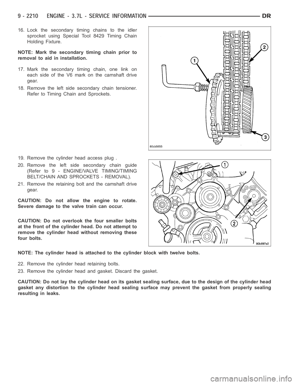
16. Lock the secondary timing chains to the idler
sprocket using Special Tool 8429 Timing Chain
Holding Fixture.
NOTE: Mark the secondary timing chain prior to
removal to aid in installation.
17. Mark the secondary timing chain, one link on
each side of the V6 mark on the camshaft drive
gear.
18. Remove the left side secondary chain tensioner.
Refer to Timing Chain and Sprockets.
19. Remove the cylinder head access plug .
20. Remove the left side secondary chain guide
(Refer to 9 - ENGINE/VALVE TIMING/TIMING
BELT/CHAIN AND SPROCKETS - REMOVAL).
21. Remove the retaining bolt and the camshaft drive
gear.
CAUTION: Do not allow the engine to rotate.
Severe damage to the valve train can occur.
CAUTION: Do not overlook the four smaller bolts
at the front of the cylinder head. Do not attempt to
remove the cylinder head without removing these
four bolts.
NOTE: The cylinder head is attached to the cylinder block with twelve bolts.
22. Remove the cylinder head retaining bolts.
23. Remove the cylinder head and gasket. Discard the gasket.
CAUTION: Do not lay the cylinder head on its gasket sealing surface, due to the design of the cylinder head
gasket any distortion to the cylinder head sealing surface may prevent thegasket from properly sealing
resulting in leaks.
Page 1521 of 5267
2. Position the new cylinder head gasket on the locat-
ing dowels.
CAUTION: When installing cylinder head, use care
not damage the tensioner arm or the guide arm.
3. Position the cylinder head onto the cylinder block.
Make sure the cylinder head seats fully over the
locating dowels.
NOTE: The four smaller cylinder head mounting
bolts require sealant to be added to them before
installing. Failure to do so may cause leaks.
4. Lubricate the cylinder head bolt threads with clean
engine oil and install the eight M11 bolts.
5. Coat the four M8 cylinder head bolts withMopar
Lock and Seal Adhesivethen install the bolts.
NOTE: The cylinder head bolts are tightened using
an angle torque procedure, however, the bolts are
not a torque-to-yield design.
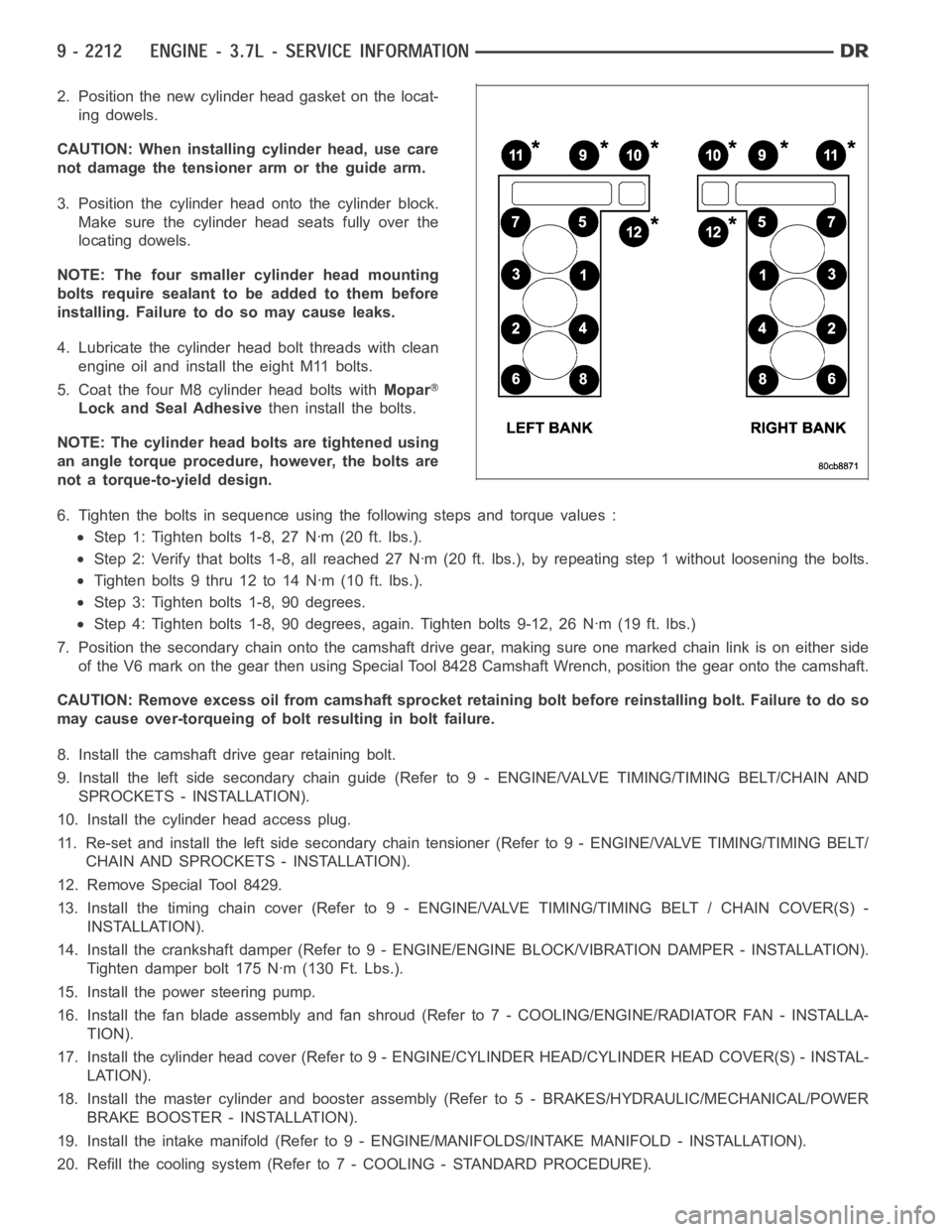
6. Tighten the bolts in sequence using the following steps and torque values:
Step 1: Tighten bolts 1-8, 27 Nꞏm (20 ft. lbs.).
Step 2: Verify that bolts 1-8, all reached 27 Nꞏm (20 ft. lbs.), by repeatingstep 1 without loosening the bolts.
Tightenbolts9thru12to14Nꞏm(10ft.lbs.).
Step 3: Tighten bolts 1-8, 90 degrees.
Step 4: Tighten bolts 1-8, 90 degrees, again. Tighten bolts 9-12, 26 Nꞏm (19ft. lbs.)
7. Position the secondary chain onto the camshaft drive gear, making sure one marked chain link is on either side
of the V6 mark on the gear then using Special Tool 8428 Camshaft Wrench, position the gear onto the camshaft.
CAUTION: Remove excess oil from camshaft sprocket retaining bolt before reinstalling bolt. Failure to do so
may cause over-torqueing of bolt resulting in bolt failure.
8. Install the camshaft drive gear retaining bolt.
9. Install the left side secondary chain guide (Refer to 9 - ENGINE/VALVE TIMING/TIMING BELT/CHAIN AND
SPROCKETS - INSTALLATION).
10. Install the cylinder head access plug.
11. Re-set and install the left side secondary chain tensioner (Refer to 9 -ENGINE/VALVE TIMING/TIMING BELT/
CHAIN AND SPROCKETS - INSTALLATION).
12. Remove Special Tool 8429.
13. Install the timing chain cover (Refer to 9 - ENGINE/VALVE TIMING/TIMING BELT / CHAIN COVER(S) -
INSTALLATION).
14. Install the crankshaft damper (Refer to 9 - ENGINE/ENGINE BLOCK/VIBRATION DAMPER - INSTALLATION).
Tighten damper bolt 175 Nꞏm (130 Ft. Lbs.).
15. Install the power steering pump.
16. Install the fan blade assembly and fan shroud (Refer to 7 - COOLING/ENGINE/RADIATOR FAN - INSTALLA-
TION).
17. Install the cylinder head cover (Refer to 9 - ENGINE/CYLINDER HEAD/CYLINDER HEAD COVER(S) - INSTAL-
LATION).
18. Install the master cylinder and booster assembly (Refer to 5 - BRAKES/HYDRAULIC/MECHANICAL/POWER
BRAKE BOOSTER - INSTALLATION).
19. Install the intake manifold (Refer to 9 - ENGINE/MANIFOLDS/INTAKE MANIFOLD - INSTALLATION).
20. Refill the cooling system (Refer to 7 - COOLING - STANDARD PROCEDURE).
Page 1522 of 5267
21. Raise the vehicle.
22. Install the exhaust pipe onto the left exhaust manifold.
23. Lower the vehicle.
24. Connect the negative cable to the battery.
25. Start the engine and check for leaks.
Page 1523 of 5267
CAMSHAFT
DESCRIPTION
The camshafts consist of powdered metal steel lobes which are sinter-bonded to a steel tube. Four bearing journals
are machined into the camshaft. Camshaft end play is controlled by two thrust walls that border the nose piece
journal.
REMOVAL
CAUTION: When the timing chain is removed and the cylinder heads are still installed, DO NOT forcefully
rotate the camshafts or crankshaft independently of each other. Severe valve and/or piston damage can
occur.
CAUTION: When removing the cam sprocket, timing chains or camshaft, Failure to use Special Tool 8379
will result in hydraulic tensioner ratchet over extension, requiring timing chain cover removal to reset the
tensioner ratchet.
1. Remove cylinder head cover (Refer to 9 - ENGINE/CYLINDER HEAD/CYLINDERHEAD COVER(S) -
REMOVAL).
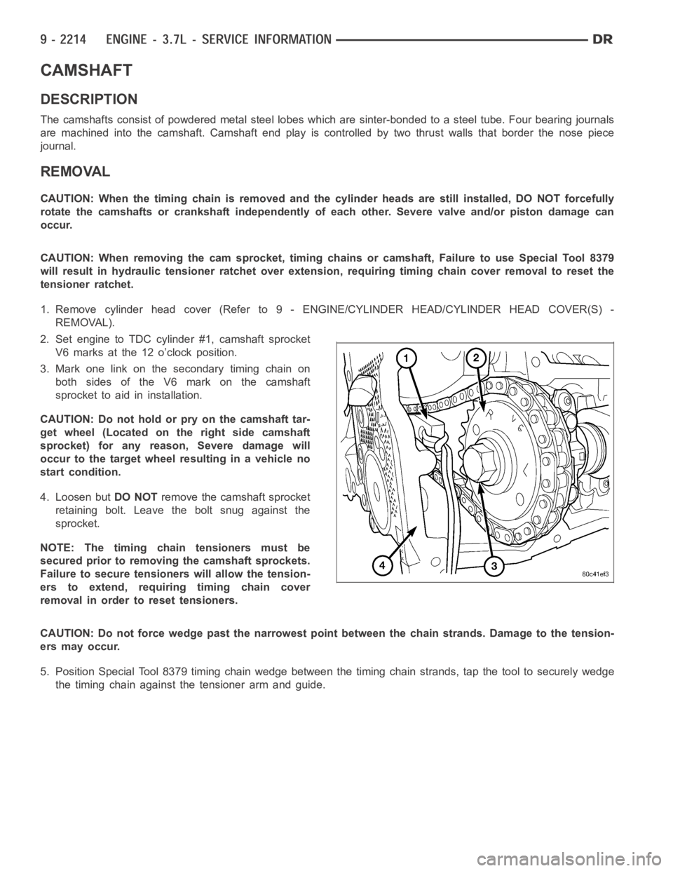
2. Set engine to TDC cylinder #1, camshaft sprocket
V6 marks at the 12 o’clock position.
3. Mark one link on the secondary timing chain on
both sides of the V6 mark on the camshaft
sprocket to aid in installation.
CAUTION: Do not hold or pry on the camshaft tar-
get wheel (Located on the right side camshaft
sprocket) for any reason, Severe damage will
occur to the target wheel resulting in a vehicle no
start condition.
4. Loosen butDO NOTremove the camshaft sprocket
retaining bolt. Leave the bolt snug against the
sprocket.
NOTE: The timing chain tensioners must be
secured prior to removing the camshaft sprockets.
Failure to secure tensioners will allow the tension-
erstoextend,requiringtimingchaincover
removal in order to reset tensioners.
CAUTION: Do not force wedge past the narrowest point between the chain strands. Damage to the tension-
ers may occur.
5. Position Special Tool 8379 timing chain wedge between the timing chain strands, tap the tool to securely wedge
the timing chain against the tensioner arm and guide.
Page 1524 of 5267
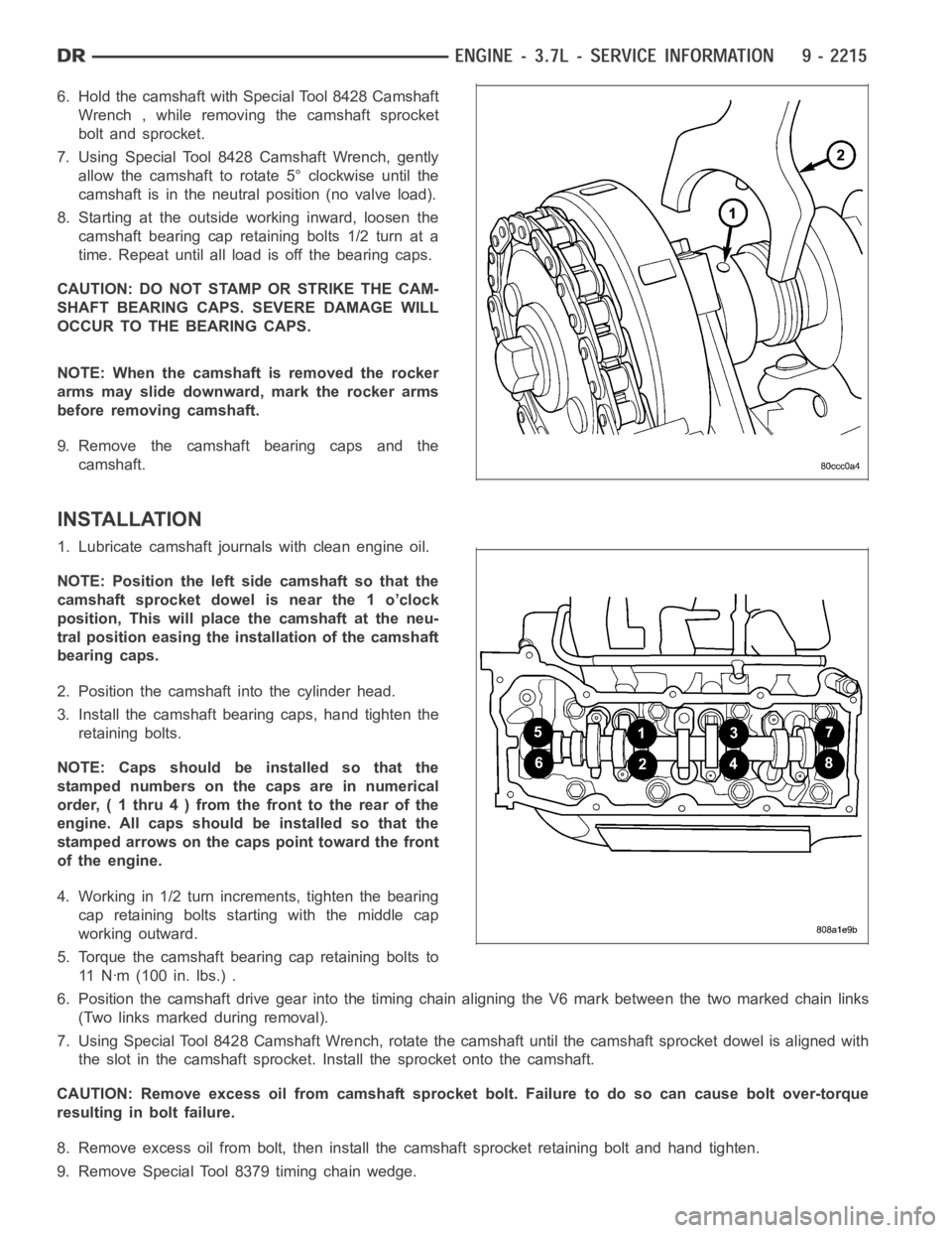
6. Hold the camshaft with Special Tool 8428 Camshaft
Wrench , while removing the camshaft sprocket
bolt and sprocket.
7. Using Special Tool 8428 Camshaft Wrench, gently
allow the camshaft to rotate 5° clockwise until the
camshaft is in the neutral position (no valve load).
8. Starting at the outside working inward, loosen the
camshaft bearing cap retaining bolts 1/2 turn at a
time. Repeat until all load is off the bearing caps.
CAUTION: DO NOT STAMP OR STRIKE THE CAM-
SHAFT BEARING CAPS. SEVERE DAMAGE WILL
OCCUR TO THE BEARING CAPS.
NOTE: When the camshaft is removed the rocker
arms may slide downward, mark the rocker arms
before removing camshaft.
9. Remove the camshaft bearing caps and the
camshaft.
INSTALLATION
1. Lubricate camshaft journals with clean engine oil.
NOTE: Position the left side camshaft so that the
camshaft sprocket dowel is near the 1 o’clock
position, This will place the camshaft at the neu-
tral position easing the installation of the camshaft
bearing caps.
2. Position the camshaft into the cylinder head.
3. Install the camshaft bearing caps, hand tighten the
retaining bolts.
NOTE: Caps should be installed so that the
stamped numbers on the caps are in numerical
order, ( 1 thru 4 ) from the front to the rear of the
engine. All caps should be installed so that the
stamped arrows on the caps point toward the front
of the engine.
4. Working in 1/2 turn increments, tighten the bearing
cap retaining bolts starting with the middle cap
working outward.
5. Torque the camshaft bearing cap retaining bolts to
11 N ꞏm ( 1 0 0 i n . l b s . ) .
6. Position the camshaft drive gear into the timing chain aligning the V6 mark between the two marked chain links
(Two links marked during removal).
7. Using Special Tool 8428 Camshaft Wrench, rotate the camshaft until the camshaft sprocket dowel is aligned with
the slot in the camshaft sprocket. Install the sprocket onto the camshaft.
CAUTION: Remove excess oil from camshaft sprocket bolt. Failure to do so can cause bolt over-torque
resulting in bolt failure.
8. Remove excess oil from bolt, then install the camshaft sprocket retaining bolt and hand tighten.
9. Remove Special Tool 8379 timing chain wedge.
Page 1525 of 5267
10. Using Special Tool 6958 spanner wrench with adapter pins 8346, torque the camshaft sprocket retaining bolt to
122Nꞏm(90ft.lbs.).
11. Install the cylinder head cover (Refer to 9 - ENGINE/CYLINDER HEAD/CYLINDER HEAD COVER(S) - INSTAL-
LATION).
Page 1529 of 5267
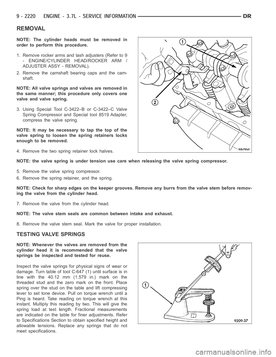
REMOVAL
NOTE: The cylinder heads must be removed in
order to perform this procedure.
1. Remove rocker arms and lash adjusters (Refer to 9
- ENGINE/CYLINDER HEAD/ROCKER ARM /
ADJUSTER ASSY - REMOVAL).
2. Remove the camshaft bearing caps and the cam-
shaft.
NOTE: All valve springs and valves are removed in
the same manner; this procedure only covers one
valve and valve spring.
3. Using Special Tool C-3422–B or C-3422–C Valve
Spring Compressor and Special tool 8519 Adapter,
compress the valve spring.
NOTE: It may be necessary to tap the top of the
valve spring to loosen the spring retainers locks
enough to be removed.
4. Remove the two spring retainer lock halves.
NOTE: the valve spring is under tension use care when releasing the valve spring compressor.
5. Remove the valve spring compressor.
6. Remove the spring retainer, and the spring.
NOTE: Check for sharp edges on the keeper grooves. Remove any burrs from thevalvestembeforeremov-
ing the valve from the cylinder head.
7. Remove the valve from the cylinder head.
NOTE: The valve stem seals are common between intake and exhaust.
8. Remove the valve stem seal. Mark the valve for proper installation.
TESTING VALVE SPRINGS
NOTE: Whenever the valves are removed from the
cylinder head it is recommended that the valve
springs be inspected and tested for reuse.
Inspect the valve springs for physical signs of wear or
damage. Turn table of tool C-647 (1) until surface is in
line with the 40.12 mm (1.579 in.) mark on the
threaded stud and the zero mark on the front. Place
spring over the stud on the table and lift compressing
lever to set tone device. Pull on torque wrench until a
Ping is heard. Take reading on torque wrench at this
instant. Multiply this reading by two. This will give the
spring load at test length. Fractional measurements
are indicated on the table for finer adjustments. Refer
to Specifications Section to obtain specified height and
allowable tensions. Replace any springs that do not
meet specifications.