2006 DODGE RAM SRT-10 engine
[x] Cancel search: enginePage 1485 of 5267
NOTE: If this vehicle is equipped with an Electronic Throttle Control system, and the APP Sensors, PCM, or
Throttle Body Assembly have been replaced, use the scan tool to perform theETC RELEARN function.
14. If the indicator ball shows a leak present, perform the smoke test indicated in the previous test and identify the
leak and repair. Perform this verification test when the repair is complete.
Didtheindicatorballindicatethealeakispresent?
Ye s>>
Repeat the DTC test to identify the leak and repair.
No>>
Repair is complete.
5.POWERTRAIN VERIFICATION TEST 4
NOTE: 1. After completing the Powertrain Verification Test the Transmission Verification Test must be per-
formed.
NOTE: 2. If the PCM has been replaced and the correct VIN and mileage have notbeen programmed, a DTC
will set in the ABS Module, Airbag Module and the SKIM/SKREEM.
NOTE: 3. If the vehicle is equipped with a Sentry Key Remote Entry, Secret Key data must be updated. Refer
to the Service Information for the PCM, SKIM/SKREEM and the Transponder (ignition key) for programming
information. Using the scan tool, program the Secret Key information intothe PCM using the PCM replaced
function under the WCM menu.
NOTE: 4. If this vehicle is equipped with an Electronic Throttle Control system, and the APP Sensors, PCM,
or Throttle Body Assembly have been replaced, use the scan tool to perform the ETC RELEARN function.
NOTE: 5. When replacing an O2 Sensor, the PCM RAM memory must be cleared, either by disconnecting the
PCM C1 connector or momentarily disconnecting the Battery negative terminal.
6. The NGC learns the characteristics of each O2 heater element and these old values should be cleared when
installing a new O2 sensor. The customermay experience driveability issues if this is not performed.
7. Inspect the vehicle to make sure that all engine components are properlyinstalled and connected. Reassemble
and reconnect components as necessary.
8. Connect the scan tool to the data link connector.
9. Make sure the fuel tank has at least a quarter tank of fuel. Turn off all accessories.
10. If the Catalyst was replaced, with the scan tool go to the MiscellaneousMenu Option
Catalyst Replacedand
press enter.
11. If a Comprehensive Component DTC was repaired, perform steps 12 - 14. Ifa Major OBDII Monitor DTC was
repaired skip those steps and continue verification.
12. After the ignition has been off for at least 10 seconds, restart the vehicle and run 2 minutes.
13. With the scan tool, monitor the appropriate pre-test enabling conditions until all conditions have been met. Once
the conditions have been met, switch screen to the appropriate OBDII monitor, (Audible beeps when the monitor is
running).
14. If the repaired OBDII trouble code has reset or was seen in the monitor while on the road test, the repair is not
complete. Check for any related technical service bulletins or flash updates and return to Engine Electrical Diag-
nostic List.
15. If the conditions cannot be duplicated, erase all DTCs with the Scan tool.
16. If another DTC has set, return to the Engine Electrical Diagnostic Listand follow the path specified for that DTC.
Did the OBDII Monitor run successfully and has the Good Trip Counter changed to one or more?
Ye s>>
Repair is complete.
No>>
Check for any related Technical Service Bulletins and/or refer to the appropriate Diagnostic Procedure.
Page 1487 of 5267
page page
ENGINE - 3.7L - SERVICE INFORMATION
DESCRIPTION ............................. 2180
DIAGNOSIS AND TESTING
DIAGNOSIS AND TESTING - ENGINE
DIAGNOSIS - INTRODUCTION............. 2180
DIAGNOSIS AND TESTING - ENGINE
DIAGNOSIS - PERFORMANCE............. 2181
DIAGNOSIS AND TESTING - ENGINE
DIAGNOSIS - MECHANICAL............... 2183
DIAGNOSIS AND TESTING - ENGINE
DIAGNOSIS - LUBRICATION............... 2183
DIAGNOSIS AND TESTING - CYLINDER
COMPRESSION PRESSURE............... 2185
DIAGNOSIS AND TESTING - CYLINDER
COMBUSTION PRESSURE LEAKAGE...... 2185
STANDARD PROCEDURE
STANDARD PROCEDURE - REPAIR
DAMAGED OR WORN THREADS.......... 2186
STANDARD PROCEDURE - FORM-IN-
PLACE GASKETS AND SEALERS.......... 2186
STANDARD PROCEDURE - ENGINE
GASKET SURFACE PREPARATION........ 2187
REMOVAL ................................. 2188
INSTALLATION ............................. 2192
SPECIFICATIONS
SPECIFICATIONS - 3.7L ENGINE .......... 2195
TORQUE ................................. 2199
SPECIAL TOOLS ........................... 2202
ELEMENT - AIR CLEANER
REMOVAL ................................. 2206
INSTALLATION ............................. 2207
HEAD-CYLINDER-LEFT
DIAGNOSIS AND TESTING - CYLINDER HEAD
GASKET . . ............................... 2208
REMOVAL ................................. 2208
INSTALLATION ............................. 2211
CAMSHAFT
DESCRIPTION ............................. 2214
REMOVAL ................................. 2214
INSTALLATION ............................. 2215
COVER-CYLINDER HEAD
DESCRIPTION ............................. 2217
REMOVAL ................................. 2217
INSTALLATION ............................. 2218
VALVES & SEATS - INTAKE/EXHAUST
DESCRIPTION ............................. 2219
STANDARD PROCEDURE - REFACING ....... 2219
REMOVAL ................................. 2220
INSTALLATION ............................. 2221
ARM-VALVE ROCKER
DESCRIPTION ............................. 2222REMOVAL ................................. 2222
INSTALLATION ............................. 2222
SEALS-VALVE GUIDE
DESCRIPTION ............................. 2224
SPRINGS-VALVE
DESCRIPTION ............................. 2225
REMOVAL ................................. 2225
INSTALLATION ............................. 2225
HEAD-CYLINDER-RIGHT
DIAGNOSIS AND TESTING - HYDRAULIC
LASH ADJUSTER ......................... 2227
REMOVAL
REMOVAL RIGHT CYLINDER HEAD ........ 2227
INSTALLATION
INSTALLATION RIGHT CYLINDER HEAD . . . 2230
CAMSHAFT
DESCRIPTION ............................. 2234
REMOVAL ................................. 2234
INSTALLATION ............................. 2237
COVER - CYLINDER HEAD
REMOVAL ................................. 2239
INSTALLATION ............................. 2239
ROCKER ARM - VALVE
DESCRIPTION ............................. 2240
REMOVAL ................................. 2240
SEALS - VALVE GUIDE
DESCRIPTION ............................. 2241
SPRINGS - VALVE
DESCRIPTION ............................. 2242
REMOVAL ................................. 2242
INSTALLATION ............................. 2242
BLOCK-ENGINE
DESCRIPTION ............................. 2244
STANDARD PROCEDURE - CYLINDER BORE
HONING ................................. 2244
CLEANING ................................. 2244
INSPECTION............................... 2245
CRANKSHAFT
DESCRIPTION ............................. 2246
REMOVAL ................................. 2247
INSPECTION............................... 2248
INSTALLATION ............................. 2248
BEARINGS-CRANKSHAFT MAIN
STANDARD PROCEDURE
MAIN BEARING FITTING.................. 2251
SEAL-CRANKSHAFT OIL-FRONT
REMOVAL ................................. 2253
INSTALLATION ............................. 2254
SEAL-CRANKSHAFT OIL-REAR
DIAGNOSIS AND TESTING - REAR SEAL
AREA LEAKS ............................. 2255
Page 1488 of 5267
REMOVAL ................................. 2255
INSTALLATION ............................. 2256
PLATE-FLEX
REMOVAL ................................. 2257
INSTALLATION ............................. 2257
ROD-PISTON AND CONNECTING
DESCRIPTION ............................. 2258
STANDARD PROCEDURE
CONNECTING ROD BEARING FITTING .... 2258
STANDARD PROCEDURE - PISTON
FITTING.................................. 2261
REMOVAL ................................. 2262
CLEANING ................................. 2262
INSPECTION ............................... 2262
INSTALLATION ............................. 2263
RINGS-PISTON
STANDARD PROCEDURE - PISTON RING
FITTING .................................. 2265
DAMPER-CRANKSHAFT
REMOVAL ................................. 2268
INSTALLATION ............................. 2269
COVER-STRUCTURAL
DESCRIPTION ............................. 2270
OPERATION ............................... 2270
REMOVAL ................................. 2270
INSTALLATION ............................. 2270
MOUNT-FRONT
REMOVAL ................................. 2271
INSTALLATION ............................. 2273
MOUNT-REAR
REMOVAL ................................. 2275
INSTALLATION ............................. 2275
LUBRICATION
DESCRIPTION ............................. 2276
OPERATION ............................... 2276
DIAGNOSIS AND TESTING
DIAGNOSIS AND TESTING - ENGINE OIL
LEAK.................................... 2278
DIAGNOSIS AND TESTING - CHECKING
ENGINE OIL PRESSURE.................. 2279
DIAGNOSIS AND TESTING - REAR SEAL
AREA LEAKS............................. 2279
PAN-ENGINE OIL
DESCRIPTION ............................. 2280
REMOVAL ................................. 2281
CLEANING ................................. 2282
INSPECTION ............................... 2282
INSTALLATION ............................. 2282SWITCH-OIL PRESSURE
DESCRIPTION ............................. 2284
OPERATION ............................... 2284
REMOVAL ................................. 2284
INSTALLATION ............................. 2284
PUMP-ENGINE OIL
REMOVAL ................................. 2285
DISASSEMBLY . ............................ 2285
INSPECTION............................... 2285
ASSEMBLY................................ 2287
INSTALLATION ............................. 2287
FILTER-ENGINE OIL
REMOVAL ................................. 2288
INSTALLATION ............................. 2288
OIL
STANDARD PROCEDURE - ENGINE OIL
SERVICE ................................. 2289
MANIFOLD-INTAKE
DESCRIPTION ............................. 2291
DIAGNOSIS AND TESTING - INTAKE
MANIFOLD LEAKS ........................ 2291
REMOVAL ................................. 2291
INSTALLATION ............................. 2292
MANIFOLD-EXHAUST
DESCRIPTION ............................. 2294
REMOVAL ................................. 2294
INSTALLATION ............................. 2295
VALVE TIMING
DESCRIPTION ............................. 2297
OPERATION ............................... 2297
STANDARD PROCEDURE
MEASURING TIMING CHAIN WEAR ........ 2298
SERVICE PROCEDURE - TIMING
VERIFICATION........................... 2298
SHAFT-BALANCE
REMOVAL ................................. 2302
INSTALLATION ............................. 2303
SHAFT-IDLER
REMOVAL ................................. 2304
INSTALLATION ............................. 2304
COVER-TIMING
REMOVAL ................................. 2305
INSTALLATION ............................. 2306
CHAIN AND SPROCKETS-TIMING
REMOVAL ................................. 2307
INSPECTION............................... 2309
INSTALLATION ............................. 2310
Page 1489 of 5267
ENGINE - 3.7L - SERVICE INFORMATION
DESCRIPTION
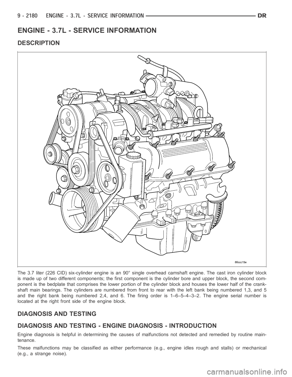
The 3.7 liter (226 CID) six-cylinder engine is an 90° single overhead camshaft engine. The cast iron cylinder block
is made up of two different components; the first component is the cylinderbore and upper block, the second com-
ponent is the bedplate that comprises the lower portion of the cylinder block and houses the lower half of the crank-
shaft main bearings. The cylinders are numbered from front to rear with theleft bank being numbered 1,3, and 5
and the right bank being numbered 2,4, and 6. The firing order is 1–6–5–4–3–2. The engine serial number is
located at the right front side of the engine block.
DIAGNOSIS AND TESTING
DIAGNOSIS AND TESTING - ENGINE DIAGNOSIS - INTRODUCTION
Engine diagnosis is helpful in determining the causes of malfunctions notdetected and remedied by routine main-
tenance.
These malfunctions may be classified as either performance (e.g., engineidles rough and stalls) or mechanical
(e.g., a strange noise).
Page 1490 of 5267
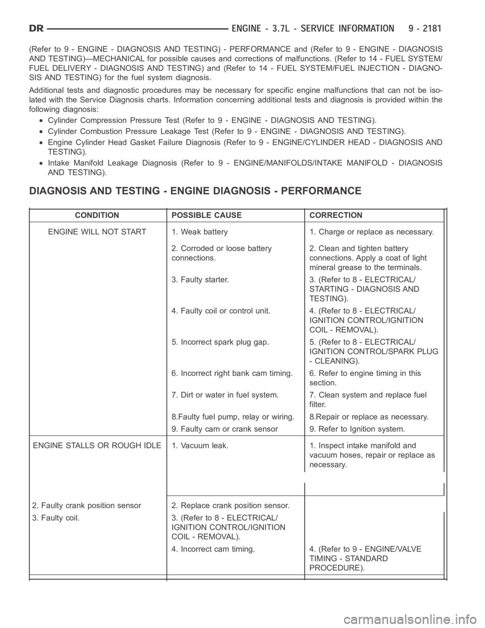
(Refer to 9 - ENGINE - DIAGNOSIS AND TESTING) - PERFORMANCE and (Refer to 9 - ENGINE - DIAGNOSIS
AND TESTING)—MECHANICAL for possible causes and corrections of malfunctions. (Refer to 14 - FUEL SYSTEM/
FUEL DELIVERY - DIAGNOSIS AND TESTING) and (Refer to 14 - FUEL SYSTEM/FUEL INJECTION - DIAGNO-
SIS AND TESTING) for the fuel system diagnosis.
Additional tests and diagnostic procedures may be necessary for specificengine malfunctions that can not be iso-
lated with the Service Diagnosis charts. Information concerning additional tests and diagnosis is provided within the
following diagnosis:
Cylinder Compression Pressure Test (Refer to 9 - ENGINE - DIAGNOSIS AND TESTING).
Cylinder Combustion Pressure LeakageTest (Refer to 9 - ENGINE - DIAGNOSISAND TESTING).
Engine Cylinder Head Gasket Failure Diagnosis (Refer to 9 - ENGINE/CYLINDER HEAD - DIAGNOSIS AND
TESTING).
Intake Manifold Leakage Diagnosis (Refer to 9 - ENGINE/MANIFOLDS/INTAKEMANIFOLD - DIAGNOSIS
AND TESTING).
DIAGNOSIS AND TESTING - ENGINE DIAGNOSIS - PERFORMANCE
CONDITION POSSIBLE CAUSE CORRECTION
ENGINE WILL NOT START 1. Weak battery 1. Charge or replace as necessary.
2. Corroded or loose battery
connections.2. Clean and tighten battery
connections. Apply a coat of light
mineral grease to the terminals.
3. Faulty starter. 3. (Refer to 8 - ELECTRICAL/
STARTING - DIAGNOSIS AND
TESTING).
4. Faulty coil or control unit. 4. (Refer to 8 - ELECTRICAL/
IGNITION CONTROL/IGNITION
COIL - REMOVAL).
5. Incorrect spark plug gap. 5. (Refer to 8 - ELECTRICAL/
IGNITION CONTROL/SPARK PLUG
- CLEANING).
6. Incorrect right bank cam timing. 6. Refer to engine timing in this
section.
7. Dirt or water in fuel system. 7. Clean system and replace fuel
filter.
8.Faulty fuel pump, relay or wiring. 8.Repair or replace as necessary.
9. Faulty cam or crank sensor 9. Refer to Ignition system.
ENGINE STALLS OR ROUGH IDLE 1. Vacuum leak. 1. Inspect intake manifold and
vacuum hoses, repair or replace as
necessary.
2. Faulty crank position sensor 2. Replace crank position sensor.
3. Faulty coil. 3. (Refer to 8 - ELECTRICAL/
IGNITION CONTROL/IGNITION
COIL - REMOVAL).
4. Incorrect cam timing. 4. (Refer to 9 - ENGINE/VALVE
TIMING - STANDARD
PROCEDURE).
Page 1491 of 5267
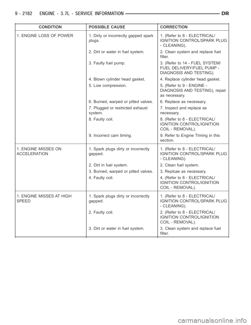
CONDITION POSSIBLE CAUSE CORRECTION
1. ENGINE LOSS OF POWER 1. Dirty or incorrectly gapped spark
plugs.1. (Refer to 8 - ELECTRICAL/
IGNITION CONTROL/SPARK PLUG
- CLEANING).
2. Dirt or water in fuel system. 2. Clean system and replace fuel
filter.
3. Faulty fuel pump. 3. (Refer to 14 - FUEL SYSTEM/
FUEL DELIVERY/FUEL PUMP -
DIAGNOSIS AND TESTING).
4. Blown cylinder head gasket. 4. Replace cylinder head gasket.
5. Low compression. 5. (Refer to 9 - ENGINE -
DIAGNOSIS AND TESTING), repair
as necessary.
6. Burned, warped or pitted valves. 6. Replace as necessary.
7. Plugged or restricted exhaust
system.7. Inspect and replace as
necessary.
8. Faulty coil. 8. (Refer to 8 - ELECTRICAL/
IGNITION CONTROL/IGNITION
COIL - REMOVAL).
9. Incorrect cam timing. 9. Refer to Engine TIming in this
section.
1. ENGINE MISSES ON
ACCELERATION1. Spark plugs dirty or incorrectly
gapped.1. (Refer to 8 - ELECTRICAL/
IGNITION CONTROL/SPARK PLUG
- CLEANING).
2. Dirt in fuel system. 2. Clean fuel system.
3. Burned, warped or pitted valves. 3. Replcae as necessary.
4. Faulty coil. 4. (Refer to 8 - ELECTRICAL/
IGNITION CONTROL/IGNITION
COIL - REMOVAL).
1. ENGINE MISSES AT HIGH
SPEED1. Spark plugs dirty or incorrectly
gapped.1. (Refer to 8 - ELECTRICAL/
IGNITION CONTROL/SPARK PLUG
- CLEANING).
2. Faulty coil. 2. (Refer to 8 - ELECTRICAL/
IGNITION CONTROL/IGNITION
COIL - REMOVAL).
3. Dirt or water in fuel system. 3. Clean system and replace fuel
filter.
Page 1492 of 5267
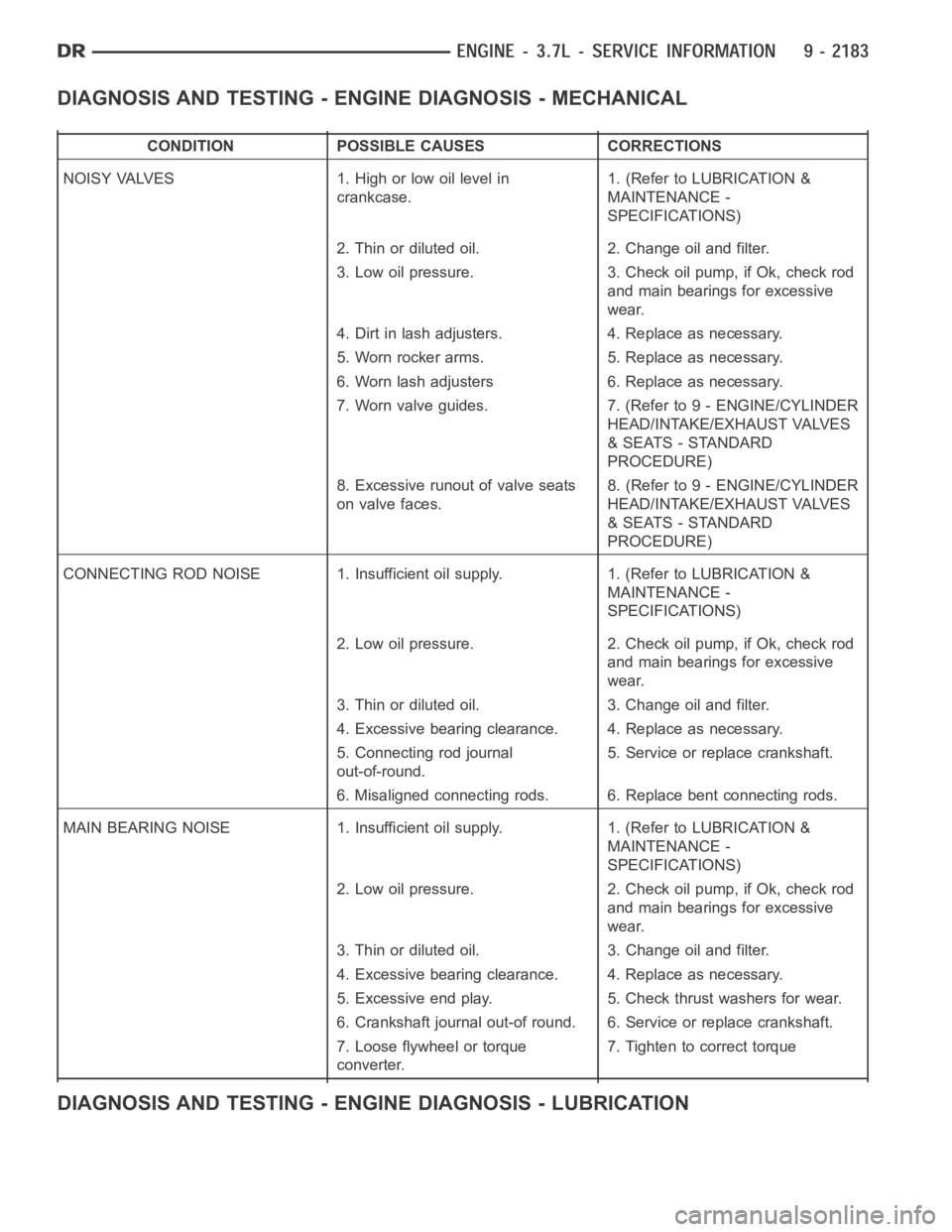
DIAGNOSIS AND TESTING - ENGINE DIAGNOSIS - MECHANICAL
CONDITION POSSIBLE CAUSES CORRECTIONS
NOISY VALVES 1. High or low oil level in
crankcase.1. (Refer to LUBRICATION &
MAINTENANCE -
SPECIFICATIONS)
2. Thin or diluted oil. 2. Change oil and filter.
3. Low oil pressure. 3. Check oil pump, if Ok, check rod
and main bearings for excessive
wear.
4. Dirt in lash adjusters. 4. Replace as necessary.
5. Worn rocker arms. 5. Replace as necessary.
6. Worn lash adjusters 6. Replace as necessary.
7. Worn valve guides. 7. (Refer to 9 - ENGINE/CYLINDER
HEAD/INTAKE/EXHAUST VALVES
& SEATS - STANDARD
PROCEDURE)
8. Excessive runout of valve seats
on valve faces.8. (Refer to 9 - ENGINE/CYLINDER
HEAD/INTAKE/EXHAUST VALVES
& SEATS - STANDARD
PROCEDURE)
CONNECTING ROD NOISE 1. Insufficient oil supply. 1. (Refer to LUBRICATION&
MAINTENANCE -
SPECIFICATIONS)
2. Low oil pressure. 2. Check oil pump, if Ok, check rod
and main bearings for excessive
wear.
3. Thin or diluted oil. 3. Change oil and filter.
4. Excessive bearing clearance. 4. Replace as necessary.
5. Connecting rod journal
out-of-round.5. Service or replace crankshaft.
6. Misaligned connecting rods. 6. Replace bent connecting rods.
MAIN BEARING NOISE 1. Insufficient oil supply. 1. (Refer to LUBRICATION &
MAINTENANCE -
SPECIFICATIONS)
2. Low oil pressure. 2. Check oil pump, if Ok, check rod
and main bearings for excessive
wear.
3. Thin or diluted oil. 3. Change oil and filter.
4. Excessive bearing clearance. 4. Replace as necessary.
5. Excessive end play. 5. Check thrust washers for wear.
6. Crankshaft journal out-of round. 6. Service or replace crankshaft.
7. Loose flywheel or torque
converter.7. Tighten to correct torque
DIAGNOSIS AND TESTING - ENGINE DIAGNOSIS - LUBRICATION
Page 1493 of 5267
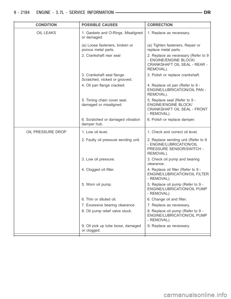
CONDITION POSSIBLE CAUSES CORRECTION
OIL LEAKS 1. Gaskets and O-Rings. Misaligned
or damaged.1. Replace as necessary.
(a) Loose fasteners, broken or
porous metal parts.(a) Tighten fasteners, Repair or
replace metal parts.
2. Crankshaft rear seal 2. Replace as necessary (Refer to 9
- ENGINE/ENGINE BLOCK/
CRANKSHAFT OIL SEAL - REAR -
REMOVAL).
3. Crankshaft seal flange.
Scratched, nicked or grooved.3. Polish or replace crankshaft.
4. Oil pan flange cracked. 4. Replace oil pan (Refer to 9 -
ENGINE/LUBRICATION/OIL PAN -
REMOVAL).
5. Timing chain cover seal,
damaged or misaligned.5. Replace seal (Refer to 9 -
ENGINE/ENGINE BLOCK/
CRANKSHAFT OIL SEAL - FRONT
- REMOVAL).
6. Scratched or damaged vibration
damper hub.6. Polish or replace damper.
OIL PRESSURE DROP 1. Low oil level. 1. Check and correct oil level.
2. Faulty oil pressure sending unit. 2. Replace sending unit (Refer to 9
- ENGINE/LUBRICATION/OIL
PRESSURE SENSOR/SWITCH -
REMOVAL).
3. Low oil pressure. 3. Check oil pump and bearing
clearance.
4. Clogged oil filter. 4. Replace oil filter (Refer to 9 -
ENGINE/LUBRICATION/OIL FILTER
- REMOVAL).
5. Worn oil pump. 5. Replace oil pump (Refer to 9 -
ENGINE/LUBRICATION/OIL PUMP
- REMOVAL).
6. Thin or diluted oil. 6. Change oil and filter.
7. Excessive bearing clearance. 7. Replace as necessary.
8. Oil pump relief valve stuck. 8. Replace oil pump (Refer to 9 -
ENGINE/LUBRICATION/OIL PUMP
- REMOVAL).
9. Oil pick up tube loose, damaged
or clogged.9. Replace as necessary.