2006 DODGE RAM SRT-10 oil
[x] Cancel search: oilPage 3974 of 5267
REGULATOR VALVE
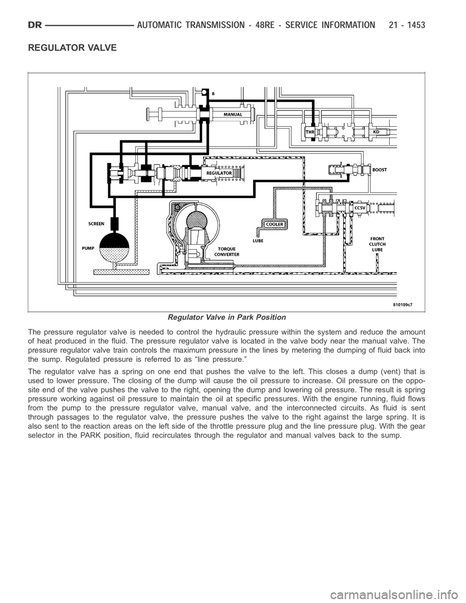
The pressure regulator valve is needed to control the hydraulic pressure within the system and reduce the amount
of heat produced in the fluid. The pressure regulator valve is located in the valve body near the manual valve. The
pressure regulator valve train controls the maximum pressure in the linesby metering the dumping of fluid back into
the sump. Regulated pressure is referred to as “line pressure.”
The regulator valve has a spring on one end that pushes the valve to the left.This closes a dump (vent) that is
used to lower pressure. The closing of the dump will cause the oil pressure to increase. Oil pressure on the oppo-
site end of the valve pushes the valve to the right, opening the dump and lowering oil pressure. The result is spring
pressure working against oil pressureto maintain the oil at specific pressures. With the engine running, fluid flows
from the pump to the pressure regulator valve, manual valve, and the interconnected circuits. As fluid is sent
through passages to the regulator valve, the pressure pushes the valve to the right against the large spring. It is
also sent to the reaction areas on the left side of the throttle pressure plug and the line pressure plug. With the gear
selector in the PARK position, fluid recirculates through the regulator and manual valves back to the sump.
Regulator Valve in Park Position
Page 3991 of 5267
Once the TCC control valve has moved to the right, line pressure is directedto the tip of the switch valve, forcing
the valve to the right. The switch valve now vents oil from the front of the piston in the torque converter, and sup-
plies line pressure to the (rear) apply side of the torque converter piston. This pressure differential causes the piston
to apply against the friction material, cutting off any further flow of line pressure oil. After the switch valve is shuttled
right allowing line pressure to engage the TCC, torque converter pressureis directed past the switch valve into the
transmission cooler and lubrication circuits.
CONVERTER CLUTCH LOCK-UP VALVE
The torque converter clutch (TCC) lock-up valve controls the back (ON) side of the torque converter clutch. When
the PCM energizes the TCC solenoid to engage the converter clutch piston, pressure is applied to the TCC lock-up
valve which moves to the right and applies pressure to the torque converterclutch.
CONVERTER CLUTCH LOCK-UP TIMING VALVE
The torque converter clutch (TCC) lock-up timing valve is there to block any 4-3 downshift until the TCC is com-
pletely unlocked and the clutch is disengaged.
SHUTTLE VALVE
The assembly is contained in a bore in the valve body above the shift valves.When the manual valve is positioned
in the Drive range, throttle pressure acts on the throttle plug of the shuttle valve to move it against a spring, increas-
ing the spring force on the shuttle valve. During a part or full throttle 1-2upshift, the throttle plug is bottomed by
throttle pressure, holding the shuttle valve to the right against governor pressure, and opening a by–pass circuit.
The shuttle valve controls the quality of the kickdown shift by restricting the rate of fluid discharge from the front
clutch and servo release circuits. During a 3-2 kickdown, fluid discharges through the shuttle by-pass circuit. When
the shuttle valve closes the by-pass circuit, fluid discharge is restricted and controlled for the application of the front
band. During a 2-3 “lift foot” upshift, the shuttle valve by-passes the restriction to allow full fluid flow through the
by-pass groove for a faster release of the band.
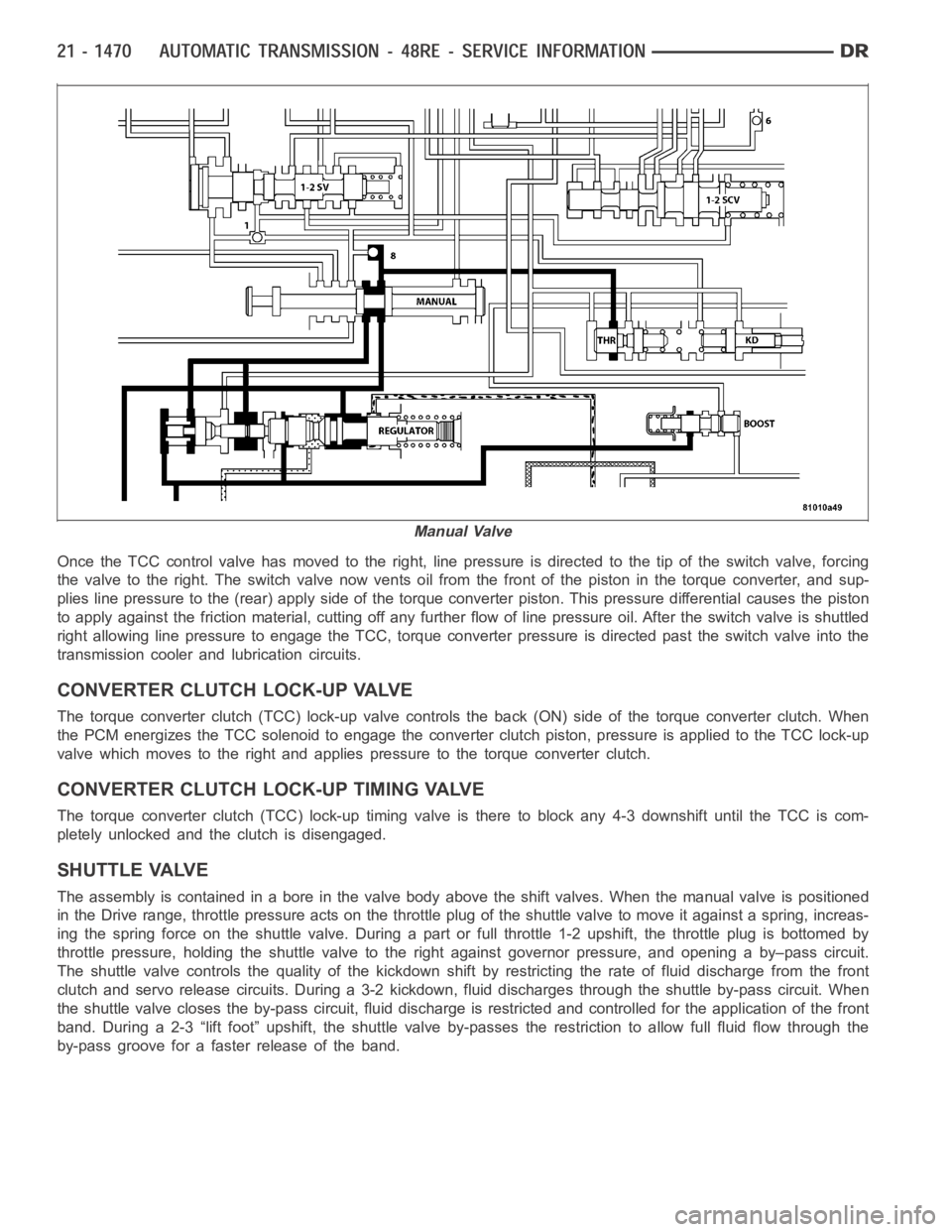
Manual Valve
Page 3993 of 5267
Manual lever detent ball.
Throttle lever.
Fluid filter.
Pressure adjusting screw bracket.
Governor pressure solenoid.
Governor pressure sensor (includes transmission temperature thermistor).
Converter clutch/overdrive solenoid assembly and harness.
Governor housing gasket.
Solenoid case connector O-rings.
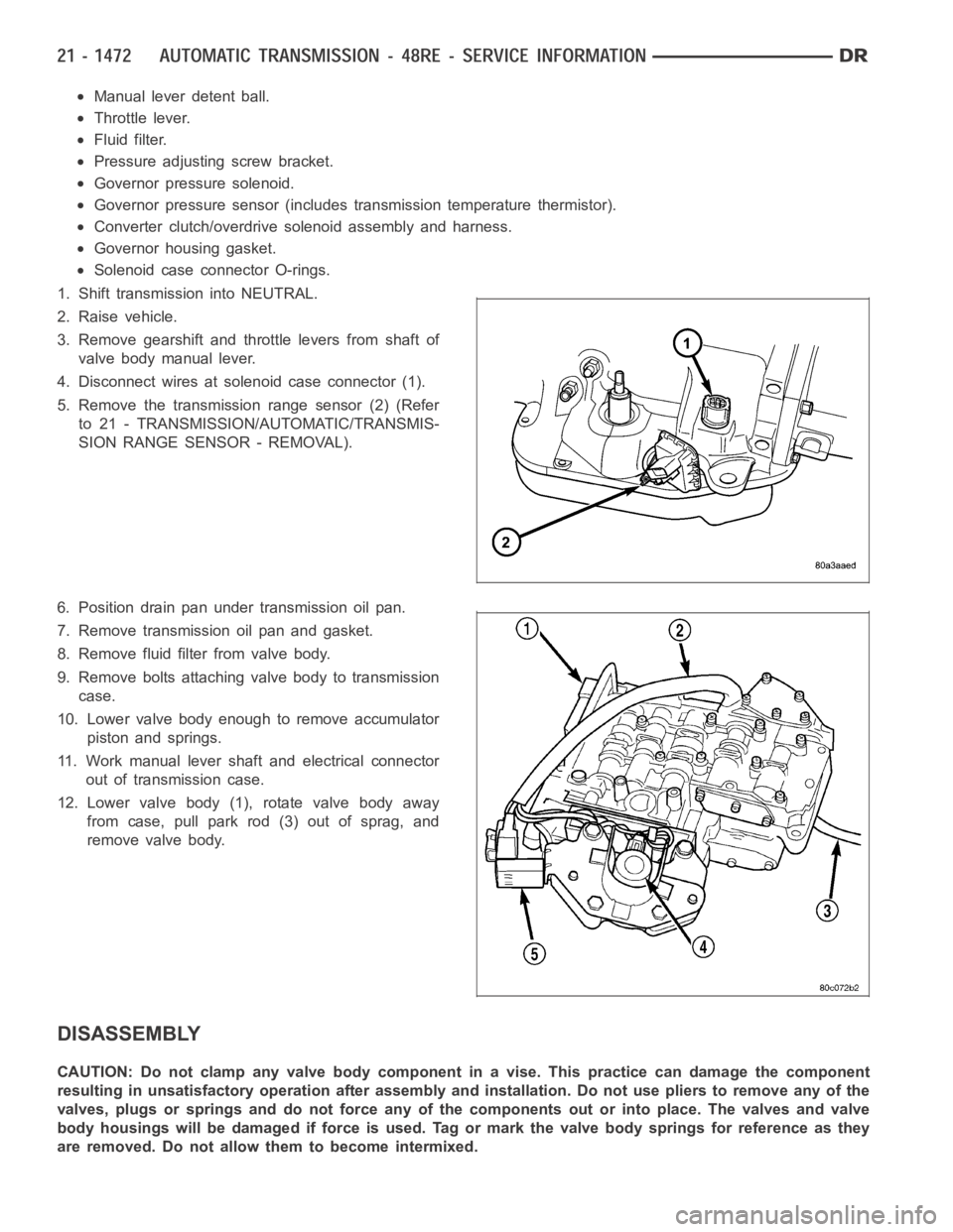
1. Shift transmission into NEUTRAL.
2. Raise vehicle.
3. Remove gearshift and throttle levers from shaft of
valve body manual lever.
4. Disconnect wires at solenoid case connector (1).
5. Remove the transmission range sensor (2) (Refer
to 21 - TRANSMISSION/AUTOMATIC/TRANSMIS-
SION RANGE SENSOR - REMOVAL).
6. Position drain pan under transmission oil pan.
7. Remove transmission oil pan and gasket.
8. Remove fluid filter from valve body.
9. Remove bolts attaching valve body to transmission
case.
10. Lower valve body enough to remove accumulator
piston and springs.
11. Work manual lever shaft and electrical connector
out of transmission case.
12. Lower valve body (1), rotate valve body away
from case, pull park rod (3) out of sprag, and
remove valve body.
DISASSEMBLY
CAUTION: Do not clamp any valve body component in a vise. This practice can damage the component
resulting in unsatisfactory operation after assembly and installation.Do not use pliers to remove any of the
valves, plugs or springs and do not force any of the components out or into place. The valves and valve
body housings will be damaged if force is used. Tag or mark the valve body springs for reference as they
are removed. Do not allow them to become intermixed.
Page 4007 of 5267
sharpness of these edges is vitally important. The edges prevent foreign matter from lodging between the valves
and plugs and the bore.
Inspect all the valve and plug bores in the valve body. Use a penlight to viewthe bore interiors. Replace the valve
body if any bores are distorted or scored. Inspect all of the valve body springs. The springs must be free of dis-
tortion, warpage or broken coils.
Check the two separator plates for distortion or damage of any kind. Inspect the upper housing, lower housing, 3-4
accumulator housing, and transfer plate carefully. Be sure all fluid passages are clean and clear. Check condition of
the upper housing and transfer plate check balls as well. The check balls and ball seats must not be worn or dam-
aged.
Trial fit each valve and plug in its bore to check freedom of operation. Whenclean and dry, the valves and plugs
shoulddropfreelyintothebores.
Valve body bores do not change dimensionally with use. If the valve body functioned correctly when new, it will
continue to operate properly after cleaning and inspection. It should notbe necessary to replace a valve body
assembly unless it is damaged in handling.
The only serviceable valve body components are listed below. The remaining valve body components are serviced
only as part of a complete valve body assembly. Serviceable parts are:
dual solenoid and harness assembly
solenoid gasket
solenoid case connector O-rings and shoulder bolt
switch valve and spring
pressure adjusting screw and bracket assembly
throttle lever
manual lever and shaft seal
throttle lever shaft seal, washer, and E-clip
fluid filter and screws
detent ball and spring
valve body screws
governor pressure solenoid
governor pressure sensor and retaining clip
park lock rod and E-clip
ASSEMBLY
CAUTION: Do not force valves or plugs into place during reassembly. If the valve body bores, valves and
plugs are free of distortion or burrs, the valve body components should allslide into place easily. In addi-
tion, do not overtighten the transfer plate and valve body screws during reassembly. Overtightening can
distort the housings resulting in valve sticking, cross leakage and unsatisfactory operation. Tighten valve
body screws to recommended torque only.
Page 4018 of 5267
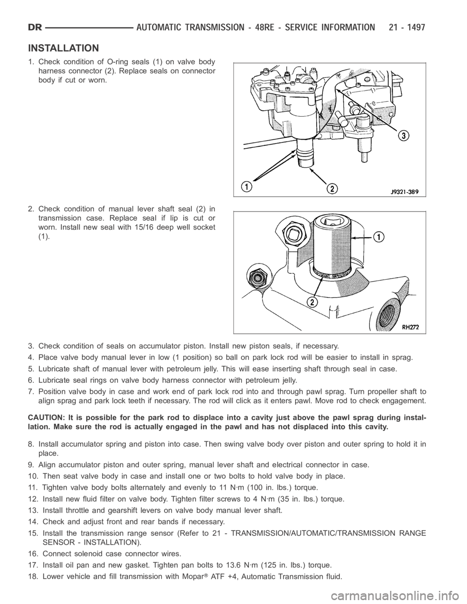
INSTALLATION
1. Check condition of O-ring seals (1) on valve body
harness connector (2). Replace seals on connector
body if cut or worn.
2. Check condition of manual lever shaft seal (2) in
transmission case. Replace seal if lip is cut or
worn. Install new seal with 15/16 deep well socket
(1).
3. Check condition of seals on accumulator piston. Install new piston seals, if necessary.
4. Place valve body manual lever in low (1 position) so ball on park lock rod will be easier to install in sprag.
5. Lubricate shaft of manual lever with petroleum jelly. This will ease inserting shaft through seal in case.
6. Lubricate seal rings on valve body harness connector with petroleum jelly.
7. Position valve body in case and work end of park lock rod into and through pawl sprag. Turn propeller shaft to
align sprag and park lock teeth if necessary. The rod will click as it enterspawl. Move rod to check engagement.
CAUTION: It is possible for the park rod to displace into a cavity just abovethe pawl sprag during instal-
lation. Make sure the rod is actually engaged in the pawl and has not displaced into this cavity.
8. Install accumulator spring and piston into case. Then swing valve body overpistonandouterspringtoholditin
place.
9. Align accumulator piston and outer spring, manual lever shaft and electrical connector in case.
10. Then seat valve body in case and install one or two bolts to hold valve bodyinplace.
11. Tighten valve body bolts alternately and evenly to 11 Nꞏm (100 in. lbs.)torque.
12. Install new fluid filter on valve body. Tighten filter screws to 4 Nꞏm (35 in. lbs.) torque.
13. Install throttle and gearshift levers on valve body manual lever shaft.
14. Check and adjust front and rear bands if necessary.
15. Install the transmission range sensor (Refer to 21 - TRANSMISSION/AUTOMATIC/TRANSMISSION RANGE
SENSOR - INSTALLATION).
16. Connect solenoid case connector wires.
17. Install oil pan and new gasket. Tighten pan bolts to 13.6 Nꞏm (125 in. lbs.) torque.
18. Lower vehicle and fill transmission with Mopar
ATF +4, Automatic Transmission fluid.
Page 4087 of 5267
Condition Possible Cause Correction
Lubricant leaking from output shaft
seal or vent.1) Transfer case overfilled. 1) Drain lubricant to the correct
level.
2) Vent closed or restricted. 2) Clear or replace vent as
necessary.
3) Output shaft seals damaged or
installed incorrectly.3) Replace seal as necessary.
Check to ensure that another
component, the propeller shaft slip
yoke for example, is not causing
damage to seal.
Abnormal tire wear. 1) Extended operation on hard, dry
surfaces in the 4H position.1) Operate vehicle in the 2H
position on hard, dry surfaces.
REMOVAL
1. Raise and support vehicle.
2. Remove skid plate, if equipped. (Refer to 13 - FRAMES & BUMPERS/FRAME/TRANSFER CASE SKID PLATE
- REMOVAL)
3. Position drain oil container under transfer case.
4. Remove transfer case drain plug and drain lubricant into container.
5. Disconnect vent hose and transfer case position sensor connector.
6. Disconnect shift rod from grommet in transfer case shift lever, or from floor shift arm whichever provides easy
access. Use channel lock style pliers to press rod out of lever grommet.
7. Support transmission with jack stand.
8. Mark front and rear propeller shafts for assembly reference.
9. Remove front and rear propeller shafts. (Refer to 3 - DIFFERENTIAL & DRIVELINE/PROPELLER SHAFT/PRO-
PELLER SHAFT - REMOVAL)
10. Support transfer case with suitable jack. Secure transfer case to jackwith safety chains.
11. Remove nuts attaching transfer case to transmission.
12. Move transfer case assembly rearward until free of transmission outputshaft.
13. Lower jack and move transfer case from under vehicle.
DISASSEMBLY
Position transfer case in a shallow drain pan. Remove drain plug and drain any remaining lubricant remaining in
case.
SHIFT LEVER AND FRONT OUTPUT SHAFT SEAL
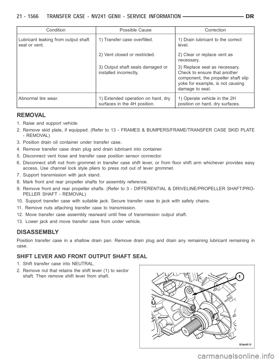
1. Shift transfer case into NEUTRAL.
2. Remove nut that retains the shift lever (1) to sector
shaft. Then remove shift lever from shaft.
Page 4090 of 5267
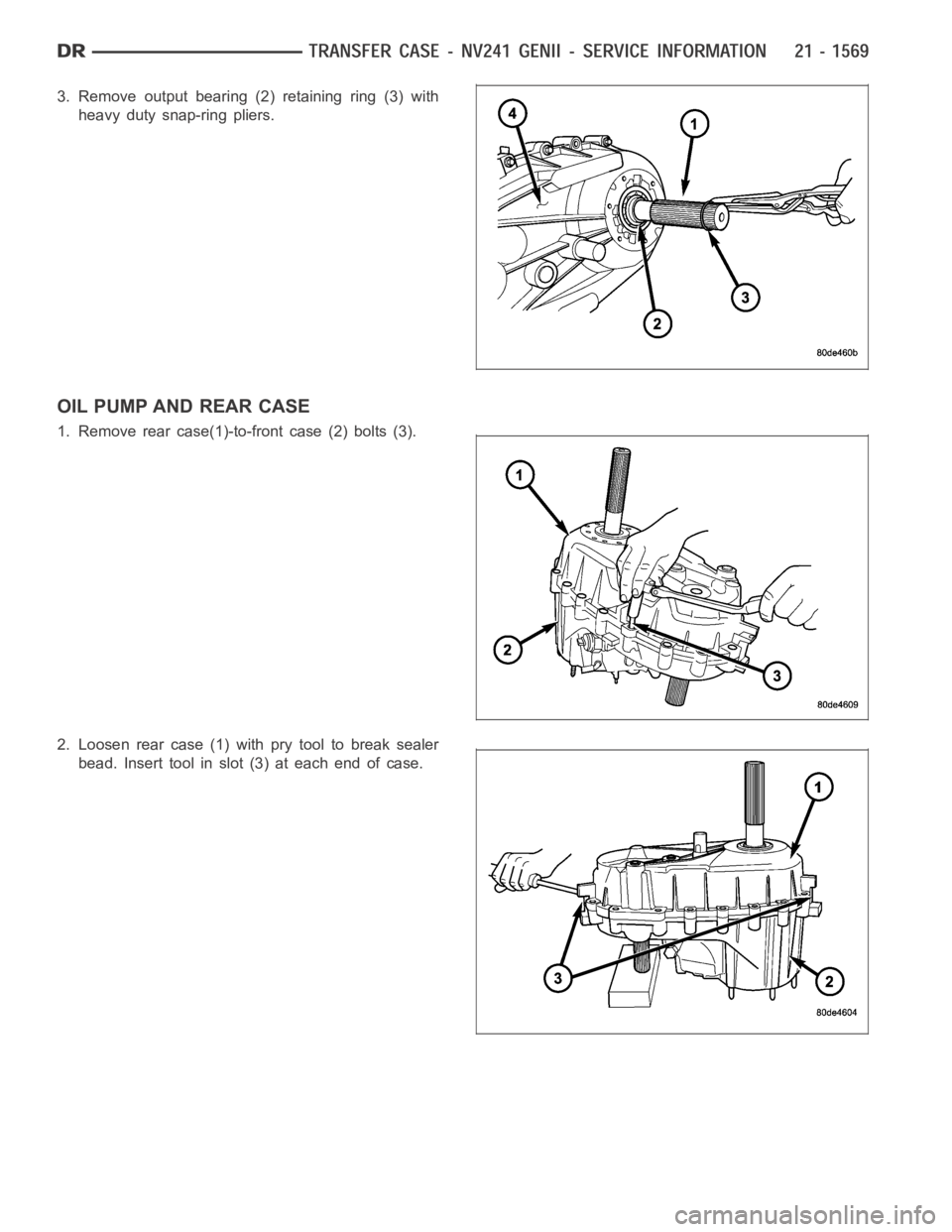
3. Remove output bearing (2) retaining ring (3) with
heavy duty snap-ring pliers.
OIL PUMP AND REAR CASE
1. Remove rear case(1)-to-front case (2) bolts (3).
2. Loosen rear case (1) with pry tool to break sealer
bead. Insert tool in slot (3) at each end of case.
Page 4091 of 5267
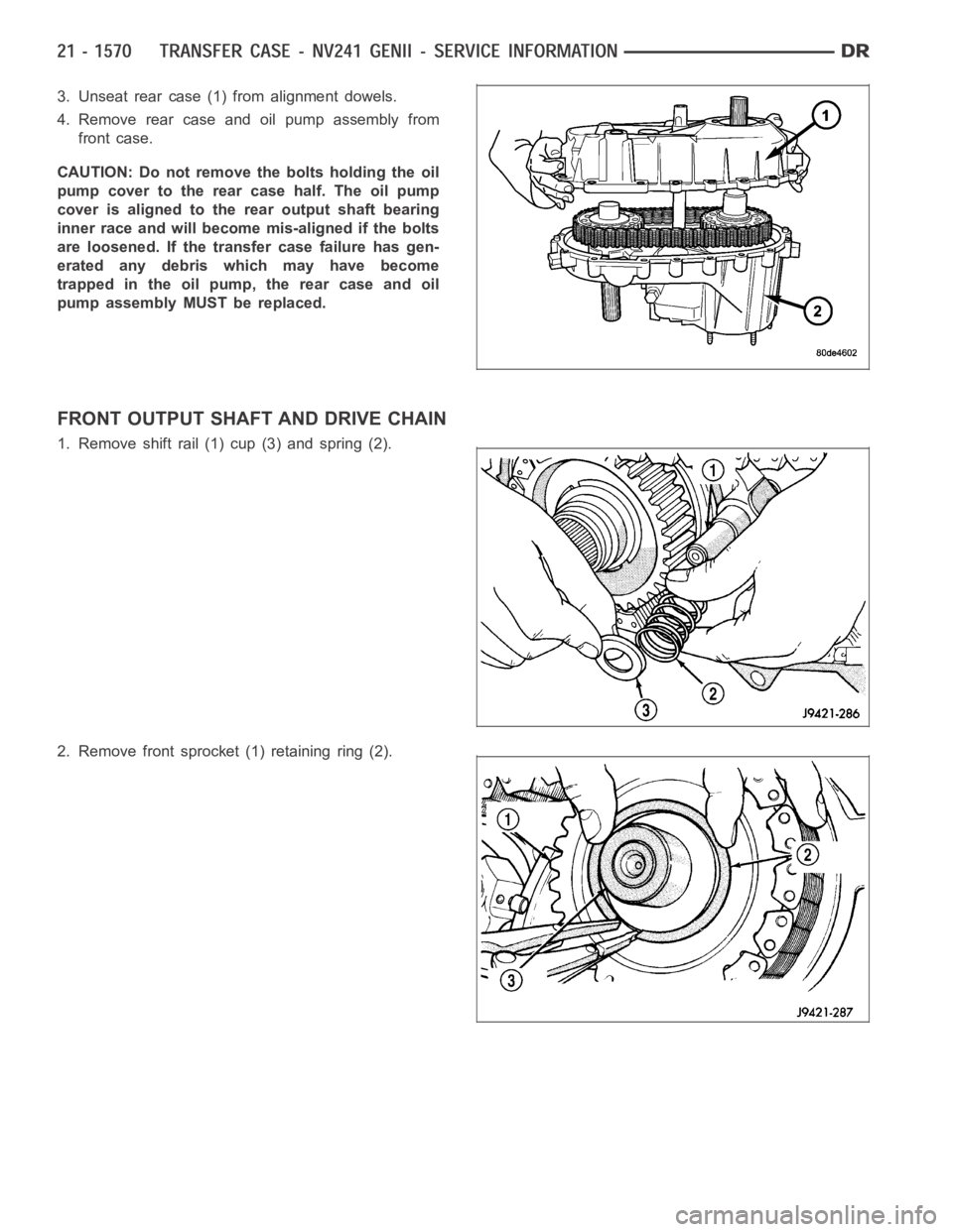
3. Unseat rear case (1) from alignment dowels.
4. Remove rear case and oil pump assembly from
front case.
CAUTION: Do not remove the bolts holding the oil
pump cover to the rear case half. The oil pump
cover is aligned to the rear output shaft bearing
inner race and will becomemis-aligned if the bolts
are loosened. If the transfer case failure has gen-
erated any debris which may have become
trapped in the oil pump, the rear case and oil
pump assembly MUST be replaced.
FRONT OUTPUT SHAFT AND DRIVE CHAIN
1. Remove shift rail (1) cup (3) and spring (2).
2. Remove front sprocket (1) retaining ring (2).