Page 4099 of 5267
3. Remove front tabbed thrust washer (1).
4. Remove input gear (1).
5. Remove rear tabbed thrust washer (2) from low
range gear (1).
CLEANING
Clean the transfer case parts with a standard parts cleaning solvent. Remove all traces of sealer from the cases
and retainers with a scraper and 3M™ all purpose cleaner. Use compressed air to remove solvent residue from oil
feed passages in the case halves, retainers, gears, and shafts.
Page 4100 of 5267
INSPECTION
MAINSHAFT/SPROCKET/HUB
Inspect the splines on the hub and shaft and the teeth on the sprocket. Minornicks and scratches can be smoothed
with an oilstone, however, replace any part that is damaged.
Check the contact surfaces in the sprocket bore and on the mainshaft. Minornicks and scratches can be smoothed
with 320-400 grit emery cloth but do not try to salvage the shaft if nicks or wear is severe.
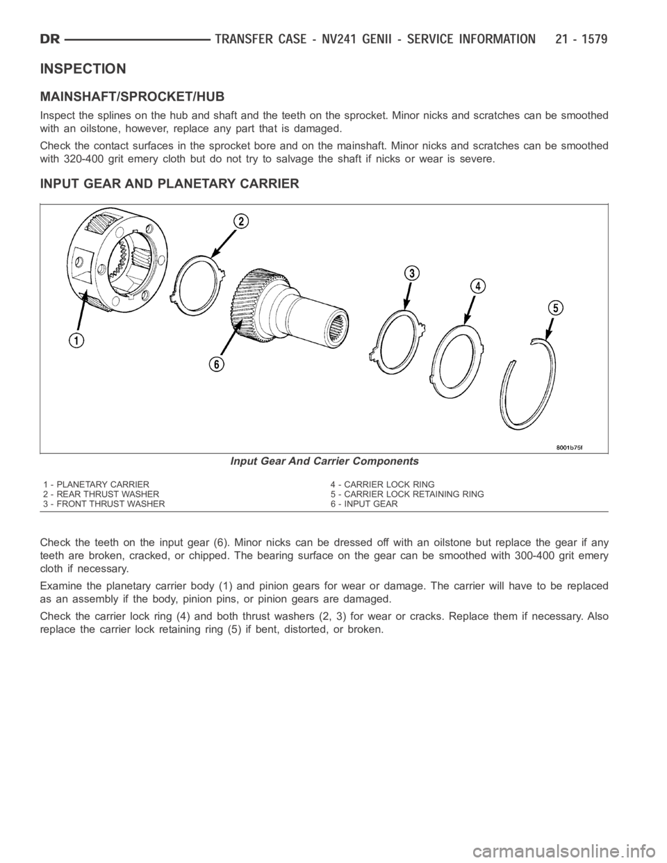
INPUT GEAR AND PLANETARY CARRIER
Check the teeth on the input gear (6). Minor nicks can be dressed off with an oilstone but replace the gear if any
teeth are broken, cracked, or chipped. The bearing surface on the gear can besmoothedwith300-400gritemery
cloth if necessary.
Examine the planetary carrier body (1) and pinion gears for wear or damage.The carrier will have to be replaced
as an assembly if the body, pinion pins, or pinion gears are damaged.
Check the carrier lock ring (4) and both thrust washers (2, 3) for wear or cracks. Replace them if necessary. Also
replace the carrier lock retaining ring (5) if bent, distorted, or broken.
Input Gear And Carrier Components
1 - PLANETARY CARRIER 4 - CARRIER LOCK RING
2 - REAR THRUST WASHER 5 - CARRIER LOCK RETAINING RING
3 - FRONT THRUST WASHER 6 - INPUT GEAR
Page 4102 of 5267
LOW RANGE ANNULUS GEAR
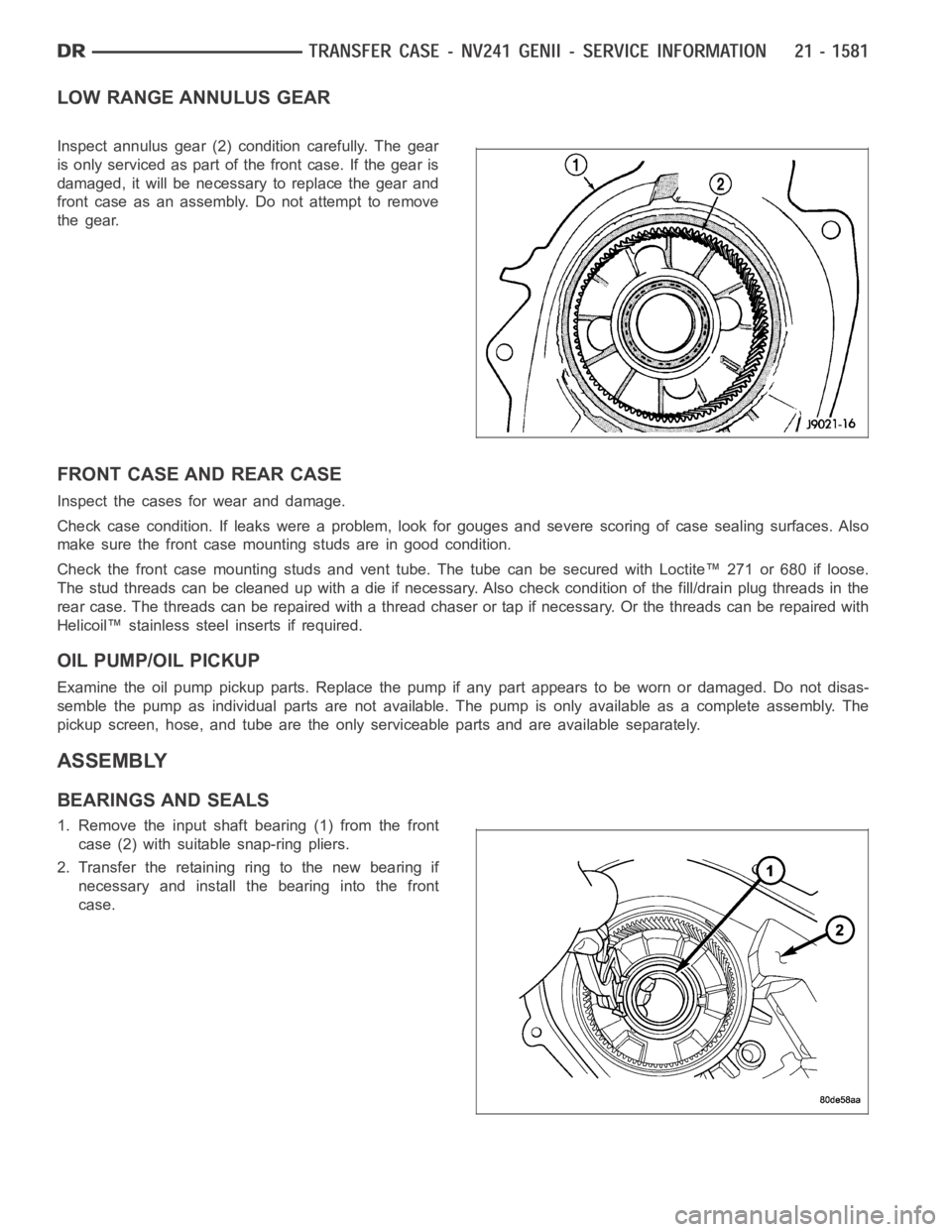
Inspect annulus gear (2) condition carefully. The gear
is only serviced as part of the front case. If the gear is
damaged, it will be necessary to replace the gear and
front case as an assembly. Do not attempt to remove
the gear.
FRONT CASE AND REAR CASE
Inspect the cases for wear and damage.
Check case condition. If leaks were a problem, look for gouges and severe scoring of case sealing surfaces. Also
make sure the front case mounting studs are in good condition.
Check the front case mounting studs and vent tube. The tube can be secured with Loctite™ 271 or 680 if loose.
Thestudthreadscanbecleanedupwithadieifnecessary.Alsocheckcondition of the fill/drain plug threads in the
rear case. The threads can be repaired with a thread chaser or tap if necessary. Or the threads can be repaired with
Helicoil™ stainless steel inserts if required.
OIL PUMP/OIL PICKUP
Examine the oil pump pickup parts. Replace the pump if any part appears to beworn or damaged. Do not disas-
semble the pump as individual parts are not available. The pump is only available as a complete assembly. The
pickup screen, hose, and tube are the only serviceable parts and are available separately.
ASSEMBLY
BEARINGS AND SEALS
1. Remove the input shaft bearing (1) from the front
case (2) with suitable snap-ring pliers.
2. Transfer the retaining ring to the new bearing if
necessary and install the bearing into the front
case.
Page 4114 of 5267
OIL PUMP AND REAR CASE
CAUTION: Do not remove the bolts holding the oil
pump cover to the rear case half. The oil pump
cover is aligned to the rear output shaft inner
bearing race and will become mis-aligned if the
bolts are loosened. If the transfer case failure has
generated any debris which may have become
trapped in the oil pump. the rear case and oil
pump assembly MUST be replaced.
1. Apply bead of Mopar
Gasket Maker, or equivalent,
to mating surface of front case. Keep sealer bead
width to maximum of 3/16 inch. Do not use exces-
sive amount of sealer as excess will be displaced
into case interior.
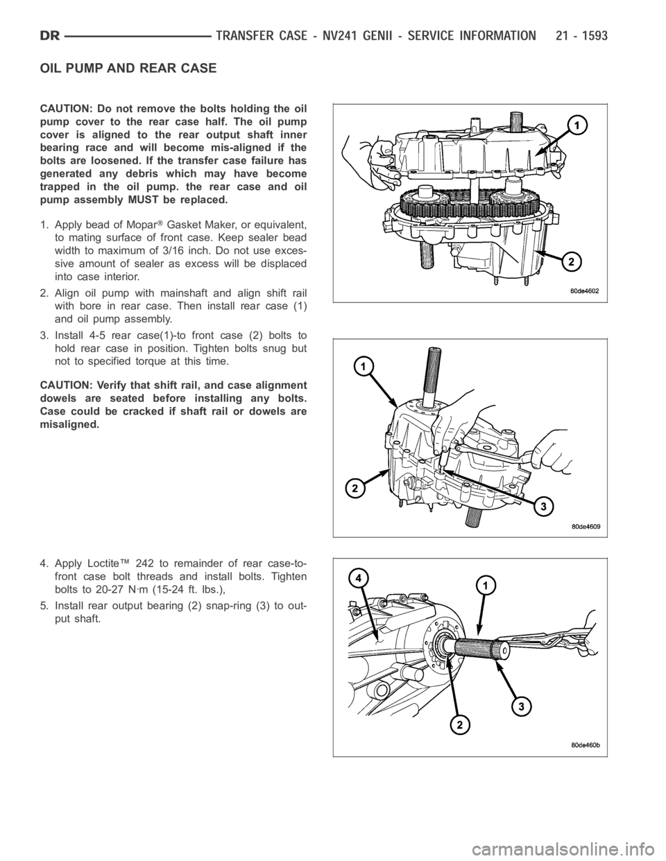
2. Align oil pump with mainshaft and align shift rail
with bore in rear case. Then install rear case (1)
and oil pump assembly.
3. Install 4-5 rear case(1)-to front case (2) bolts to
hold rear case in position. Tighten bolts snug but
not to specified torque at this time.
CAUTION: Verify that shift rail, and case alignment
dowels are seated before installing any bolts.
Case could be cracked if shaft rail or dowels are
misaligned.
4. Apply Loctite™ 242 to remainder of rear case-to-
front case bolt threads and install bolts. Tighten
bolts to 20-27 Nꞏm (15-24 ft. lbs.),
5. Install rear output bearing (2) snap-ring (3) to out-
put shaft.
Page 4115 of 5267
SEAL BOOT
1. Install the front output shaft seal slinger with Oil Slinger Installer 8840. Install the slinger onto the shaft until the
tool contacts the rear of the output shaft.
2. Install a new seal boot clamp onto the seal boot.
3. Install the seal boot and clamp onto the slinger hub and tighten the clampwith Crimp Tool C-4975-A.
REAR EXTENSION
1. Install new seal in rear extension housing seal with
Seal Installer D-163 and universal Handle C-4171..
2. Apply bead of Mopar
Gasket Maker, or equivalent,
to mating surface of rear extension housing. Keep
sealer bead width to maximum of 3/16 inch. Do not
use excessive amount of sealer as excess could
be displaced into output bearing.
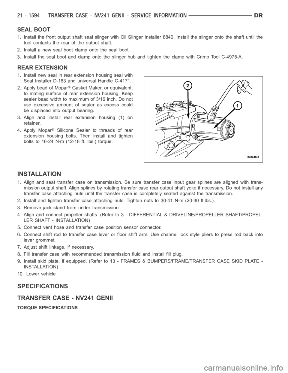
3. Align and install rear extension housing (1) on
retainer.
4. Apply Mopar
Silicone Sealer to threads of rear
extension housing bolts. Then install and tighten
bolts to 16-24 Nꞏm (12-18 ft. lbs.) torque.
INSTALLATION
1. Align and seat transfer case on transmission. Be sure transfer case input gear splines are aligned with trans-
mission output shaft. Align splines by rotating transfer case rear outputshaft yoke if necessary. Do not install any
transfer case attaching nuts until the transfer case is completely seatedagainst the transmission.
2. Install and tighten transfer case attaching nuts. Tighten nuts to 30-41Nꞏm (20-30 ft.lbs.).
3. Remove jack stand from under transmission.
4. Align and connect propeller shafts. (Refer to 3 - DIFFERENTIAL & DRIVELINE/PROPELLER SHAFT/PROPEL-
LER SHAFT - INSTALLATION)
5. Connect vent hose and transfer case position sensor connector.
6. Connect shift rod to transfer case lever or floor shift arm. Use channel lock style pliers to press rod back into
lever grommet.
7. Adjust shift linkage, if necessary.
8. Fill transfer case with recommended transmission fluid and install fillplug.
9. Install skid plate, if equipped. (Refer to 13 - FRAMES & BUMPERS/FRAME/TRANSFER CASE SKID PLATE -
INSTALLATION)
10. Lower vehicle
SPECIFICATIONS
TRANSFER CASE - NV241 GENII
TORQUE SPECIFICATIONS
Page 4116 of 5267
DESCRIPTION N-m Ft. Lbs. In. Lbs.
Plug, Detent 16-24 12-18 -
Plug, Drain/Fill 20-34 15-25 -
Bolt, Extension Housing 16-24 12-18 -
Bolt, Case Half 20-27 15-24 -
Screw, Oil Pump 12-16 8-12 -
Nut, Range Lever 27-34 20-25 -
Sector Support 27-42 20-30 -
Nuts, Mounting 30-41 20-30 -
Position Sensor 20-34 16-25 -
Page 4122 of 5267
5. Using a suitable pry tool (2), remove the slinger (1)
from the output shaft using care not to damage the
shaft.
6. Using a screw and a slide hammer, remove the
front output shaft seal.
INSTALLATION
1. Install the new front output shaft seal with Seal Installer MB991168A.
2. Install the front output shaft seal slinger with Oil Slinger Installer 8840. Install the slinger onto the shaft until the
tool contacts the rear of the output shaft.
3. Install a new seal boot clamp onto the seal boot.
4. Install the seal boot and clamp onto the slinger hub and tighten the clampwith Crimp Tool C-4975-A.
5. Install front propeller shaft (Refer to 3 - DIFFERENTIAL & DRIVELINE/PROPELLER SHAFT/PROPELLER
SHAFT - INSTALLATION).
Page 4129 of 5267
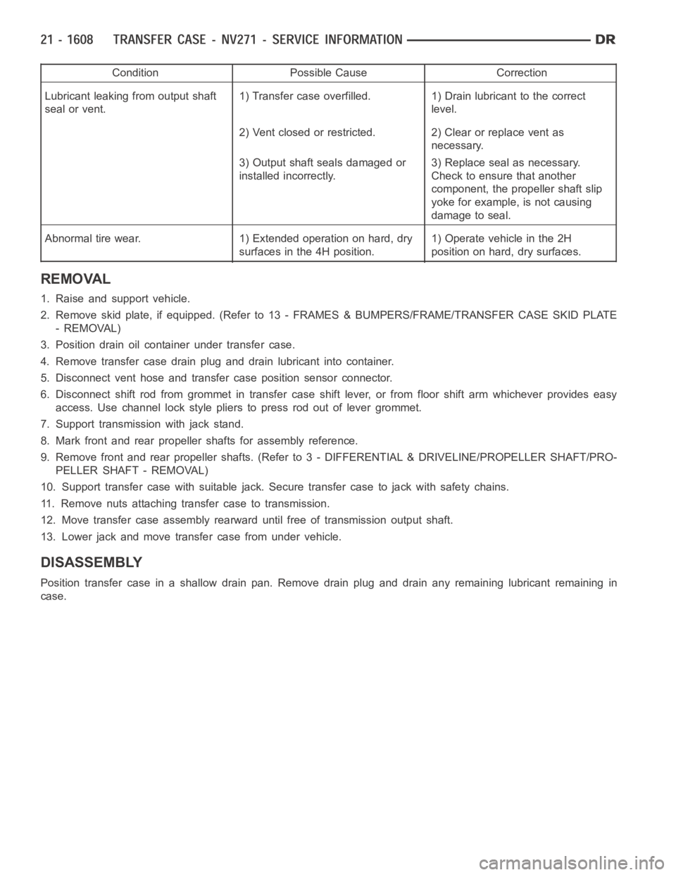
Condition Possible Cause Correction
Lubricant leaking from output shaft
seal or vent.1) Transfer case overfilled. 1) Drain lubricant to the correct
level.
2) Vent closed or restricted. 2) Clear or replace vent as
necessary.
3) Output shaft seals damaged or
installed incorrectly.3) Replace seal as necessary.
Check to ensure that another
component, the propeller shaft slip
yoke for example, is not causing
damage to seal.
Abnormal tire wear. 1) Extended operation on hard, dry
surfaces in the 4H position.1) Operate vehicle in the 2H
position on hard, dry surfaces.
REMOVAL
1. Raise and support vehicle.
2. Remove skid plate, if equipped. (Refer to 13 - FRAMES & BUMPERS/FRAME/TRANSFER CASE SKID PLATE
- REMOVAL)
3. Position drain oil container under transfer case.
4. Remove transfer case drain plug and drain lubricant into container.
5. Disconnect vent hose and transfer case position sensor connector.
6. Disconnect shift rod from grommet in transfer case shift lever, or from floor shift arm whichever provides easy
access. Use channel lock style pliers to press rod out of lever grommet.
7. Support transmission with jack stand.
8. Mark front and rear propeller shafts for assembly reference.
9. Remove front and rear propeller shafts. (Refer to 3 - DIFFERENTIAL & DRIVELINE/PROPELLER SHAFT/PRO-
PELLER SHAFT - REMOVAL)
10. Support transfer case with suitable jack. Secure transfer case to jackwith safety chains.
11. Remove nuts attaching transfer case to transmission.
12. Move transfer case assembly rearward until free of transmission outputshaft.
13. Lower jack and move transfer case from under vehicle.
DISASSEMBLY
Position transfer case in a shallow drain pan. Remove drain plug and drain any remaining lubricant remaining in
case.