2006 DODGE RAM SRT-10 ignition
[x] Cancel search: ignitionPage 1460 of 5267
P1696-PCM FAILURE EEPROM WRITE DENIED
For a complete wiring diagramRefer to Section 8W.
When Monitored:
Ignition on and battery voltage greater than 10 volts.
Set Condition:
An attempt to program/write to the internal EEPROM failed, also checks at powerdown.
Possible Causes
SRI MILEAGE INVALID
PCM
Always perform the Pre-Diagnostic Troubleshooting procedure before proceeding. (Refer to 9 - ENGINE -
DIAGNOSIS AND TESTING)
Diagnostic Test
1.SCAN TOOL DISPLAYS WRITE FAILURE
Ignition on, engine not running.
With the scan tool, perform the SRI Memory Test.
Does the scan tool display Write Failure?
Ye s>>
Replace and program the Powertrain Control Module per Service Information.
Perform the POWERTRAIN VERIFICATION TEST. (Refer to 9 - ENGINE - STANDARD PROCEDURE)
No>>
Go To 2
2.SCAN TOOL DISPLAYS WRITE REFUSED
With the scan tool, perform the SRI Memory Test.
Does the scan tool display Write Refused?
Ye s>>
Go To 3
No>>
Go To 4
3.PCM REFUSED 2ND TEST
With the scan tool, perform the SRI Memory Test a second time.
NOTE: Retest the SRI Memory two more times.
Does the scan tool display Write Refused again?
Ye s>>
Replace and program the Powertrain Control Module per Service Information.
Perform the POWERTRAIN VERIFICATION TEST. (Refer to 9 - ENGINE - STANDARD PROCEDURE)
No>>
Te s t C o m p l e t e .
4.SCAN TOOL DISPLAYS SRI MILEAGE INVALID
With the scan tool, perform the SRI Memory Test.
Does the scan tool display SRI Mileage Invalid?
Ye s>>
Update the mileage and retest the SRI Memory.
Perform the POWERTRAIN VERIFICATION TEST. (Refer to 9 - ENGINE - STANDARD PROCEDURE)
No>>
Go To 5
Page 1463 of 5267
Possible Causes
(A103) FUSED B+ CIRCUIT
(Z429) BRAKE LAMP SWITCH GROUND CIRCUIT OPEN
BRAKE LAMP SWITCH
(B29) BRAKE SWITCH NO.1 SIGNAL CIRCUIT OPEN
(B29) BRAKE SWITCH NO.1 SIGNAL CIRCUIT SHORT TO GROUND
PCM
Always perform the Pre-Diagnostic Troubleshooting procedure before proceeding. (Refer to 9 - ENGINE -
DIAGNOSIS AND TESTING)
Diagnostic Test
1.SCAN TOOL DOES NOT SHOW BRAKE SW PRESSED OR RELEASED
Ignition on, engine not running.
With the scan tool in Inputs/Outputs, read the Brake Switch state.
While observing the scan tool display, press and release the brake pedal several times.
Does the scan tool display Brake Switch PRESSED and RELEASED?
Ye s>>
The Brake Lamp Switch is operating properly at this time.
Perform the POWERTRAIN VERIFICATION TEST. (Refer to 9 - ENGINE - STANDARD PROCEDURE)
No>>
Go To 2
2.(A103) FUSED B+ CIRCUIT OPEN
Turn the ignition off.
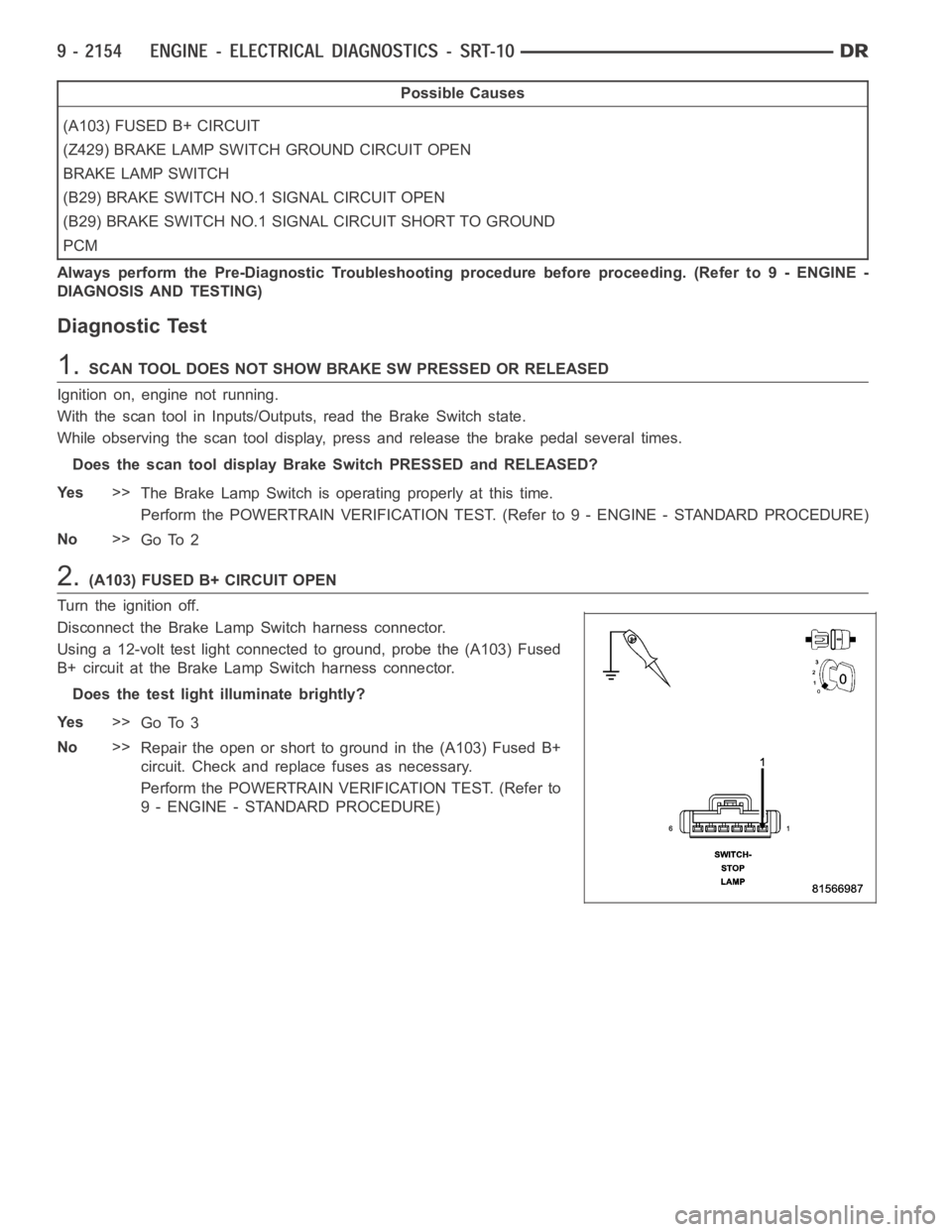
Disconnect the Brake Lamp Switch harness connector.
Using a 12-volt test light connected to ground, probe the (A103) Fused
B+ circuit at the Brake Lamp Switch harness connector.
Does the test light illuminate brightly?
Ye s>>
Go To 3
No>>
Repair the open or short to ground in the (A103) Fused B+
circuit. Check and replace fuses as necessary.
Perform the POWERTRAIN VERIFICATION TEST. (Refer to
9 - ENGINE - STANDARD PROCEDURE)
Page 1465 of 5267
6.(B29) BRAKE LAMP SWITCH SIGNAL CIRCUIT SHORTED TO GROUND
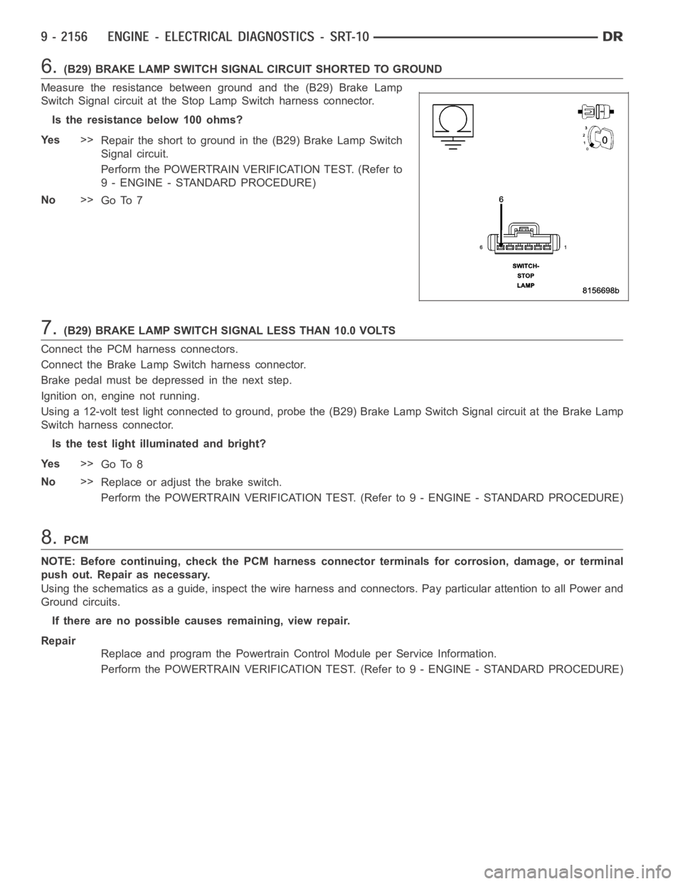
Measure the resistance between ground and the (B29) Brake Lamp
Switch Signal circuit at the Stop Lamp Switch harness connector.
Istheresistancebelow100ohms?
Ye s>>
Repair the short to ground in the (B29) Brake Lamp Switch
Signal circuit.
Perform the POWERTRAIN VERIFICATION TEST. (Refer to
9 - ENGINE - STANDARD PROCEDURE)
No>>
Go To 7
7.(B29) BRAKE LAMP SWITCH SIGNAL LESS THAN 10.0 VOLTS
Connect the PCM harness connectors.
Connect the Brake Lamp Switch harness connector.
Brake pedal must be depressed in the next step.
Ignition on, engine not running.
Using a 12-volt test light connected to ground, probe the (B29) Brake Lamp Switch Signal circuit at the Brake Lamp
Switch harness connector.
Is the test light illuminated and bright?
Ye s>>
Go To 8
No>>
Replace or adjust the brake switch.
Perform the POWERTRAIN VERIFICATION TEST. (Refer to 9 - ENGINE - STANDARD PROCEDURE)
8.PCM
NOTE: Before continuing, check the PCM harness connector terminals for corrosion, damage, or terminal
push out. Repair as necessary.
Using the schematics as a guide, inspect the wire harness and connectors. Pay particular attention to all Power and
Ground circuits.
If there are no possible causes remaining, view repair.
Repair
Replace and program the Powertrain Control Module per Service Information.
Perform the POWERTRAIN VERIFICATION TEST. (Refer to 9 - ENGINE - STANDARD PROCEDURE)
Page 1469 of 5267
Possible Causes
A/C SELECT CIRCUIT OPEN
A/C SELECT IN HVAC
PCM
A/C REQUEST CIRCUIT OPEN
REFRIGERATION SYSTEM NOT PROPERLY CHARGED
HIGH PRESS CUT-OFF SWITCH
LOW PRESSURE SWITCH
A/CCLUTCHCOIL
A/C COMPRESSOR CLUTCH GROUND CIRCUIT OPEN
(C3) A/C CLUTCH RELAY OUTPUT CIRCUIT OPEN
FUSED B+ CIRCUIT OPEN
A/CCLUTCHRELAY
Always perform the Pre-Diagnostic Troubleshooting procedure before proceeding. (Refer to 9 - ENGINE -
DIAGNOSIS AND TESTING)
Diagnostic Test
1.DTC AND COMMUNICATION PRESENT
Ignition on, engine not running.
Verify that communication with the HVAC and PCM is available over the BUS.
With the scan tool, check for DTCs in the PCM and HVAC module.
Are any A/C DTC’s or communication failures present?
Ye s>>
Diagnose the related DTC(s) or BUS failure before continuing.
Perform BODY VERIFICATION TEST - VER 1.
No>>
Go To 2
2.A/C SELECT CIRCUIT OPEN
Engine running.
With the scan tool, read the A/C Select status in the PCM.
Turn the A/C Switch on and off a few times.
Does the A/C Select state change?
Ye s>>
Go To 3
No>>
Go To 12
3.A/C REQUEST CIRCUIT OPEN
Engine Running.
Turn the A/C system on and the fan on high.
With the scan tool in Inputs/Outputs, read the A/C request state.
Does the A/C request state change?
Ye s>>
Go To 4
No>>
Repair the open in the A/C Request circuit.
Perform BODY VERIFICATION TEST - VER 1.
Page 1470 of 5267
4.REFRIGERATION SYSTEM NOT PROPERLY CHARGED
Turn the ignition off.
Verify that the Refrigerant System is properly charged per Service Procedure.
Is the Refrigerant System properly charged?
Ye s>>
Go To 5
No>>
Properly charge the Refrigerant System per Service Information.
Perform BODY VERIFICATION TEST - VER 1.
5.HIGH PRESSURE CUT-OFF SWITCH
Turn the ignition off.
Verify the High Pressure Cut-Off Switch operation per Service Information.
Is the High Pressure Cut-Off Switch OK?
Ye s>>
Go To 6
No>>
Replace the High Pressure Cut-Off Switch.
Perform BODY VERIFICATION TEST - VER 1.
6.LOW PRESSURE SWITCH
Turn the ignition off.
Verify the Low Pressure Switch operation per Service Information.
Is the Low Pressure Switch OK?
Ye s>>
Go To 7
No>>
Replace the Low Pressure Switch.
Perform BODY VERIFICATION TEST - VER 1.
7.A/C CLUTCH COIL
Ignition on, engine not running.
Disconnect the A/C Compressor Clutch harness connector.
Connect a test light between the ground circuit and the A/C Clutch Relay Output circuit.
With the scan tool, actuate the A/C Clutch Relay.
Does the test light illuminate brightly on and off with the relay actuation?
Ye s>>
Replace the A/C Clutch Coil.
Perform BODY VERIFICATION TEST - VER 1.
No>>
Go To 8
8.A/C COMPRESSOR CLUTCH GROUND CIRCUIT OPEN
Turn the ignition off.
Disconnect the A/C Clutch harness connector.
NOTE: Check connectors - Clean/repair as necessary.
Measure the resistance between ground and the A/C Compressor Clutch ground circuit in the A/C Clutch harness
connector.
Is the resistance below 5.0 ohms?
Ye s>>
Go To 9
No>>
Repair the open in the A/C Compressor Clutch ground circuit.
Perform BODY VERIFICATION TEST - VER 1.
Page 1471 of 5267
9.(C3) A/C CLUTCH RELAY OUTPUT CIRCUIT OPEN
Turn the ignition off.
Disconnect the A/C Clutch harness connector.
Remove the A/C Clutch Relay.
NOTE: Check connectors - Clean/repair as necessary.
Measure the resistance of the (C3) A/C Clutch Relay Output circuit betweenthe IPM and the A/C Clutch Coil.
Is the resistance below 5.0 ohms?
Ye s>>
Go To 10
No>>
Repair the open in the (C3) A/C Clutch Relay Output circuit.
Perform BODY VERIFICATION TEST - VER 1.
10.(A17) FUSED B+ CIRCUIT OPEN
Turn the ignition off.
Remove the A/C Clutch Relay.
NOTE: Check connectors - Clean/repair as necessary.
Measure the voltage of the Fused B+ circuit at the A/C Clutch Relay connector.
Is the voltage above 11.0 volts?
Ye s>>
Go To 11
No>>
Repair the open in the Fused B+ circuit. The open may be in the IMP.
Perform BODY VERIFICATION TEST - VER 1.
11 .A/C CLUTCH RELAY
If there are no possible causes remaining, view repair.
Repair
Replace the A/C Clutch Relay.
Perform BODY VERIFICATION TEST - VER 1.
12.A/CSELECTSWITCHSTATUSINHVAC
Ignition on, engine not running.
With the scan tool in the HVAC, under the Monitors screen, read the A/C Select Switch state.
While monitoring the scan tool screen, turn the A/C switch on and off a few times.
Does the A/C Select State change on the HVAC Monitors screen.
Ye s>>
Check for any related TSBs. Replace and program the PCM in accordance with the Service Information
as long as no BUS problems exist.
Perform BODY VERIFICATION TEST - VER 1.
No>>
Replace the A/C-Heater Control module.
Perform BODY VERIFICATION TEST - VER 1.
Page 1473 of 5267
Possible Causes
GENERATOR BELT CONDITION
RESISTANCE IN THE BATTERY POSITIVE CIRCUIT
(K125) GENERATOR FIELD SOURCE CIRCUIT OPEN
GENERATOR FIELD COIL HIGH RESISTANCE
(K20) GEN FIELD CONTROL CIRCUIT OPEN
RESISTANCE IN THE GENERATOR GROUND
PCM
Always perform the Pre-Diagnostic Troubleshooting procedure before proceeding. (Refer to 9 - ENGINE -
DIAGNOSIS AND TESTING)
Diagnostic Test
1.TARGET CHARGING DIFFERS FROM ACTUAL CHARGING BY 1 VOLT
NOTE: Verify that the Battery is able to pass a load test before continuing.
Ignition on, engine not running.
With the scan tool, read the Battery voltage and record the results.
Measure Battery voltage between the Battery Positive and Negative Terminals and record the results.
Compare the two voltage readings.
Is the voltage difference less than one volt?
Ye s>>
Go To 2
No>>
Go To 8
2.RESISTANCE IN THE BATTERY POSITIVE CIRCUIT
Ignition on, engine not running.
Measure the voltage between the Generator B+ Terminal and the Battery+ Post.
CAUTION: Make sure all wires are clear of the engine’s moving parts.
Start the engine.
Is the voltage above 0.4 of a volt?
Ye s>>
Repair the excessive resistance in the Battery Positive circuit between the Generator and Battery.
Perform the POWERTRAIN VERIFICATION TEST. (Refer to 9 - ENGINE - STANDARD PROCEDURE)
No>>
Go To 3
3.(K125) GEN FIELD SOURCE CIRCUIT OPEN
Ignition on, engine not running.
Record all DTCs and freeze frame data, now erase Codes.
Carefully inspect all connectors for corrosion or spread terminals before continuing.
With the scan tool, actuate the Generator Field Driver.
Measure the voltage of the (K125) Generator Field Source circuit by backprobing the back of Generator Field har-
ness connector.
Is the voltage above 10.0 volts?
Ye s>>
Go To 4
No>>
Repair the (K125) Generator Field Source circuit for an open or short to ground.
Perform the POWERTRAIN VERIFICATION TEST. (Refer to 9 - ENGINE - STANDARD PROCEDURE)
Page 1474 of 5267
4.RESISTANCE IN THE GENERATOR GROUND
Start the engine.
Warm the engine to operating temperature.
CAUTION: Make sure all wires are clear of the engine’s moving parts.
Measure the voltage between the Generator case and Battery Negative Post.
Is the voltage above 0.1 of a volt?
Ye s>>
Repair the excessive resistance in the Generator Ground circuit between the Generator Case and Bat-
tery Ground side.
Perform the POWERTRAIN VERIFICATION TEST. (Refer to 9 - ENGINE - STANDARD PROCEDURE)
No>>
Go To 5
5.GENERATOR FIELD COIL HIGH RESISTANCE
Turn the ignition off.
Disconnect the Generator Field harness connector at back of the Generator.
Measure resistance across the Generator Field Terminals at the Generator.
Is the resistance above 15 ohms?
Ye s>>
Replace or repair the Generator as necessary.
Perform the POWERTRAIN VERIFICATION TEST. (Refer to 9 - ENGINE - STANDARD PROCEDURE)
No>>
Go To 6
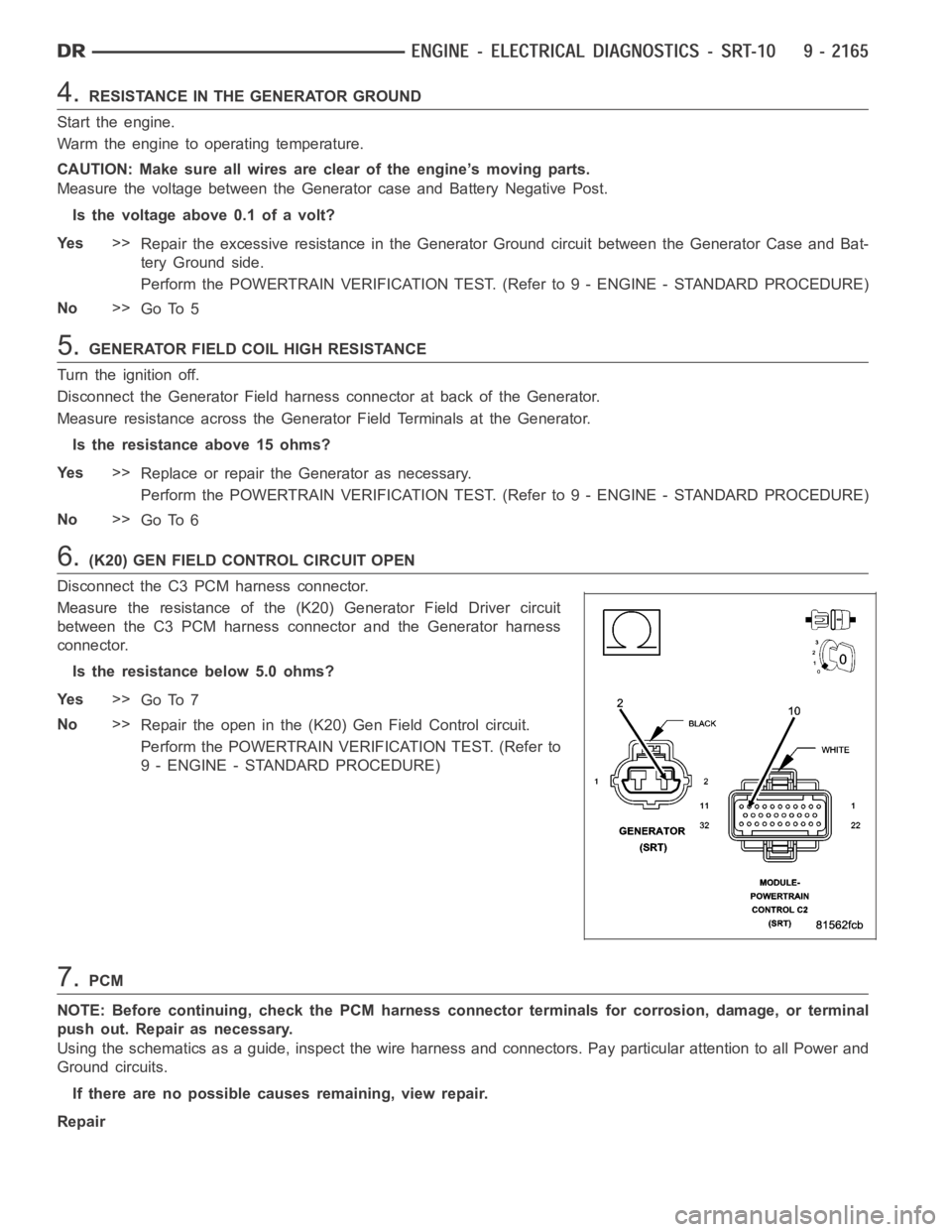
6.(K20) GEN FIELD CONTROL CIRCUIT OPEN
Disconnect the C3 PCM harness connector.
Measure the resistance of the (K20) Generator Field Driver circuit
between the C3 PCM harness connector and the Generator harness
connector.
Is the resistance below 5.0 ohms?
Ye s>>
Go To 7
No>>
Repair the open in the (K20) Gen Field Control circuit.
Perform the POWERTRAIN VERIFICATION TEST. (Refer to
9 - ENGINE - STANDARD PROCEDURE)
7.PCM
NOTE: Before continuing, check the PCM harness connector terminals for corrosion, damage, or terminal
push out. Repair as necessary.
Using the schematics as a guide, inspect the wire harness and connectors. Pay particular attention to all Power and
Ground circuits.
If there are no possible causes remaining, view repair.
Repair