Page 1448 of 5267
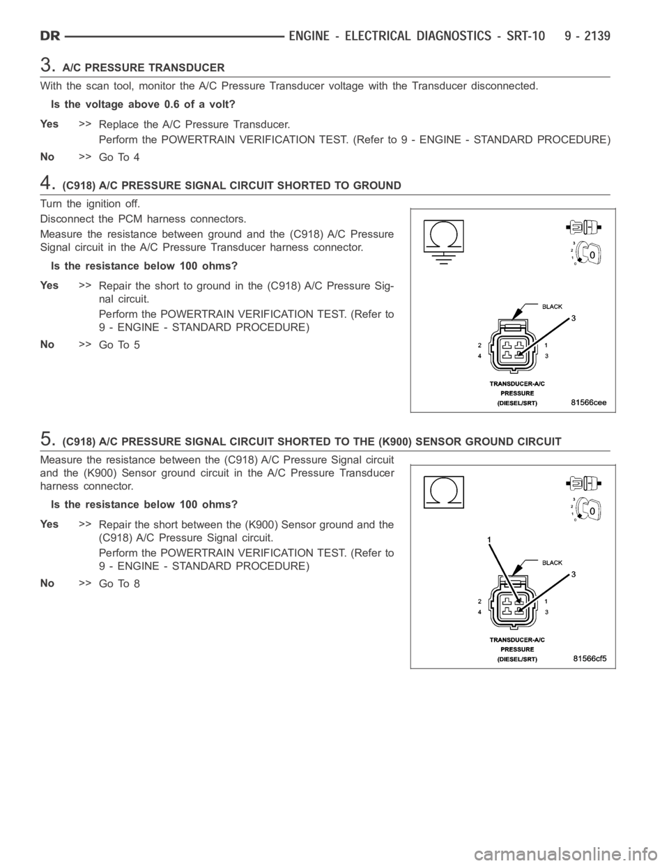
3.A/C PRESSURE TRANSDUCER
With the scan tool, monitor the A/C Pressure Transducer voltage with the Transducer disconnected.
Is the voltage above 0.6 of a volt?
Ye s>>
Replace the A/C Pressure Transducer.
Perform the POWERTRAIN VERIFICATION TEST. (Refer to 9 - ENGINE - STANDARD PROCEDURE)
No>>
Go To 4
4.(C918) A/C PRESSURE SIGNAL CIRCUIT SHORTED TO GROUND
Turn the ignition off.
Disconnect the PCM harness connectors.
Measure the resistance between ground and the (C918) A/C Pressure
Signal circuit in the A/C Pressure Transducer harness connector.
Istheresistancebelow100ohms?
Ye s>>
Repair the short to ground in the (C918) A/C Pressure Sig-
nal circuit.
Perform the POWERTRAIN VERIFICATION TEST. (Refer to
9 - ENGINE - STANDARD PROCEDURE)
No>>
Go To 5
5.(C918) A/C PRESSURE SIGNAL CIRCUIT SHORTED TO THE (K900) SENSOR GROUND CIRCUIT
Measure the resistance between the (C918) A/C Pressure Signal circuit
and the (K900) Sensor ground circuit in the A/C Pressure Transducer
harness connector.
Istheresistancebelow100ohms?
Ye s>>
Repair the short between the (K900) Sensor ground and the
(C918) A/C Pressure Signal circuit.
Perform the POWERTRAIN VERIFICATION TEST. (Refer to
9 - ENGINE - STANDARD PROCEDURE)
No>>
Go To 8
Page 1449 of 5267
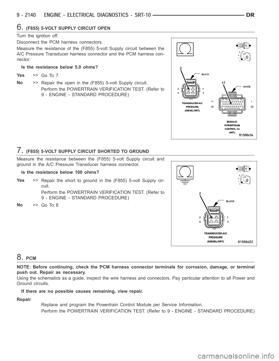
6.(F855) 5-VOLT SUPPLY CIRCUIT OPEN
Turn the ignition off.
Disconnect the PCM harness connectors.
Measure the resistance of the (F855) 5-volt Supply circuit between the
A/C Pressure Transducer harness connector and the PCM harness con-
nector.
Is the resistance below 5.0 ohms?
Ye s>>
Go To 7
No>>
Repair the open in the (F855) 5-volt Supply circuit.
Perform the POWERTRAIN VERIFICATION TEST. (Refer to
9 - ENGINE - STANDARD PROCEDURE)
7.(F855) 5-VOLT SUPPLY CIRCUIT SHORTED TO GROUND
Measure the resistance between the (F855) 5-volt Supply circuit and
ground in the A/C Pressure Transducer harness connector.
Istheresistancebelow100ohms?
Ye s>>
Repair the short to ground in the (F855) 5-volt Supply cir-
cuit.
Perform the POWERTRAIN VERIFICATION TEST. (Refer to
9 - ENGINE - STANDARD PROCEDURE)
No>>
Go To 8
8.PCM
NOTE: Before continuing, check the PCM harness connector terminals for corrosion, damage, or terminal
push out. Repair as necessary.
Using the schematics as a guide, inspect the wire harness and connectors. Pay particular attention to all Power and
Ground circuits.
If there are no possible causes remaining, view repair.
Repair
Replace and program the Powertrain Control Module per Service Information.
Perform the POWERTRAIN VERIFICATION TEST. (Refer to 9 - ENGINE - STANDARD PROCEDURE)
Page 1451 of 5267
When Monitored:
With the ignition key on and the engine running over 1500 RPM after 25 seconds.
Set Condition:
When the PCM regulates the generator field and there are no detected field problems, but the voltage output
does not increase.
Possible Causes
BATTERY TEMPERATURE SENSOR
RESISTANCE IN THE BATTERY POSITIVE CIRCUIT
(K125) GENERATOR FIELD SOURCE CIRCUIT OPEN
RESISTANCE IN THE GENERATOR GROUND
(K125) GENERATOR FIELD SOURCE CIRCUIT SHORTED TO GROUND
(K20) GENERATOR FIELD CONTROL CIRCUIT OPEN
RESISTANCE IN THE GENERATOR FIELD COIL
PCM
Always perform the Pre-Diagnostic Troubleshooting procedure before proceeding. (Refer to 9 - ENGINE -
DIAGNOSIS AND TESTING)
Diagnostic Test
1.CHARGING VOLTAGE BELOW 15.1 VOLTS
Turn the ignition off.
NOTE: Battery must be fully charged and capable of passing a battery load test.
NOTE: Generator Belt tension and condition must be checked before continuing.
NOTE: Inspect the vehicle for any aftermarket accessories that may exceedthe maximum Generator output.
WARNING: When the engine is operating, do not stand in direct line of the fan. Do not put your hands near
the pulley, belts, or fan. Do no wear loose clothing.
Start the engine.
Record all DTCs and the related Freeze Frame data.
With the scan tool, read the target charging voltage.
Is the target charging voltage above 15.1 volts?
Ye s>>
Refer to the INTERMITTENT CONDITION Diagnostic Procedure.
Perform the POWERTRAIN VERIFICATION TEST. (Refer to 9 - ENGINE - STANDARD PROCEDURE)
No>>
Go To 2
2.BATTERY TEMPERATURE SENSOR
Turn the ignition off.
NOTE: Generator Belt tension and condition must be checked before continuing.
Start the engine.
Allow the engine to reach normal operating temperature.
With the scan tool in sensors, read the Battery Temp Sensor value.
Using a Thermometer, measure under hood temperature.
Is the temperature within 10° F of Battery temperature?
Ye s>>
Go To 3
No>>
Replace the Battery Temperature Sensor.
Perform the POWERTRAIN VERIFICATION TEST. (Refer to 9 - ENGINE - STANDARD PROCEDURE)
Page 1452 of 5267
3.HIGH RESISTANCE IN THE BATTERY POSITIVE CIRCUIT
Ignition on, engine not running.
Measure the voltage between the Generator B+ Terminal and the Battery Positive Post.
WARNING: When the engine is operating, do not stand in direct line of the fan. Do not put your hands near
the pulley, belts, or fan. Do no wear loose clothing.
CAUTION: Make sure all wires are clear of the engine’s moving parts.
Start the engine.
Is the voltage above 0.4 of a volt?
Ye s>>
Repair the excessive resistance in the Battery Positive circuit between the Generator and Battery.
Perform the POWERTRAIN VERIFICATION TEST. (Refer to 9 - ENGINE - STANDARD PROCEDURE)
No>>
Go To 4
4.RESISTANCE IN THE GENERATOR GROUND
Start the engine.
WARNING: When the engine is operating, do not stand in direct line of the fan. Do not put your hands near
the pulley, belts, or fan. Do no wear loose clothing.
Warm the engine to operating temperature.
CAUTION: Make sure all wires are clear of the engine’s moving parts.
Measure the voltage between the Generator case and Battery Negative Post.
Is the voltage above 0.1 of a volt?
Ye s>>
Repair the excessive resistance in the Generator Ground circuit between the Generator Case and Bat-
tery Negative side.
Perform the POWERTRAIN VERIFICATION TEST. (Refer to 9 - ENGINE - STANDARD PROCEDURE)
No>>
Go To 5
5.(K125) GEN FIELD SOURCE CIRCUIT OPEN
Ignition on, engine not running.
Carefully inspect all connectors for corrosion or spread terminals before continuing.
With the scan tool actuate the Generator Field Driver.
While backprobing, measure the voltage on the (K125) Generator Field SourcecircuitatbackofGenerator.
Is the voltage above 10.0 volts?
Ye s>>
Go To 6
No>>
Repair the open in the (K125) Generator Field Source circuit.
Perform the POWERTRAIN VERIFICATION TEST. (Refer to 9 - ENGINE - STANDARD PROCEDURE)
Page 1453 of 5267
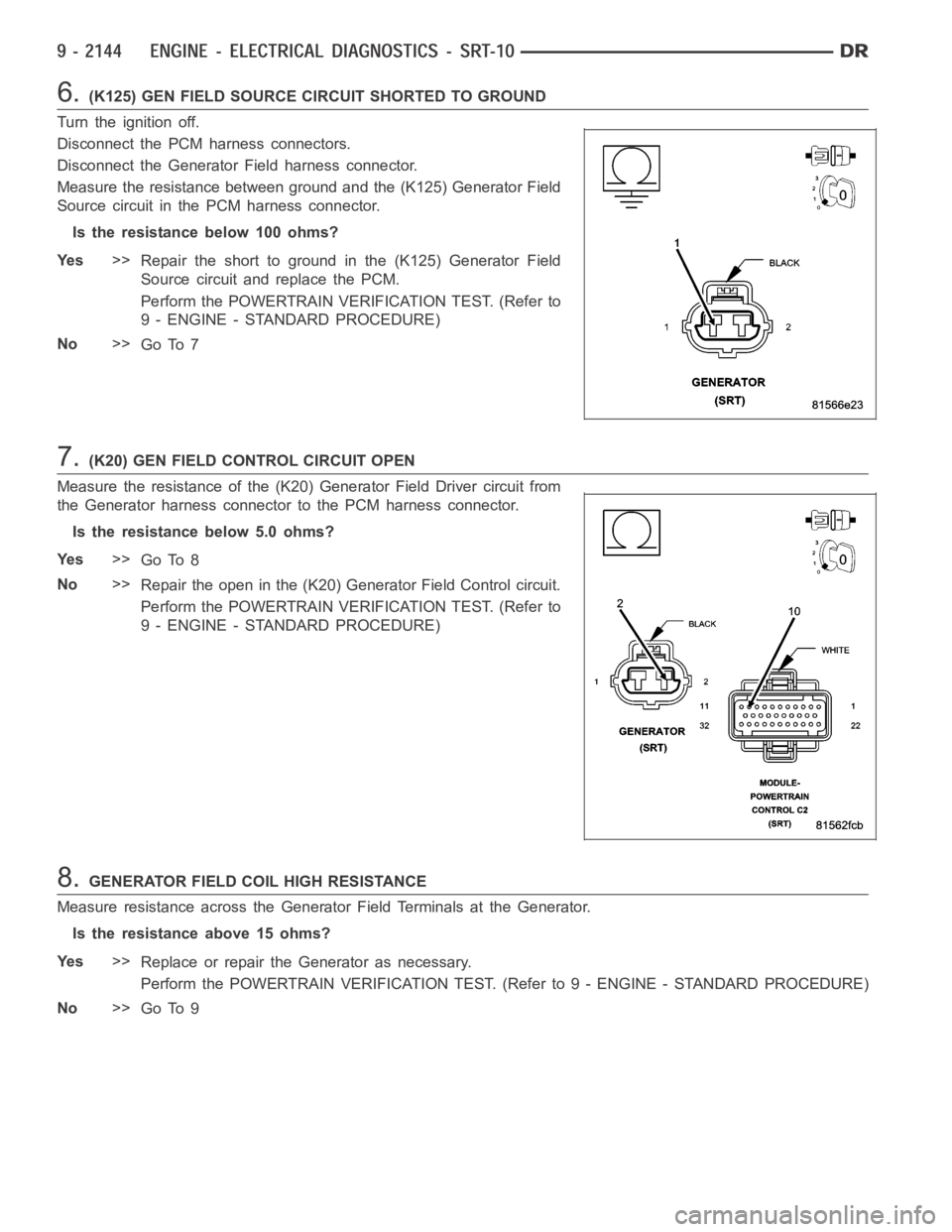
6.(K125) GEN FIELD SOURCE CIRCUIT SHORTED TO GROUND
Turn the ignition off.
Disconnect the PCM harness connectors.
Disconnect the Generator Field harness connector.
Measure the resistance between ground and the (K125) Generator Field
Source circuit in the PCM harness connector.
Istheresistancebelow100ohms?
Ye s>>
Repair the short to ground in the (K125) Generator Field
Source circuit and replace the PCM.
Perform the POWERTRAIN VERIFICATION TEST. (Refer to
9 - ENGINE - STANDARD PROCEDURE)
No>>
Go To 7
7.(K20) GEN FIELD CONTROL CIRCUIT OPEN
Measure the resistance of the (K20) Generator Field Driver circuit from
the Generator harness connector to the PCM harness connector.
Is the resistance below 5.0 ohms?
Ye s>>
Go To 8
No>>
Repair the open in the (K20) Generator Field Control circuit.
Perform the POWERTRAIN VERIFICATION TEST. (Refer to
9 - ENGINE - STANDARD PROCEDURE)
8.GENERATOR FIELD COIL HIGH RESISTANCE
Measure resistance across the Generator Field Terminals at the Generator.
Is the resistance above 15 ohms?
Ye s>>
Replace or repair the Generator as necessary.
Perform the POWERTRAIN VERIFICATION TEST. (Refer to 9 - ENGINE - STANDARD PROCEDURE)
No>>
Go To 9
Page 1456 of 5267
When Monitored:
With the ignition on.
Set Condition:
The PCM has not received an expected Cluster Status Bus message from the instrument cluster within the last
20 seconds.
Possible Causes
(D25) OPEN BETWEEN PCM AND CLUSTER
(D25) SHORTED BETWEEN PCM AND CLUSTER
CLUSTER
PCM
Always perform the Pre-Diagnostic Troubleshooting procedure before proceeding. (Refer to 9 - ENGINE -
DIAGNOSIS AND TESTING)
Diagnostic Test
1.NO CLUSTER BUS MESSAGE
Ignition on, engine not running.
With the scan tool, erase DTCs.
Cycle the ignition key on and off several times.
With the scan tool, read DTCs.
Does the DTC reset?
Ye s>>
Go To 2
No>>
Refer to the INTERMITTENT CONDITION Diagnostic Procedure.
Perform the POWERTRAIN VERIFICATION TEST. (Refer to 9 - ENGINE - STANDARD PROCEDURE)
2.COMMUNICATE WITH CLUSTER
Ignition on, engine not running.
With the scan tool, attempt to communicate with the Instrument cluster.
Can communication be established with the Instrument Cluster?
Ye s>>
Go To 3
No>>
Refer to the Communication Category of the Body Diagnostic Manual and perform the appropriate
symptom related to no communication with cluster.
Perform the POWERTRAIN VERIFICATION TEST. (Refer to 9 - ENGINE - STANDARD PROCEDURE)
3.INSTRUMENT CLUSTER OPERATION
Start the engine
Allow the engine to idle.
Is the correct engine speed display in the instrument cluster (Tach)?
Ye s>>
Replace and program the Powertrain Control Module per Service Information.
Perform the POWERTRAIN VERIFICATION TEST. (Refer to 9 - ENGINE - STANDARD PROCEDURE)
No>>
Refer to the Instrument Category in the Body Diagnostic Manual and performthe appropriate symptom.
Perform the POWERTRAIN VERIFICATION TEST. (Refer to 9 - ENGINE - STANDARD PROCEDURE)
Page 1458 of 5267
When Monitored:
With the ignition on. Battery voltage greater than 10.4 volts.
Set Condition:
No BUS messages recieved from the BCM for 20 seconds.
Possible Causes
(D25) PCI BUS CIRCUIT OPEN
PCM
Always perform the Pre-Diagnostic Troubleshooting procedure before proceeding. (Refer to 9 - ENGINE -
DIAGNOSIS AND TESTING)
Diagnostic Test
1.DTC RESET
Ignition on, engine not running.
With the scan tool, erase DTCs.
Cycle the ignition key on and off several times. Leaving the ignition on forat least 20 seconds.
With the scan tool, read DTCs.
Does the DTC reset?
Ye s>>
Go To 2
No>>
Refer to the INTERMITTENT CONDITION Diagnostic Procedure.
Perform the POWERTRAIN VERIFICATION TEST. (Refer to 9 - ENGINE - STANDARD PROCEDURE)
2.COMMUNICATE WITH FCM
With the scan tool, attempt to communicate with the FCM.
Can communication be established with the BCM?
Ye s>>
Go To 3
No>>
Refer to the Communication Category and perform the appropriate symptom related to no communica-
tion with FCM.
Perform the POWERTRAIN VERIFICATION TEST. (Refer to 9 - ENGINE - STANDARD PROCEDURE)
Page 1459 of 5267
3.(D25) PCI BUS CIRCUIT OPEN
Turn the ignition off.
Disconnect the C3 PCM harness connector.
Disconnect the FCM harness connector.
NOTE: Inspect the PCI Bus terminal at both the PCM connectors
and the FCM connectors. Check for corrosion, damage or terminal
push out.
Measure the resistance of the (D25) PCI BUS circuit between the C3
PCM harness connector and the FCM harness connector.
Is the resistance below 5.0 ohms?
Ye s>>
Replace and program the Powertrain Control Module per
Service Information.
Perform the POWERTRAIN VERIFICATION TEST. (Refer to
9 - ENGINE - STANDARD PROCEDURE)
No>>
Repair the open in the (D25) PCI BUS circuit.
Perform the POWERTRAIN VERIFICATION TEST. (Refer to
9 - ENGINE - STANDARD PROCEDURE)