Page 1260 of 2893
����
���� ����
����
14-336Shafts and Clutches
1st, 2nd, and 3rd Clutch Reassembly (cont’d)
07LAE-PX40000
AB
C A
B
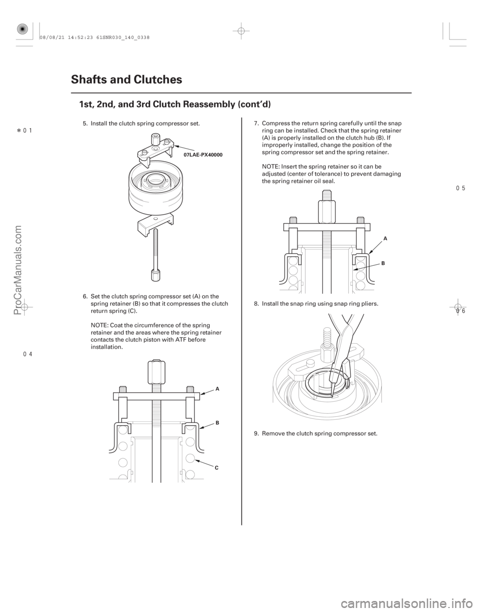
5. Install the clutch spring compressor set.
6. Set the clutch spring compressor set (A) on the spring retainer (B) so that it compresses the clutch
return spring (C).
NOTE: Coat the circumference of the spring
retainer and the areas where the spring retainer
contacts the clutch piston with ATF before
installation. 7. Compress the return spring carefully until the snap
ring can be installed. Check that the spring retainer
(A) is properly installed on the clutch hub (B). If
improperly installed, change the position of the
spring compressor set and the spring retainer.
NOTE: Insert the spring retainer so it can be
adjusted (center of tolerance) to prevent damaging
the spring retainer oil seal.
8. Install the snap ring using snap ring pliers.
9. Remove the clutch spring compressor set.
08/08/21 14:52:23 61SNR030_140_0338
ProCarManuals.com
DYNOMITE -2009-
Page 1261 of 2893
�������
����
14-337
Improperly installed:
Properly installed:
A B
B
A A
B
CD
E
A
B G
E
D
C F
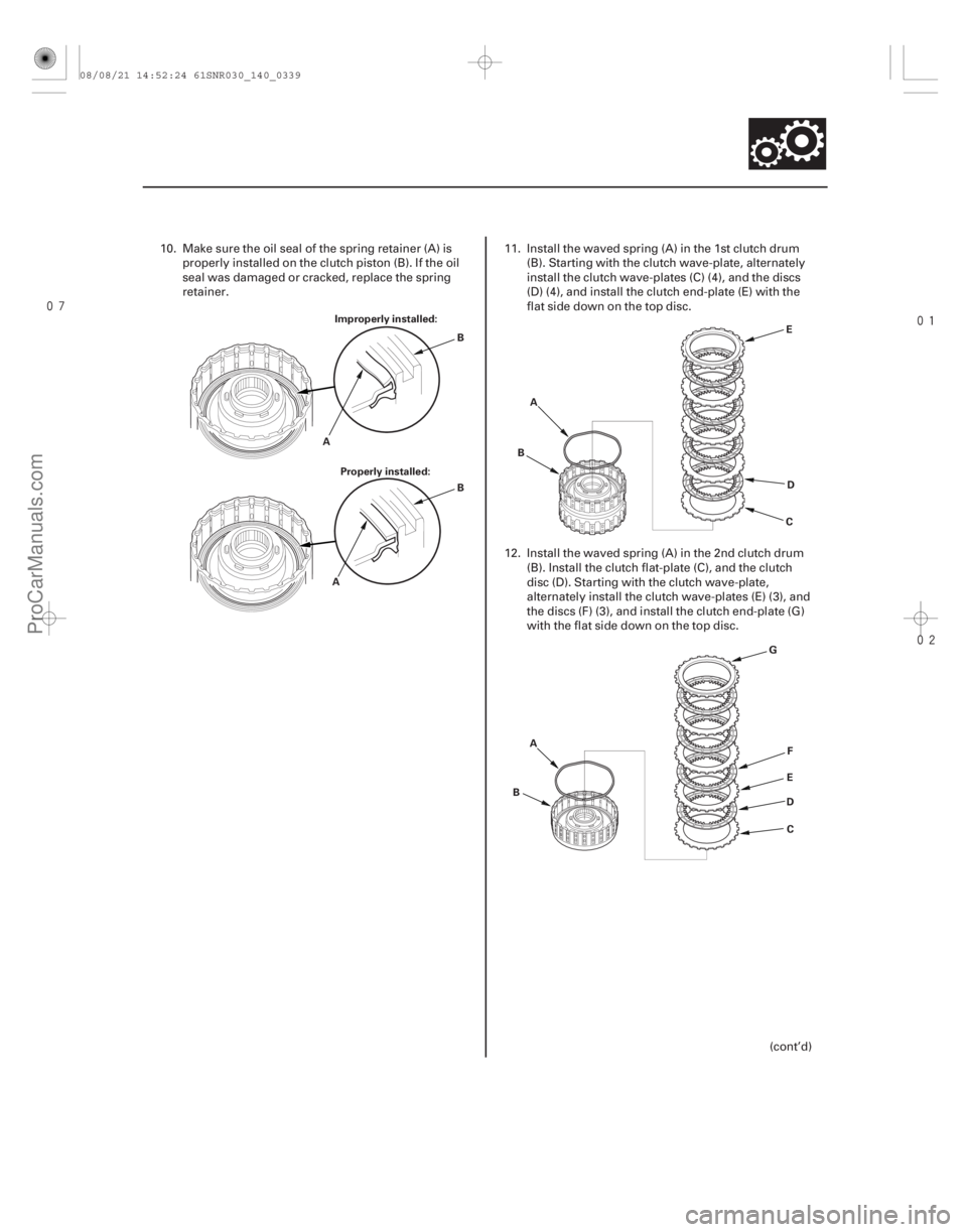
10. Make sure the oil seal of the spring retainer (A) is
properly installed on the clutch piston (B). If the oil
seal was damaged or cracked, replace the spring
retainer. 11. Install the waved spring (A) in the 1st clutch drum
(B). Starting with the clutch wave-plate, alternately
install the clutch wave-plates (C) (4), and the discs
(D) (4), and install the clutch end-plate (E) with the
flat side down on the top disc.
12. Install the waved spring (A) in the 2nd clutch drum (B). Install the clutch flat-plate (C), and the clutch
disc (D). Starting with the clutch wave-plate,
alternately install the clutch wave-plates (E) (3), and
the discs (F) (3), and install the clutch end-plate (G)
with the flat side down on the top disc.
(cont’d)
08/08/21 14:52:24 61SNR030_140_0339
ProCarManuals.com
DYNOMITE -2009-
Page 1262 of 2893
���
�������
�(�#�'�������
���
�����
�
���
�������
�!�����)���� Special Tools Required
14-33814-338 Shafts and Clutches
1st, 2nd, and 3rd Clutch
Reassembly (cont’d)
4thand5thClutchReassembly
A
B E
D
C F
G
A
B
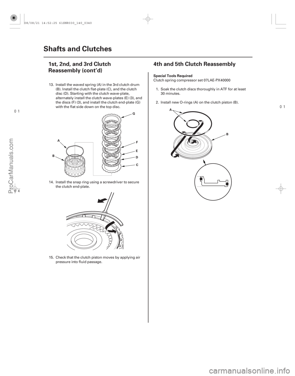
13. Install the waved spring (A) in the 3rd clutch drum(B). Install the clutch flat-plate (C), and the clutch
disc (D). Starting with the clutch wave-plate,
alternately install the clutch wave-plates (E) (3), and
the discs (F) (3), and install the clutch end-plate (G)
with the flat side down on the top disc.
14. Install the snap ring using a screwdriver to secure the clutch end-plate.
15. Check that the clutch piston moves by applying air pressure into fluid passage. Clutch spring compressor set 07LAE-PX40000
1. Soak the clutch discs thoroughly in ATF for at least 30 minutes.
2. Install new O-rings (A) on the clutch piston (B).
08/08/21 14:52:25 61SNR030_140_0340
ProCarManuals.com
DYNOMITE -2009-
Page 1263 of 2893
���
�������
�(�#�'�������
���
�����
�
���
�������
�!�����)���� Special Tools Required
14-33814-338 Shafts and Clutches
1st, 2nd, and 3rd Clutch
Reassembly (cont’d)
4thand5thClutchReassembly
A
B E
D
C F
G
A
B
13. Install the waved spring (A) in the 3rd clutch drum(B). Install the clutch flat-plate (C), and the clutch
disc (D). Starting with the clutch wave-plate,
alternately install the clutch wave-plates (E) (3), and
the discs (F) (3), and install the clutch end-plate (G)
with the flat side down on the top disc.
14. Install the snap ring using a screwdriver to secure the clutch end-plate.
15. Check that the clutch piston moves by applying air pressure into fluid passage. Clutch spring compressor set 07LAE-PX40000
1. Soak the clutch discs thoroughly in ATF for at least 30 minutes.
2. Install new O-rings (A) on the clutch piston (B).
08/08/21 14:52:25 61SNR030_140_0340
ProCarManuals.com
DYNOMITE -2009-
Page 1264 of 2893
����
��������
���
14-339
A
B
C B
A 07LAE-PX40000
A
B
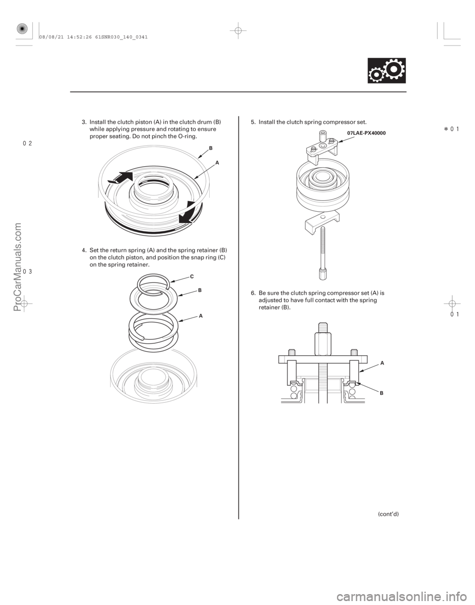
3. Install the clutch piston (A) in the clutch drum (B) while applying pressure and rotating to ensure
proper seating. Do not pinch the O-ring.
4. Set the return spring (A) and the spring retainer (B) on the clutch piston, and position the snap ring (C)
on the spring retainer. 5. Install the clutch spring compressor set.
6. Be sure the clutch spring compressor set (A) is
adjusted to have full contact with the spring
retainer (B).
(cont’d)
08/08/21 14:52:26 61SNR030_140_0341
ProCarManuals.com
DYNOMITE -2009-
Page 1265 of 2893
����
��������
����
14-340Shafts and Clutches
4thand5thClutchReassembly(cont’d)
E
D
C
B
A
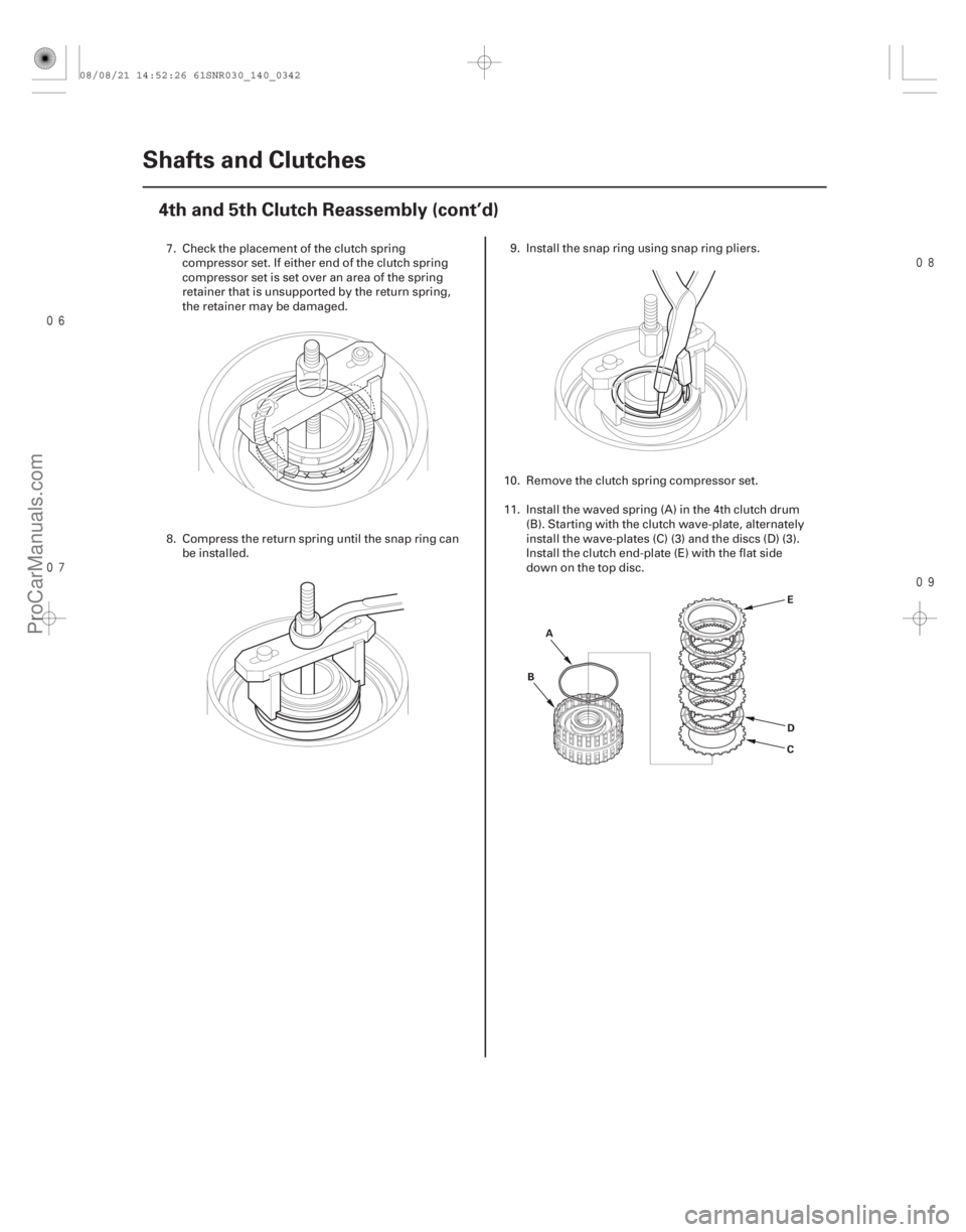
7. Check the placement of the clutch spring
compressor set. If either end of the clutch spring
compressor set is set over an area of the spring
retainer that is unsupported by the return spring,
the retainer may be damaged.
8. Compress the return spring until the snap ring can be installed. 9. Install the snap ring using snap ring pliers.
10. Remove the clutch spring compressor set.
11. Install the waved spring (A) in the 4th clutch drum (B). Starting with the clutch wave-plate, alternately
install the wave-plates (C) (3) and the discs (D) (3).
Install the clutch end-plate (E) with the flat side
downonthetopdisc.
08/08/21 14:52:26 61SNR030_140_0342
ProCarManuals.com
DYNOMITE -2009-
Page 1266 of 2893
�
��
�
�
14-341
E
D
C
B
A
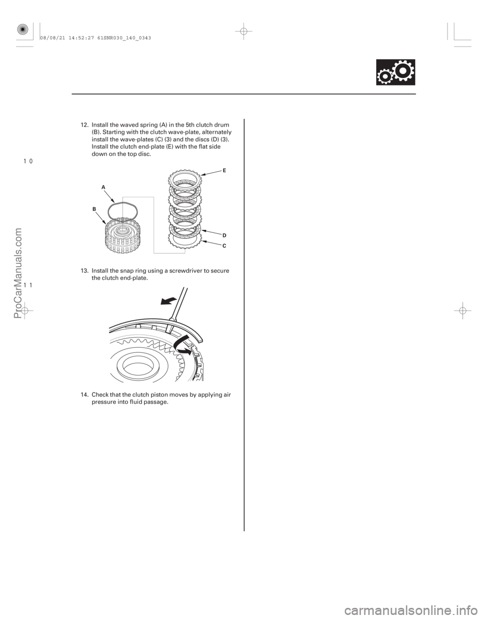
12. Install the waved spring (A) in the 5th clutch drum
(B). Starting with the clutch wave-plate, alternately
install the wave-plates (C) (3) and the discs (D) (3).
Install the clutch end-plate (E) with the flat side
downonthetopdisc.
13. Install the snap ring using a screwdriver to secure the clutch end-plate.
14. Check that the clutch piston moves by applying air pressure into fluid passage.
08/08/21 14:52:27 61SNR030_140_0343
ProCarManuals.com
DYNOMITE -2009-
Page 1274 of 2893
����
�(�#�'�������
���
�����
�������������
� �����)����
Exploded View
14-349
Transmission End Cover
End Cover Installation
A/T CLUTCH PRESSURE
CONTROL SOLENOID
VALVES B and C
TRANSMISSION RANGE
SWITCH COVER
TRANSMISSION
RANGE SWITCH 6x1.0mm
6x1.0mm
28 N·m
(2.9 kgf·m, 21 lbf·ft)
6x1.0mm
TRANSMISSION
END COVER
6x1.0mm
12 Bolts
28 N·m
(2.9 kgf·m, 21 lbf·ft)CONICAL SPRING
WASHERS
PARK GEAR
STOP SHAFT PARK
LEVER STOP
LOCK WASHER
14 N·m
(1.4 kgf·m,
10 lbf·ft)
PARK PAWL
PARK PAWL
SPRING PARK PAWL
SHAFT
PARK LEVER
SPRING MAINSHAFT
IDLER GEAR
TRANSMISSION
END COVER GASKET HARNESS CLAMP
BRACKETS
6x1.0mm
ATF JOINT
PIPES
ATF JOINT PIPES
ATF PIPE 6x1.0mm
A/T CLUTCH PRESSURE
CONTROL SOLENOID
VALVE A
Torque Specifications
6 x 1.0 mm: 12 N·m (1.2 kgf·m, 8.7 lbf·ft)
28 N·m
(2.9 kgf·m,
21 lbf·ft)
PARK
LEVER
(cont’d)
Replace.
Replace. Replace.
08/08/21 14:52:34 61SNR030_140_0351
ProCarManuals.com
DYNOMITE -2009-