Page 1209 of 2893
���
�(�#�'�������
���
�����
�������������
� �����)���� Special Tools Required
14-290Transmission End Cover
End Cover Removal
A
D
E
I J
K
L
M
N O
P Q
R S
T F
G
H F
R S
J
F ED
F
B, C
Mainshaft holder 07GAB-PF50101
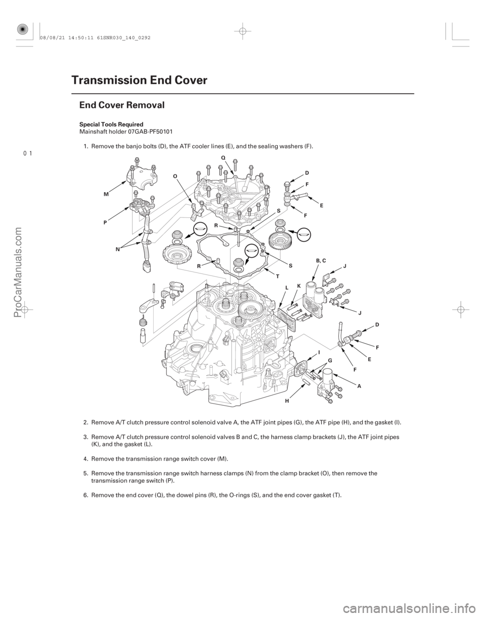
1. Remove the banjo bolts (D), the ATF cooler lines (E), and the sealing washers (F).
2. Remove A/T clutch pressure control solenoid valve A, the ATF joint pipes (G), the ATF pipe (H), and the gasket (I).
3. Remove A/T clutch pressure control solenoid valves B and C, the harness clamp brackets (J), the ATF joint pipes (K), and the gasket (L).
4. Remove the transmission range switch cover (M).
5. Remove the transmission range switch harness clamps (N) from the clamp bracket (O), then remove the transmission range switch (P).
6. Remove the end cover (Q), the dowel pins (R), the O-rings (S), and the end cover gasket (T).
08/08/21 14:50:11 61SNR030_140_0292
ProCarManuals.com
DYNOMITE -2009-
Page 1213 of 2893
���
�(�#�'�������
���
�����
�����
�����
��� �����)����
14-294Transmission End Cover
ATF Feed Pipe Replacement
A
C
G
F
E
D
A
C
F
G
B B
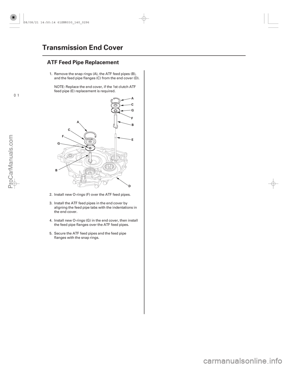
1. Remove the snap rings (A), the ATF feed pipes (B),
and the feed pipe flanges (C) from the end cover (D).
NOTE: Replace the end cover, if the 1st clutch ATF
feed pipe (E) replacement is required.
2. Install new O-rings (F) over the ATF feed pipes.
3. Install the ATF feed pipes in the end cover by aligning the feed pipe tabs with the indentations in
the end cover.
4. Install new O-rings (G) in the end cover, then install the feed pipe flanges over the ATF feed pipes.
5. Secure the ATF feed pipes and the feed pipe flanges with the snap rings.
08/08/21 14:50:14 61SNR030_140_0296
ProCarManuals.com
DYNOMITE -2009-
Page 1234 of 2893
����
14-312Shafts and Clutches
Mainshaft Disassembly, Inspection, and Reassembly
LOCKNUT (FLANGE NUT)
24x1.25mm
CONICAL SPRING
WASHER
IDLER GEAR
TR")
����
�(�#�'�������
���
�����
�
�������������"�����)����
14-312Shafts and Clutches
Mainshaft Disassembly, Inspection, and Reassembly
LOCKNUT (FLANGE NUT)
24x1.25mm
CONICAL SPRING
WASHER
IDLER GEAR
TRANSMISSION
HOUSING BEARING
THRUST NEEDLE BEARING
4TH GEAR
NEEDLE BEARING
THRUST NEEDLE BEARING
4TH GEAR COLLAR
4TH/5TH CLUTCH
O-RINGS THRUST WASHER, 41 x 68 mm
NEEDLE BEARING THRUST NEEDLE BEARING 5TH GEAR
THRUST NEEDLE BEARING
SEALING RINGS,
29 mm
NEEDLE BEARING
SET RING
1. Inspect the thrust needle bearing and the needle bearing for galling and r ough movement.
2. Inspect the splines for excessive wear and damage.
3. Check the shaft bearing surface for scoring and excessive wear.
4. Before installing new O-rings, wrap the shaft splines with tape to prevent the O-ring damage.
5. Lubricate all parts with ATF during assembly.
6. Install the conical spring washer and the 41 x 68 mm thrust washer in the direction shown.
7. Replace the locknut and the conical spring washer with new ones when assembling the transmission.
8. Check the clearance of 5th gear (see page 14-313).
Replace. Replace.
Replace. Selective part
Replace.
08/08/21 14:51:18 61SNR030_140_0314
ProCarManuals.com
DYNOMITE -2009-
Page 1235 of 2893
���
����
����
�(�#�'�����������
�����
�
�����������
�"�����)���� �µ�µ
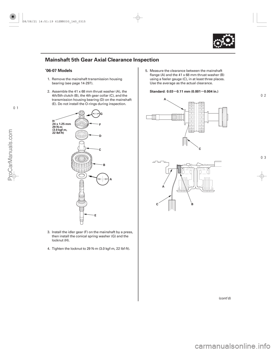
’06-07 Models
Standard: 0.03 0.11 mm (0.001 0.004 in.)
14-313
Mainshaft 5th Gear Axial Clearance Inspection
H
24x1.25mm
29 N·m
(3.0 kgf·m,
22 lbf·ft)
G
F
D
C
B A
E C
A
B
C A
1. Remove the mainshaft transmission housing
bearing (see page 14-297).
2. Assemble the 41 x 68 mm thrust washer (A), the 4th/5th clutch (B), the 4th gear collar (C), and the
transmission housing bearing (D) on the mainshaft
(E). Do not install the O-rings during inspection.
3. Install the idler gear (F) on the mainshaft by a press, then install the conical spring washer (G) and the
locknut (H).
4. Tighten the locknut to 29 N·m (3.0 kgf·m, 22 lbf·ft). 5. Measure the clearance between the mainshaft
flange (A) and the 41 x 68 mm thrust washer (B)
using a feeler gauge (C), in at least three places.
Use the average as the actual clearance.
(cont’d)
08/08/21 14:51:19 61SNR030_140_0315
ProCarManuals.com
DYNOMITE -2009-
Page 1236 of 2893
����
THRUST WASHER, 41 x 68 mm
No. Part Number Thickness
’08-09 Models
14-31414-314Shafts and Clutches
Mainshaft 5th Gear Axial Clearance Inspe")
���
���
�(�#�'�����������
�����
�
�����������
�"�����)����
THRUST WASHER, 41 x 68 mm
No. Part Number Thickness
’08-09 Models
14-31414-314Shafts and Clutches
Mainshaft 5th Gear Axial Clearance Inspection (cont’d)
A
L
E
J
H
G
F
DC
B A
I K
6. If the clearance is out of standard, remove the
41 x 68 mm thrust washer and measure its
thickness (A).
7. Select and install a new thrust washer, then recheck.
1 90414-PRP-000 6.35 mm (0.250 in.)
2 90415-PRP-000 6.40 mm (0.252 in.)
3 90416-PRP-000 6.45 mm (0.254 in.)
4 90417-PRP-000 6.50 mm (0.256 in.)
5 90418-PRP-000 6.55 mm (0.258 in.)
6 90419-PRP-000 6.60 mm (0.260 in.)
8. After replacing the thrust washer, make sure the clearance is within standard.
9. Disassemble the shaft and gears.
10. Reinstall the bearing in the transmission housing (see page 14-298). 1. Remove the mainshaft transmission housing
bearing (see page 14-297).
2. Install the thrust needle bearing (A), 5th gear (B), the needle bearing (C), the thrust needle bearing
(D), the 41 x 68 mm thrust washer (E), the 4th/5th
clutch (F), the 4th gear collar (G), and the
transmission housing bearing (H) on the mainshaft
(I). Do not install the O-rings during inspection.
3. Install the idler gear (J) on the mainshaft by a press, then install the conical spring washer (K) and the
locknut (L).
4. Tighten the locknut to 29 N·m (3.0 kgf·m, 22 lbf·ft).
08/08/21 14:51:19 61SNR030_140_0316
ProCarManuals.com
DYNOMITE -2009-
Page 1238 of 2893
����
14-316Shafts and Clutches
Countershaft Disassembly, Inspection, and Reassembly
LOCKNUT (FLANGE NUT)
24x1.25mm
Left-hand threads
CONICAL SPRING
WA")
���
�(�#�'�������
���
�����
���������������"�����)����
14-316Shafts and Clutches
Countershaft Disassembly, Inspection, and Reassembly
LOCKNUT (FLANGE NUT)
24x1.25mm
Left-hand threads
CONICAL SPRING
WASHER
TRANSMISSION
HOUSING BEARING
4TH GEAR NEEDLE BEARING
PARK GEAR
REVERSE
SELECTOR
REVERSE GEAR
COUNTERSHAFT 3RD GEAR
5TH GEAR 1ST GEAR
2ND GEAR
REVERSE SELECTOR HUB
NEEDLE BEARING
COTTERS, 31 mm SET RING
COLLAR,
37x41x54.3mm COLLAR,
35x47x7.8mm
1. Inspect the needle bearing for galling and r
ough movement.
2. Inspect the splines for excessive wear and damage.
3. Check the shaft bearing surface for scoring and excessive wear.
4. Lubricate all parts with ATF during assembly.
5. Install the conical spring washer, the reverse selector, 35 x 47 x 7.8 mm collar, and all gears in the direction shown.
6. Replace the locknut and the conical spring washer with new ones when assembling the transmission. The countershaft locknut has left-hand threads.
7. Some reverse selector hubs and 3rd gear are press-fitted to the countershaft; special tools are needed to remove
them (see page 14-317) and to install them (see page 14-318).
Replace.
Replace.
08/08/21 14:51:21 61SNR030_140_0318
ProCarManuals.com
DYNOMITE -2009-
Page 1240 of 2893
���
����
�(�#�'�������
���
�����
�����
�������
� �����)����
Special Tools Required
14-318
Shafts and Clutches
Countershaft 3rd Gear and Reverse Selector Hub Installation
07746-0030100
A 07746-0030100
A
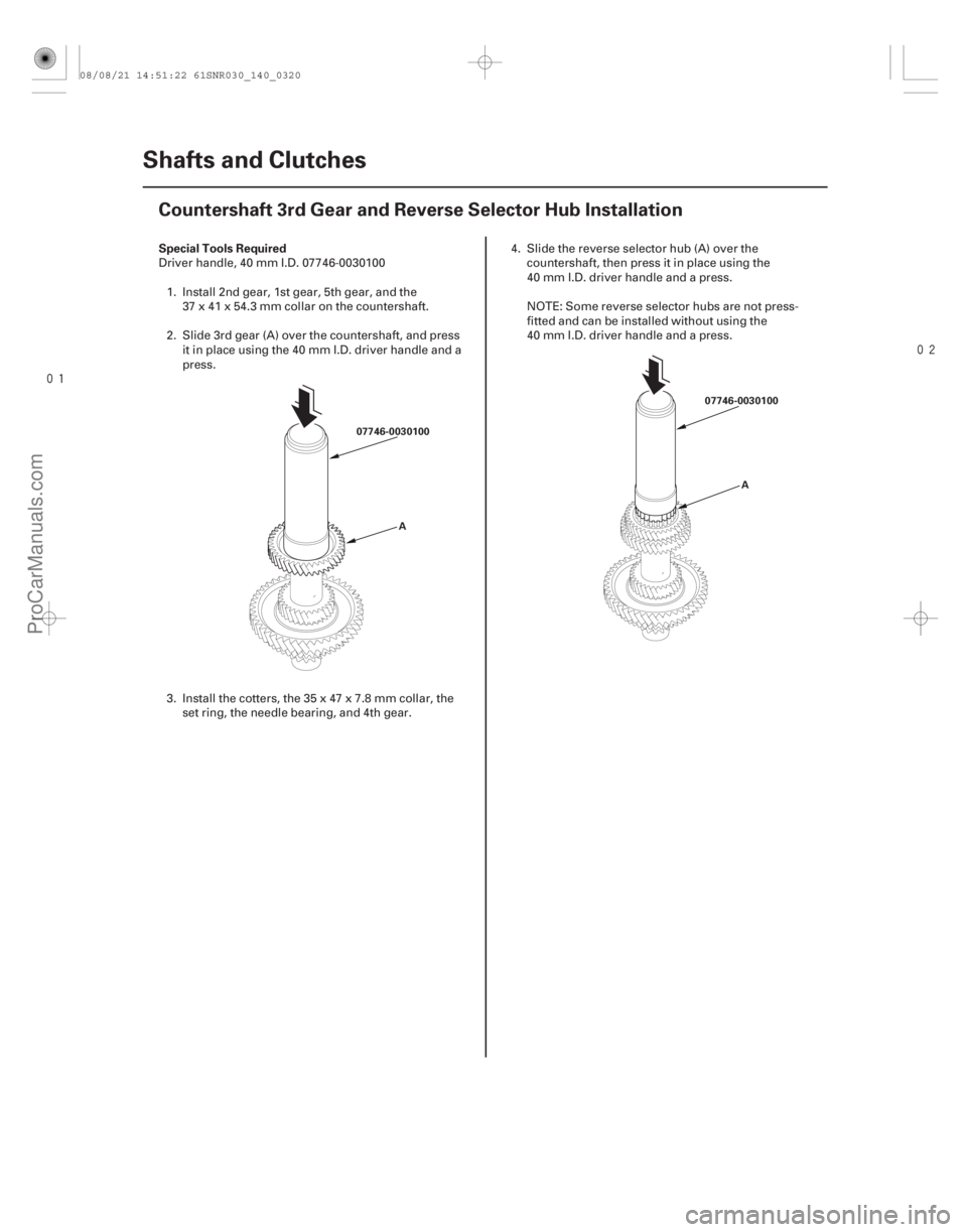
Driver handle, 40 mm I.D. 07746-00301001. Install 2nd gear, 1st gear, 5th gear, and the 37 x 41 x 54.3 mm collar on the countershaft.
2. Slide 3rd gear (A) over the countershaft, and press it in place using the 40 mm I.D. driver handle and a
press.
3. Install the cotters, the 35 x 47 x 7.8 mm collar, the set ring, the needle bearing, and 4th gear. 4. Slide the reverse selector hub (A) over the
countershaft, then press it in place using the
40 mm I.D. driver handle and a press.
NOTE: Some reverse selector hubs are not press-
fitted and can be installed without using the
40 mm I.D. driver handle and a press.
08/08/21 14:51:22 61SNR030_140_0320
ProCarManuals.com
DYNOMITE -2009-
Page 1241 of 2893
����
14-319
Secondary Shaft Disassembly, Inspection, and Reassembly
CONICAL
SPRING
WASHER
THRUST NEEDLE
BEARING
1ST GEAR TRANSMISSION
HOUSING BEARI")
����
�(�#�'�������
���
�����
�
�������������"�����)����
14-319
Secondary Shaft Disassembly, Inspection, and Reassembly
CONICAL
SPRING
WASHER
THRUST NEEDLE
BEARING
1ST GEAR TRANSMISSION
HOUSING BEARING
1ST/3RD CLUTCH O-RINGS THRUST WASHER,
40 x 51.5 mm
THRUST NEEDLE BEARING
2ND GEAR
NEEDLE BEARINGTHRUST NEEDLE BEARING IDLER GEAR
THRUST NEEDLE BEARING
SEALING RINGS,
29 mm
SET RING 3RD GEAR
SECONDARY SHAFT
THRUST NEEDLE
BEARING
NEEDLE BEARING
THRUST NEEDLE
BEARING
THRUST WASHER,
37x58mm
O-RINGS
2ND CLUTCH NEEDLE BEARING
3RD GEAR COLLAR
LOCKNUT (FLANGE NUT)
24x1.25mm
Left-hand threads
1. Inspect the thrust needle bearing and the needle bearing for galling and r
ough movement.
2. Inspect the splines for excessive wear and damage.
3. Check the shaft bearing surface for scoring and excessive wear.
4. Before installing new O-rings, wrap the shaft splines with tape to prevent O-ring damage.
5. Lubricate all parts with ATF during assembly.
6. Install the conical spring washer and the idler gear in the direction shown.
7. Replace the locknut and the conical spring washer with new ones when assembling the transmission. The locknut has left-hand threads.
8. Check the clearance of 2nd gear (see page 14-321) and 1st gear (see page 14-322).
Replace.
Replace. Selective part
Replace.
Replace. Selective part
Replace. Replace.
08/08/21 14:51:22 61SNR030_140_0321
ProCarManuals.com
DYNOMITE -2009-