Page 1252 of 2893
����
��������
����
14-328Shafts and Clutches
Clutch Disassembly (cont’d)
A
B
C
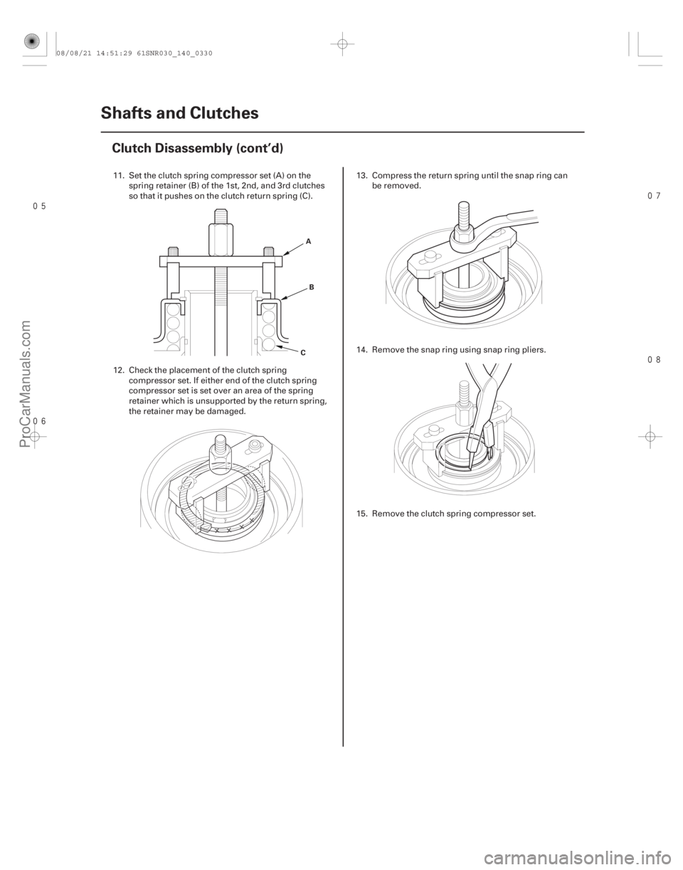
11. Set the clutch spring compressor set (A) on the spring retainer (B) of the 1st, 2nd, and 3rd clutches
so that it pushes on the clutch return spring (C).
12. Check the placement of the clutch spring compressor set. If either end of the clutch spring
compressor set is set over an area of the spring
retainer which is unsupported by the return spring,
the retainer may be damaged. 13. Compress the return spring until the snap ring can
be removed.
14. Remove the snap ring using snap ring pliers.
15. Remove the clutch spring compressor set.
08/08/21 14:51:29 61SNR030_140_0330
ProCarManuals.com
DYNOMITE -2009-
Page 1253 of 2893
����
�
�������
�����
14-329
A
B
C
A B D
B
C A
BA
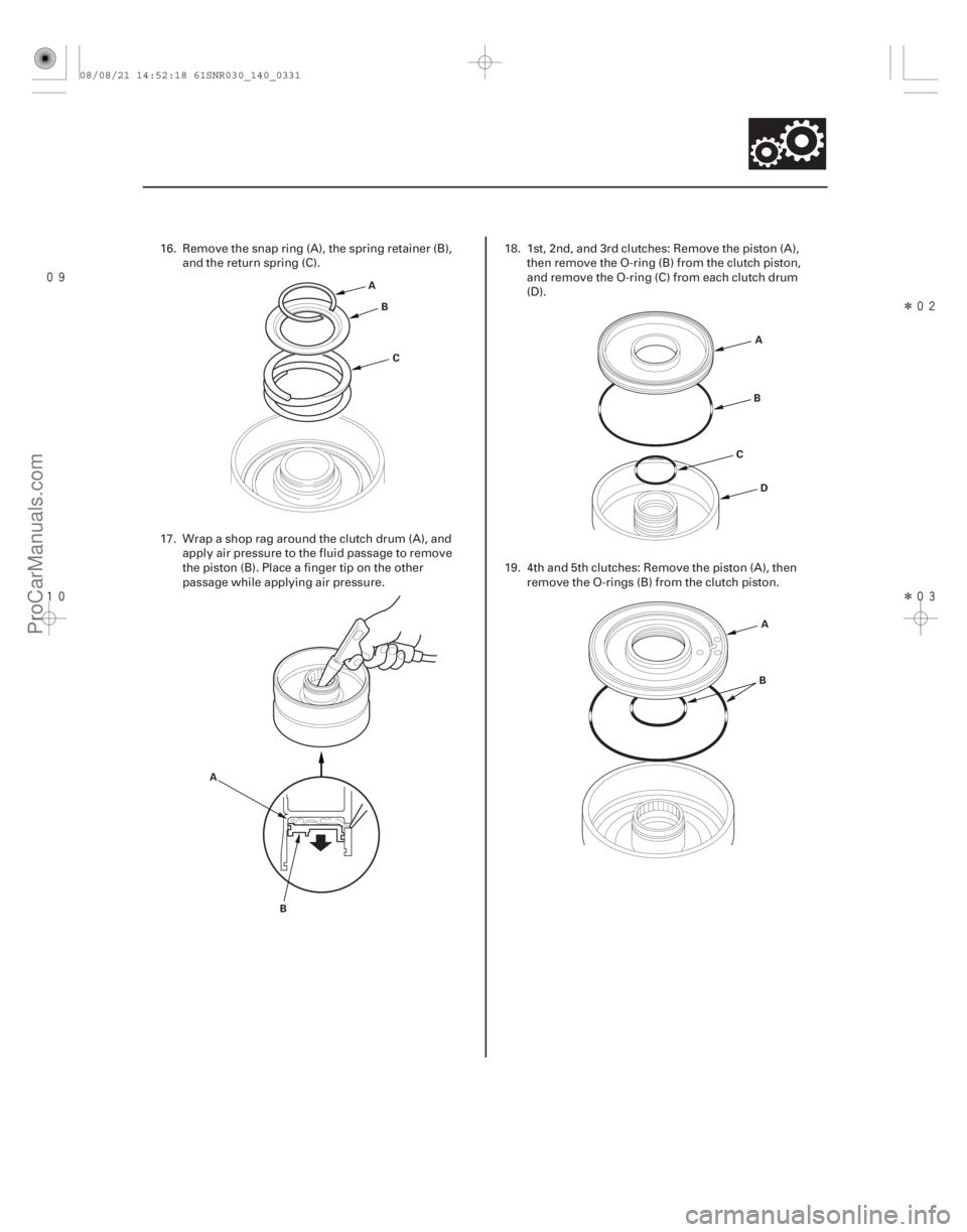
16. Remove the snap ring (A), the spring retainer (B),
and the return spring (C).
17. Wrap a shop rag around the clutch drum (A), and apply air pressure to the fluid passage to remove
the piston (B). Place a finger tip on the other
passage while applying air pressure. 18. 1st, 2nd, and 3rd clutches: Remove the piston (A),
then remove the O-ring (B) from the clutch piston,
and remove the O-ring (C) from each clutch drum
(D).
19. 4th and 5th clutches: Remove the piston (A), then remove the O-rings (B) from the clutch piston.
08/08/21 14:52:18 61SNR030_140_0331
ProCarManuals.com
DYNOMITE -2009-
Page 1254 of 2893
����Standard Thickness
Clutch Discs: 1.94 mm (0.076 in.)
Clutch Plates Standard Thickness:
1st Clutch (wave-plates): 2.0 mm (0.079 in.)
2nd Clutc")
���
�����(�#�'�������
���
�����
�
���
�������
�"�����)����Standard Thickness
Clutch Discs: 1.94 mm (0.076 in.)
Clutch Plates Standard Thickness:
1st Clutch (wave-plates): 2.0 mm (0.079 in.)
2nd Clutch Wave-plates: 2.0 mm (0.079 in.)
Flat-plate: 2.0 mm (0.079 in.)
3rd Clutch Wave-plates: 2.0 mm (0.079 in.) Flat-plates: 2.0 mm (0.079 in.)
4th Clutch (wave-plates): 2.3 mm (0.091 in.)
5th Clutch (wave-plates): 2.3 mm (0.091 in.)
14-330 Shafts and Clutches
Clutch Inspection
A
A
1. Inspect the 4th and 5th clutch pistons and the clutch piston check valves (A).
2. If the clutch piston check valve is loose or damaged, replace the clutch piston.
3. Check the spring retainer for wear and damage.
4. Check the oil seal (A) on the spring retainer of the 1st, 2nd, and 3rd clutches for wear, damage, and
peeling.
5. If the oil seal is worn, damaged, or peeling, replace the spring retainer. 6. Inspect the clutch discs, the clutch plates, and the
clutch end-plate for wear, damage, and
discoloration.
7. If the clutch discs are worn or damaged, replace them as a set. If the clutch discs are replaced,
inspect the clearance between the clutch end-plate
andthetopdisc.
8. If any plate is worn, damaged, or discolored, replace the damaged plate with a new plate, and
inspect the other wave-plates for a phase
difference. If the clutch plate is replaced, inspect
the clearance between the clutch end-plate and the
top disc.
9. If the clutch end-plate is worn, damaged, or discolored, inspect the clearance between the
clutch end-plate and the top disc, then replace the
clutch end-plate.
08/08/21 14:52:19 61SNR030_140_0332
ProCarManuals.com
DYNOMITE -2009-
Page 1255 of 2893
����
�µ�µ
Standard: 0.07 0.20 mm (0.003 0.008 in.)
14-331
Clutch Wave-plate Phase Difference Inspection
A
D
E
B
C
F G
H I
1. Place the clutch wave-p")
���
�(�#�'�������
���
�����
�
���
�������
�"�����)����
�µ�µ
Standard: 0.07 0.20 mm (0.003 0.008 in.)
14-331
Clutch Wave-plate Phase Difference Inspection
A
D
E
B
C
F G
H I
1. Place the clutch wave-plate (A) on a surface plate,
and set a dial indicator (B) on the wave-plate.
2. Find the bottom (C) of a phase difference of the wave-plate, zero the dial indicator and make a
reference mark on the bottom of the wave-plate.
3. Rotate the 2nd, 4th, and 5th clutch wave-plate about 60-degrees by holding it by its circumference,
and rotate the 1st and 3rd clutch wave-plate about
72-degrees or 54-degrees apart from the bottom.
The dial indicator should be at a top (D) of a phase
difference. Do not rotate the wave-plate by holding
its surface, always rotate it holding its edges.
4. Read the dial indicator. The dial indicator reads the phase difference (E) of the wave-plate between the
bottom and the top.
5. Rotate the 2nd, 4th, and 5th clutch wave-plate about 60-degrees from the top position, and rotate
the 1st and 3rd clutch wave-plate 54-degrees or
72-degrees apart from the top. The dial indicator
should be at the bottom of a phase difference
(F and G). Zero the dial indicator. 6. Measure the phase difference at the other two tops
(H and I) of the wave-plate by following steps 3
thru 5.
7. If two of the three measurements are within the standard, the wave-plate is OK. If two of the three
measurements are out of the standard, replace the
wave-plate.
08/08/21 14:52:19 61SNR030_140_0333
ProCarManuals.com
DYNOMITE -2009-
Page 1256 of 2893
����
Special Tools Required
14-332
Shafts and Clutches
Clutch Clearance Inspection
C
B
D
A EA
D
E
B
C F G
A D E
B
C F G
Clutch compress")
���
�������
����
�(�#�'�������
���
�����
�
���
�����
�
�"�����)����
Special Tools Required
14-332
Shafts and Clutches
Clutch Clearance Inspection
C
B
D
A EA
D
E
B
C F G
A D E
B
C F G
Clutch compressor attachment 07ZAE-PRP01001. Inspect the clutch piston, the discs, the plates, and the end-plate for wear and damage (see page
14-330), and inspect the clutch wave-plate phase
difference (see page 14-331), if necessary.
2. Install the clutch piston in the clutch drum. Do not install the O-rings during inspection.
3. Install the waved spring (A) in the 1st clutch drum (B). Starting with the clutch wave-plate, alternately
install the clutch wave-plates (C) (4), and the discs
(D) (4), and install the clutch end-plate (E) with the
flat side down on the top disc. 4. Install the waved spring (A) in the 2nd clutch drum
(B). Install the clutch flat-plate (C), and the clutch
disc (D). Starting with the clutch wave-plate,
alternately install the clutch wave-plates (E) (3), and
the discs (F) (3), and install the clutch end-plate (G)
with the flat side down on the disc.
5. Install the waved spring (A) in the 3rd clutch drum (B). Install the clutch flat-plate (C), and the clutch
disc (D). Starting with the clutch wave-plate,
alternately install the clutch wave-plates (E) (3), and
the discs (F) (3), and install the clutch end-plate (G)
with the flat side down on the disc.
08/08/21 14:52:20 61SNR030_140_0334
ProCarManuals.com
DYNOMITE -2009-
Page 1257 of 2893
����
��������
����
14-333
E
D
C
B
A
ED
C
B
A A
C
B
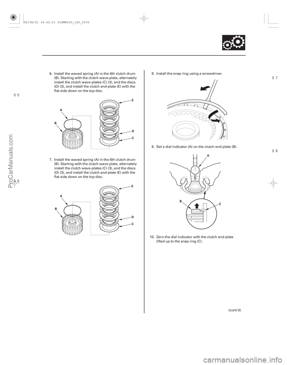
6. Install the waved spring (A) in the 4th clutch drum
(B). Starting with the clutch wave-plate, alternately
install the clutch wave-plates (C) (3), and the discs
(D) (3), and install the clutch end-plate (E) with the
flat side down on the top disc.
7. Install the waved spring (A) in the 5th clutch drum (B). Starting with the clutch wave-plate, alternately
install the clutch wave-plates (C) (3), and the discs
(D) (3), and install the clutch end-plate (E) with the
flat side down on the top disc. 8. Install the snap ring using a screwdriver.
9. Set a dial indicator (A) on the clutch end-plate (B).
10. Zero the dial indicator with the clutch end-plate lifteduptothesnapring(C).
(cont’d)
08/08/21 14:52:21 61SNR030_140_0335
ProCarManuals.com
DYNOMITE -2009-
Page 1258 of 2893

2nd Clutch: 0.75 0.95 mm (0.030 0.037")
�µ�µ �µ
����
�
��
�µ�µ
�µ�µ
�µ�µ
�µ�µ
�µ�µ
Clearance between Clutch End-Plate and Top Disc
Service Limit:
1st Clutch: 1.23 1.43 mm (0.048 0.056 in.)
2nd Clutch: 0.75 0.95 mm (0.030 0.037 in.)
3rd Clutch: 0.83 1.03 mm (0.033 0.041 in.)
4th Clutch: 0.73 0.93 mm (0.029 0.037 in.)
5th Clutch: 0.73 0.93 mm (0.029 0.037 in.) 1ST and 3RD CLUTCH END-PLATES
Mark Part Number Thickness
2ND CLUTCH END-PLATES Mark Part Number Thickness
4TH and 5TH CLUTCH END-PLATES Mark Part Number Thickness
14-334Shafts and Clutches
Clutch Clearance Inspection (cont’d)
B
A
D
C07ZAE-PRP0100
11. Release the clutch end-plate to lower the clutch
end-plate, then put the clutch compressor
attachment on the end-plate (A).
12. Press the clutch compressor attachment down with 150 160 N (15 16 kgf, 33 35 lbf) using a force
gauge, and read the dial indicator (B).
13. The dial indicator reads the clearance (C) between the clutch end-plate and top disc (D). Take
measurements in at least three places, and use
average as the actual clearance.
14. If the clearance is out of the service limit, select a new clutch end-plate from the following table. 1 22551-PRP-003 2.3 mm (0.091 in.)
2 22552-PRP-003 2.4 mm (0.094 in.)
3 22553-PRP-003 2.5 mm (0.098 in.)
4 22554-PRP-003 2.6 mm (0.102 in.)
5 22555-PRP-003 2.7 mm (0.106 in.)
6 22556-PRP-003 2.8 mm (0.110 in.)
7 22557-PRP-003 2.9 mm (0.114 in.)
8 22558-PRP-003 3.0 mm (0.118 in.)
9 22559-PRP-003 3.1 mm (0.122 in.)
10 22560-PRP-003 3.2 mm (0.126 in.)
11 22561-PRP-003 3.3 mm (0.130 in.)
12 22562-PRP-003 3.4 mm (0.134 in.)
1 22571-PRP-003 2.6 mm (0.102 in.)
2 22572-PRP-003 2.7 mm (0.106 in.)
3 22573-PRP-003 2.8 mm (0.110 in.)
4 22574-PRP-003 2.9 mm (0.114 in.)
5 22575-PRP-003 3.0 mm (0.118 in.)
6 22576-PRP-003 3.1 mm (0.122 in.)
7 22577-PRP-003 3.2 mm (0.126 in.)
8 22578-PRP-003 3.3 mm (0.130 in.)
9 22579-PRP-003 3.4 mm (0.134 in.)
1 22581-R91-003 or 22581-R93-003 2.1 mm (0.083 in.)
2 22582-R91-003 or 22582-R93-003 2.2 mm (0.087 in.)
3 22583-R91-003 or 22583-R93-003 2.3 mm (0.091 in.)
4 22584-R91-003 or 22584-R93-003 2.4 mm (0.094 in.)
5 22585-R91-003 or 22585-R93-003 2.5 mm (0.098 in.)
6 22586-R91-003 or 22586-R93-003 2.6 mm (0.102 in.)
7 22587-R91-003 or 22587-R93-003 2.7 mm (0.106 in.)
8 22588-R91-003 or 22588-R93-003 2.8 mm (0.110 in.)
9 22589-R91-003 or 22589-R93-003 2.9 mm (0.114 in.)
15. Install a new clutch end-plate, then recheck the clearance.
16. If the thickest clutch end-plate is installed, but the clearance is still over the service limit, replace the
clutch discs and the plates.
08/08/21 14:52:22 61SNR030_140_0336
ProCarManuals.com
DYNOMITE -2009-
Page 1259 of 2893
���
����
����
�(�#�'�������
���
�����
�
���
�������
�!�����)����
Special Tools Required
14-335
1st, 2nd, and 3rd Clutch Reassembly
A
D
B
C A
B
A B
C
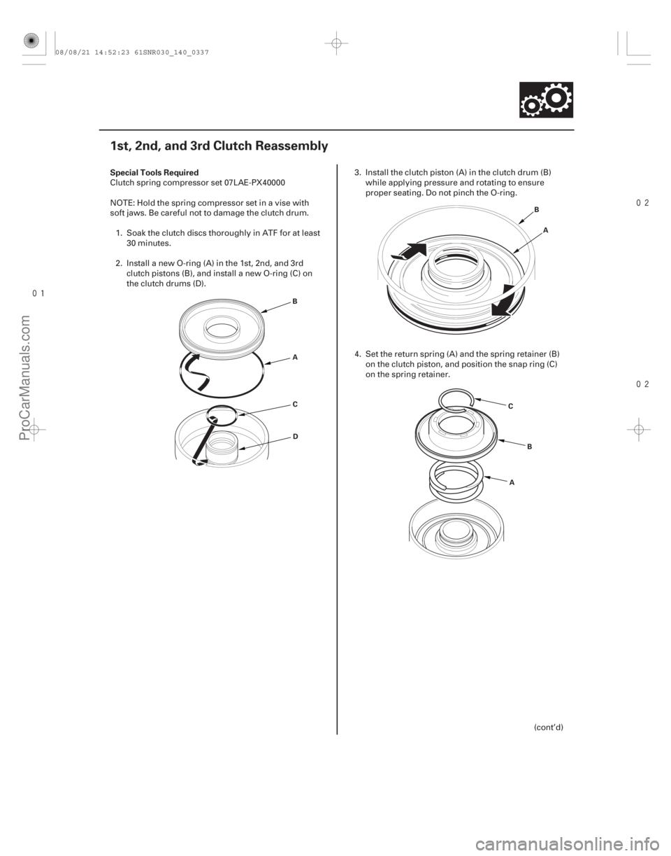
Clutch spring compressor set 07LAE-PX40000
NOTE: Hold the spring compressor set in a vise with
soft jaws. Be careful not to damage the clutch drum.
1. Soak the clutch discs thoroughly in ATF for at least 30 minutes.
2. Install a new O-ring (A) in the 1st, 2nd, and 3rd clutch pistons (B), and install a new O-ring (C) on
the clutch drums (D). 3. Install the clutch piston (A) in the clutch drum (B)
while applying pressure and rotating to ensure
proper seating. Do not pinch the O-ring.
4. Set the return spring (A) and the spring retainer (B) on the clutch piston, and position the snap ring (C)
on the spring retainer.
(cont’d)
08/08/21 14:52:23 61SNR030_140_0337
ProCarManuals.com
DYNOMITE -2009-