Page 1139 of 2893
 F
E
B
9. Remove the mounting bolts, the harness clampbrackets (A), and A/T clutch pressure control
solenoid valves B and C.
10. Rem")
���������
14-223
AD
BC
A
6x1.0mm
12 N·m (1.2 kgf·m, 8.7 lbf·ft) F
E
B
9. Remove the mounting bolts, the harness clampbrackets (A), and A/T clutch pressure control
solenoid valves B and C.
10. Remove the ATF joint pipes (D), the O-rings (E), and the gasket (F).
11. Check the fluid passage of the solenoid valves for contamination. 12. Connect a jumper wire from the negative battery
terminal to A/T clutch pressure control solenoid
valve B connector terminal No. 2, and connect
another jumper wire from the positive battery
terminal to connector terminal No. 1. Make sure
A/T clutch pressure control solenoid valve B moves.
13. Disconnect one of the jumper wires, and check valve movement at the fluid passage in the valve
body mounting surface. If the valve binds or moves
sluggishly, or if the solenoid valve does not operate,
replace A/T clutch pressure control solenoid valves
BandC.
14. Clean the mounting surfaces and the fluid passages of the A/T clutch pressure control solenoid valve
body and the transmission housing.
15. Install a new gasket on the transmission housing.
NOTE: Be sure to install a new gasket with the blue
side toward the transmission housing.
16. Install the ATF joint pipes, and install new O-rings over the ATF joint pipes.
17. Install A/T clutch pressure control solenoid valves B and C.
18. Check the connectors for rust, dirt, or oil, clean or repair if necessary, then connect the connectors
securely.
19. Install the air cleaner assembly (see page 11-345) and the intake air duct (see page 11-348).
Replace.
Replace.
08/08/21 14:46:48 61SNR030_140_0225
ProCarManuals.com
DYNOMITE -2009-
Page 1140 of 2893
���
�µ
Standard: 3 10
14-224
Automatic Transmission
A/T Clutch Pressure Control Solenoid Valve C Test
A
A
1. Connect the HDS to the DLC (A) loc")
��������
�(�#�'�������
���
�����
�����
���������������)���
�µ
Standard: 3 10
14-224
Automatic Transmission
A/T Clutch Pressure Control Solenoid Valve C Test
A
A
1. Connect the HDS to the DLC (A) located under the
driver’s side of the dashboard.
2. Turn the ignition switch to ON (II). Make sure the HDS communicates with the PCM. If it does not, go
to the DLC circuit troubleshooting (see page
11-204).
3. Select Clutch Pressure Control (Linear) Solenoid Valve C in the Miscellaneous Test Menu with the
HDS.
4. Test A/T clutch pressure control solenoid valve C with the HDS.
If the valve tests OK, the test is complete. Disconnect the HDS.
If the valve does not test OK, follow the instructions on the HDS.
If the valve does not test OK, and the HDS does not determine the cause, go to step 5.
5. Remove the intake air duct (see page 11-348) and the air cleaner assembly (see page 11-345). 6. Disconnect the A/T clutch pressure control solenoid
valve C connector (A).
7. Measure the resistance between A/T clutch pressure control solenoid valve C connector
terminals No. 1 and No. 2.
If the resistance is within the standard, go to step 8.
If the resistance is out of standard, replace A/T clutch pressure control solenoid valve C
(see page 14-226).
8. Connect a jumper wire from the negative battery terminal to solenoid valve C connector terminal
No. 2, and connect another jumper wire from the
positive battery terminal to connector terminal
No. 1.
If a clicking sound is heard, the valve is OK, and the test is complete, go to step 18.
If no clicking sound is heard, go to step 9.
08/08/21 14:46:48 61SNR030_140_0226
ProCarManuals.com
DYNOMITE -2009-
Page 1141 of 2893
 F
E
C
9. Remove the mounting bolts, the harness clampbrackets (A), and A/T clutch pressure control
solenoid valves B and C.
10. Rem")
���������
14-225
AD
BC
A
6x1.0mm
12 N·m (1.2 kgf·m, 8.7 lbf·ft) F
E
C
9. Remove the mounting bolts, the harness clampbrackets (A), and A/T clutch pressure control
solenoid valves B and C.
10. Remove the ATF joint pipes (D), the O-rings (E), and the gasket (F).
11. Check the fluid passage of the solenoid valves for contamination. 12. Connect a jumper wire from the negative battery
terminal to A/T clutch pressure control solenoid
valve C connector terminal No. 2, and connect
another jumper wire from the positive battery
terminal to connector terminal No. 1. Make sure
A/T clutch pressure control solenoid valve C moves.
13. Disconnect one of the jumper wires, and check valve movement at the fluid passage in the valve
body mounting surface. If the valve binds or moves
sluggishly, or if the solenoid valve does not operate,
replace A/T clutch pressure control solenoid valves
BandC.
14. Clean the mounting surfaces and the fluid passages of the A/T clutch pressure control solenoid valve
body and the transmission housing.
15. Install a new gasket on the transmission housing.
NOTE: Be sure to install a new gasket with the blue
side toward the transmission housing.
16. Install the ATF joint pipes, and install new O-rings over the ATF joint pipes.
17. Install A/T clutch pressure control solenoid valves B and C.
18. Check the connectors for rust, dirt, or oil, clean or repair if necessary, then connect the connectors
securely.
19. Install the air cleaner assembly (see page 11-345) and the intake air duct (see page 11-348).
Replace.
Replace.
08/08/21 14:46:49 61SNR030_140_0227
ProCarManuals.com
DYNOMITE -2009-
Page 1142 of 2893
�
��
14-226Automatic Transmission
A/T Clutch Pressure Control Solenoid Valve B and C Replacement
A
D
BC
A
6x1.0mm
12 N·m (1.2 kgf·m, 8.7 lbf·ft)")
������(�#�'�������
���
�����
�����
��������� �����)�
��
14-226Automatic Transmission
A/T Clutch Pressure Control Solenoid Valve B and C Replacement
A
D
BC
A
6x1.0mm
12 N·m (1.2 kgf·m, 8.7 lbf·ft) F
E
1. Remove the intake air duct (see page 11-348) and the air cleaner assembly (see page 11-345).
2. Disconnect the A/T clutch pressure control solenoid valves B and C connectors.
3. Remove the mounting bolts, the harness clamp brackets (A), and A/T clutch pressure control
solenoid valves B and C.
4. Remove the ATF joint pipes (D), the O-rings (E), and the gasket (F). 5. Clean the mounting surface and the fluid passage
of the transmission housing.
6. Install a new gasket on the transmission housing, and install the ATF joint pipes.
NOTE: Be sure to install a new gasket with the blue
side toward the transmission housing.
7. Install new O-rings over the ATF joint pipes.
8. Install new A/T clutch pressure control solenoid valves B and C, and harness clamp brackets.
9. Check the connectors for rust, dirt, or oil, clean or repair if necessary, then connect it securely.
10. Install the air cleaner assembly (see page 11-345) and the intake air duct (see page 11-348).
Replace.
Replace.
08/08/21 14:46:49 61SNR030_140_0228
ProCarManuals.com
DYNOMITE -2009-
Page 1144 of 2893
���� ����
�(�#��������
���
�����
�����
���
�
�
� �����)����
14-22814-228 Automatic Transmission
2nd Clutch Transmission Fluid
Pressure Sw")
���
����
�(�#�'�������
���
�����
�����
���
���
� �����)���� ����
�(�#�'�������
���
�����
�����
���
�
�
� �����)����
14-22814-228 Automatic Transmission
2nd Clutch Transmission Fluid
Pressure Switch Replacement
3rd Clutch Transmission Fluid
Pressure Switch Replacement
A
B
A
20 N·m (2.0 kgf·m, 14 lbf·ft) B
B
20 N·m
(2.0 kgf·m, 14 lbf·ft)
A C
1. Remove the intake air duct (see page 11-348) and
the air cleaner assembly (see page 11-345).
2. Remove the harness cover (A) from its bracket (B).
3. Disconnect the 2nd clutch transmission fluid pressure switch connector, and remove the 2nd
clutch transmission fluid pressure switch (A).
4. Install a new 2nd clutch transmission fluid pressure switch with a new sealing washer (B), and tighten
the metal part of the switch, not the plastic part.
5. Check the connector for rust, dirt, or oil, clean or repair if necessary, then connect the connector
securely.
6. Install the harness cover on its bracket.
7. Install the air cleaner assembly (see page 11-345) and the intake air duct (see page 11-348). 1. Do the battery removal procedure (see page 22-69).
2. Remove the intake air duct (see page 11-348) and
the air cleaner assembly (see page 11-345).
3. Remove the battery tray, the battery base, and the resonator.
4. Disconnect the 3rd clutch transmission fluid pressure switch connector (A), then remove the 3rd
clutch transmission fluid pressure switch (B) with
the sealing washer (C).
5. Install a new 3rd clutch transmission fluid pressure switch with a new sealing washer, and tighten the
metal part of the switch, not the plastic part.
6. Check the connector for rust, dirt, or oil, clean or repair if necessary, then connect the connector
securely.
7. Install the battery tray, the battery base, and the resonator.
8. Install the air cleaner assembly (see page 11-345) and the intake air duct (see page 11-348).
9. Do the battery installation procedure (see page 22-69).
Replace.
Replace.
08/08/21 14:46:50 61SNR030_140_0230
ProCarManuals.com
DYNOMITE -2009-
Page 1150 of 2893

A
B
C
DD
A
B C
D
E
F
C
GA B
C
D E
D E
12. Disconnect the A/T clutch pressure control solenoid
valve A connector (A) and")
����
��������
����
14-234Automatic Transmission
Transmission Removal (cont’d)
A
B
C
DD
A
B C
D
E
F
C
GA B
C
D E
D E
12. Disconnect the A/T clutch pressure control solenoid
valve A connector (A) and the 2nd clutch
transmission fluid pressure switch connector (B),
and remove the harness clamps (C) from the clamp
brackets (D).
13. Remove the harness clamp (A) from the clamp bracket (B). Disconnect the transmission range
switch connector (C), and remove the connector
from its bracket.
14. Disconnect the output shaft (countershaft) speed sensor connector (D) and the input shaft
(mainshaft) speed sensor connector (E), and
remove the harness clamp (F) from the clamp
bracket (G). 15. Disconnect the 3rd clutch transmission fluid
pressure switch connector.
16. Disconnect the shift solenoid wire harness connector (A), the A/T clutch pressure control
solenoid valve B connector (B), and the A/T clutch
pressure control solenoid valve C connector (C),
then remove the harness clamps (D) from the
clamp brackets (E).
08/08/21 14:46:54 61SNR030_140_0236
ProCarManuals.com
DYNOMITE -2009-
Page 1165 of 2893
����
��������
����
14-249
A
B
AB
C
C
A
B
6x1.0mm
12 N·m (1.2 kgf·m, 8.7 lbf·ft) A
B C
A B
C
D E
D E
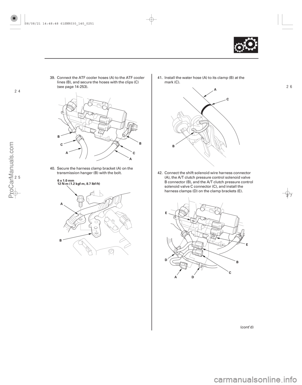
39. Connect the ATF cooler hoses (A) to the ATF cooler
lines (B), and secure the hoses with the clips (C)
(see page 14-253).
40. Secure the harness clamp bracket (A) on the transmission hanger (B) with the bolt. 41. Install the water hose (A) to its clamp (B) at the
mark (C).
42. Connect the shift solenoid wire harness connector (A), the A/T clutch pressure control solenoid valve
B connector (B), and the A/T clutch pressure control
solenoid valve C connector (C), and install the
harness clamps (D) on the clamp brackets (E).
(cont’d)
08/08/21 14:48:48 61SNR030_140_0251
ProCarManuals.com
DYNOMITE -2009-
Page 1166 of 2893
����
���
����
����
14-250Automatic Transmission
Transmission Installation (cont’d)
E
F
A
B
C
D
G A
B
C
DD
A
B
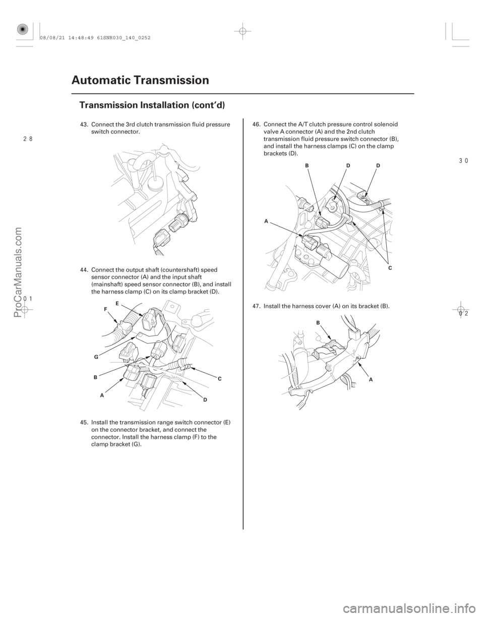
43. Connect the 3rd clutch transmission fluid pressure
switch connector.
44. Connect the output shaft (countershaft) speed sensor connector (A) and the input shaft
(mainshaft) speed sensor connector (B), and install
the harness clamp (C) on its clamp bracket (D).
45. Install the transmission range switch connector (E) on the connector bracket, and connect the
connector. Install the harness clamp (F) to the
clamp bracket (G). 46. Connect the A/T clutch pressure control solenoid
valve A connector (A) and the 2nd clutch
transmission fluid pressure switch connector (B),
and install the harness clamps (C) on the clamp
brackets (D).
47. Install the harness cover (A) on its bracket (B).
08/08/21 14:48:49 61SNR030_140_0252
ProCarManuals.com
DYNOMITE -2009-