Page 1242 of 2893
���
����
�(�#�'�������
���
�����
�
������������� �����)�
��
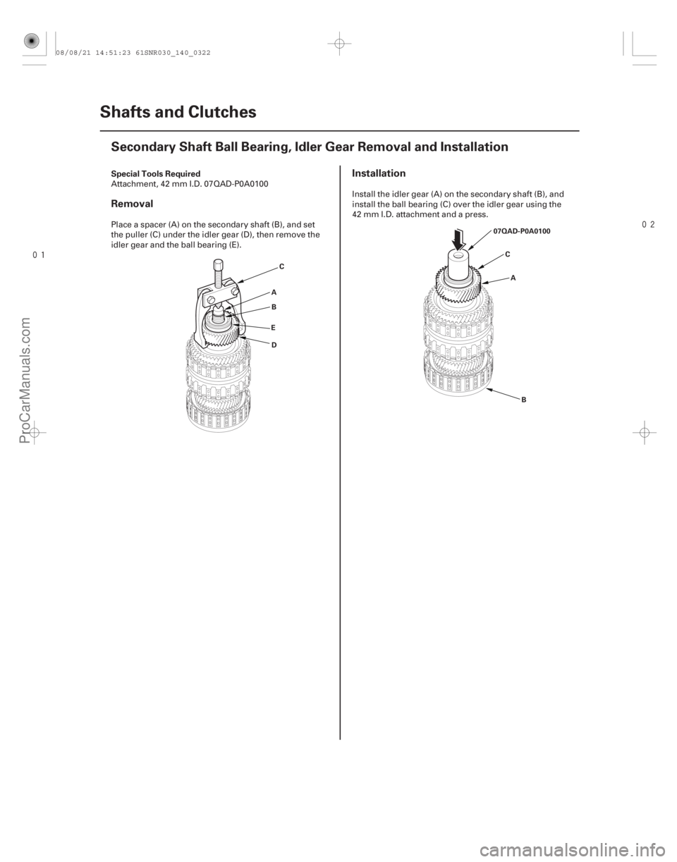
Special Tools Required
Removal
Installation
14-320Shafts and Clutches
Secondary Shaft Ball Bearing, Idler Gear Removal and Installation
C
A B
E D
B
C
A
07QAD-P0A0100
Attachment, 42 mm I.D. 07QAD-P0A0100
Place a spacer (A) on the secondary shaft (B), and set
the puller (C) under the idler gear (D), then remove the
idler gear and the ball bearing (E).
Install the idler gear (A) on the secondary shaft (B), and
install the ball bearing (C) over the idler gear using the
42 mm I.D. attachment and a press.
08/08/21 14:51:23 61SNR030_140_0322
ProCarManuals.com
DYNOMITE -2009-
Page 1243 of 2893
���
����
����
�(�#�'�������
���
�����
�
�������
���
�"�����)���� �µ�µ
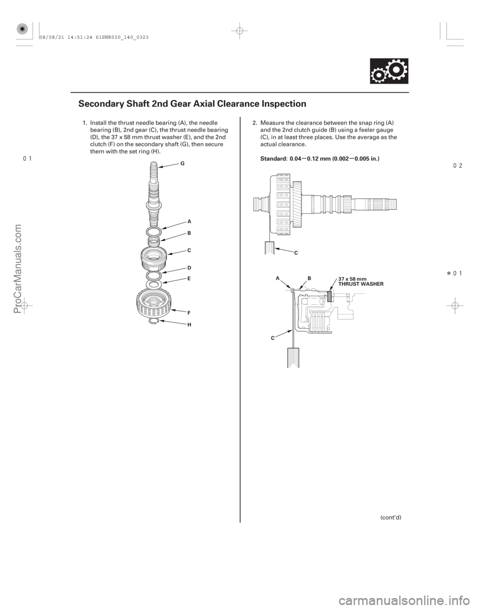
Standard: 0.04 0.12 mm (0.002 0.005 in.)
14-321
Secondary Shaft 2nd Gear Axial Clearance Inspection
G
AB
C
D
E
F H C
A B
C 37x58mm
THRUST WASHER
1. Install the thrust needle bearing (A), the needle
bearing (B), 2nd gear (C), the thrust needle bearing
(D), the 37 x 58 mm thrust washer (E), and the 2nd
clutch (F) on the secondary shaft (G), then secure
them with the set ring (H). 2. Measure the clearance between the snap ring (A)
and the 2nd clutch guide (B) using a feeler gauge
(C), in at least three places. Use the average as the
actual clearance.
(cont’d)
08/08/21 14:51:24 61SNR030_140_0323
ProCarManuals.com
DYNOMITE -2009-
Page 1244 of 2893
����
THRUST WASHER, 37 x 58 mm
No. Part Number Thickness Special Tools Required
14-32214-322Shafts and Clutches
Secondary Shaft 2nd Gear Axial
Cleara")
���
�(�#�'�������
���
�����
�
�������
���
�"�����)����
THRUST WASHER, 37 x 58 mm
No. Part Number Thickness Special Tools Required
14-32214-322Shafts and Clutches
Secondary Shaft 2nd Gear Axial
Clearance Inspection (cont’d)
Secondary Shaft 1st Gear Axial
Clearance Inspection
L
24x1.25mm
29N·m(3.0kgf·m,22lbf·ft)
K
J I
G
F
E
D
C
B A
H
3. If the clearance is out of standard, remove the 37 x 58 mm thrust washer and measure its
thickness.
4. Select and install a new thrust washer, then recheck.
1 90511-PRP-010 3.900 mm (0.154 in.)
2 90512-PRP-010 3.925 mm (0.155 in.)
3 90513-PRP-010 3.950 mm (0.156 in.)
4 90514-PRP-010 3.975 mm (0.156 in.)
5 90515-PRP-010 4.000 mm (0.157 in.)
6 90516-PRP-010 4.025 mm (0.158 in.)
7 90517-PRP-010 4.050 mm (0.159 in.)
8 90518-PRP-010 4.075 mm (0.160 in.)
9 90519-PRP-010 4.100 mm (0.161 in.)
10 90520-PRP-010 4.125 mm (0.162 in.)
11 90521-PRP-010 4.150 mm (0.163 in.)
12 90522-PRP-010 4.175 mm (0.164 in.)
13 90523-PRP-000 4.200 mm (0.165 in.)
14 90524-PRP-000 4.225 mm (0.166 in.)
15 90525-PRP-000 4.250 mm (0.167 in.)
16 90526-PRP-000 4.275 mm (0.168 in.)
17 90527-PRP-000 4.300 mm (0.169 in.)
18 90528-PRP-000 4.325 mm (0.170 in.)
19 90529-PRP-000 4.350 mm (0.171 in.)
20 90530-PRP-000 4.375 mm (0.172 in.)
5. After replacing the thrust washer, make sure the clearance is within standard.
6. Disassemble the installed parts from the secondary shaft. Attachment, 42 mm I.D. 07QAD-P0A0100
1. Install the thrust needle bearing (A), the needle bearing (B), 1st gear (C), the thrust needle bearing
(D), the 40 x 51.5 mm thrust washer (E), the 1st/3rd
clutch (F), and the 3rd gear collar (G) on the
secondary shaft (H). Do not install the O-rings
during inspection.
08/08/21 14:51:24 61SNR030_140_0324
ProCarManuals.com
DYNOMITE -2009-
Page 1245 of 2893
����
THRUST WASHER, 37 x 58 mm
No. Part Number Thickness Special Tools Required
14-32214-322Shafts and Clutches
Secondary Shaft 2nd Gear Axial
Cleara")
���
�(�#�'�������
���
�����
�
�������
���
�"�����)����
THRUST WASHER, 37 x 58 mm
No. Part Number Thickness Special Tools Required
14-32214-322Shafts and Clutches
Secondary Shaft 2nd Gear Axial
Clearance Inspection (cont’d)
Secondary Shaft 1st Gear Axial
Clearance Inspection
L
24x1.25mm
29N·m(3.0kgf·m,22lbf·ft)
K
J I
G
F
E
D
C
B A
H
3. If the clearance is out of standard, remove the 37 x 58 mm thrust washer and measure its
thickness.
4. Select and install a new thrust washer, then recheck.
1 90511-PRP-010 3.900 mm (0.154 in.)
2 90512-PRP-010 3.925 mm (0.155 in.)
3 90513-PRP-010 3.950 mm (0.156 in.)
4 90514-PRP-010 3.975 mm (0.156 in.)
5 90515-PRP-010 4.000 mm (0.157 in.)
6 90516-PRP-010 4.025 mm (0.158 in.)
7 90517-PRP-010 4.050 mm (0.159 in.)
8 90518-PRP-010 4.075 mm (0.160 in.)
9 90519-PRP-010 4.100 mm (0.161 in.)
10 90520-PRP-010 4.125 mm (0.162 in.)
11 90521-PRP-010 4.150 mm (0.163 in.)
12 90522-PRP-010 4.175 mm (0.164 in.)
13 90523-PRP-000 4.200 mm (0.165 in.)
14 90524-PRP-000 4.225 mm (0.166 in.)
15 90525-PRP-000 4.250 mm (0.167 in.)
16 90526-PRP-000 4.275 mm (0.168 in.)
17 90527-PRP-000 4.300 mm (0.169 in.)
18 90528-PRP-000 4.325 mm (0.170 in.)
19 90529-PRP-000 4.350 mm (0.171 in.)
20 90530-PRP-000 4.375 mm (0.172 in.)
5. After replacing the thrust washer, make sure the clearance is within standard.
6. Disassemble the installed parts from the secondary shaft. Attachment, 42 mm I.D. 07QAD-P0A0100
1. Install the thrust needle bearing (A), the needle bearing (B), 1st gear (C), the thrust needle bearing
(D), the 40 x 51.5 mm thrust washer (E), the 1st/3rd
clutch (F), and the 3rd gear collar (G) on the
secondary shaft (H). Do not install the O-rings
during inspection.
08/08/21 14:51:24 61SNR030_140_0324
ProCarManuals.com
DYNOMITE -2009-
Page 1247 of 2893
����
THRUST WASHER, 40 x 51.5 mm (’06 Model)
No. Part Number Thickness
THRUST WASHER, 40 x 51.5 mm (’07-09 Models) No. Part Number Thickness
14-3")
���
�(�#�'�������
���
�����
�������������
� �����)����
THRUST WASHER, 40 x 51.5 mm (’06 Model)
No. Part Number Thickness
THRUST WASHER, 40 x 51.5 mm (’07-09 Models) No. Part Number Thickness
14-32414-324Shafts and Clutches
Secondary Shaft 1st Gear Axial
Clearance Inspection (cont’d)
Idler Gear Shaft Removal and
Installation
D
C
B A
7. If the clearance is out of standard, remove the 40 x 51.5 mm thrust washer and measure its
thickness.
8. Select and install a new thrust washer, then recheck.
1 90503-PRP-000 4.80 mm (0.189 in.)
2 90504-PRP-000 4.85 mm (0.191 in.)
3 90505-PRP-000 4.90 mm (0.193 in.)
4 90506-PRP-000 4.95 mm (0.195 in.)
5 90507-PRP-000 5.00 mm (0.197 in.)
6 90508-PRP-000 5.05 mm (0.199 in.)
1 90503-RCT-000 4.80 mm (0.189 in.)
2 90504-RCT-000 4.85 mm (0.191 in.)
3 90505-RCT-000 4.90 mm (0.193 in.)
4 90506-RCT-000 4.95 mm (0.195 in.)
5 90507-RCT-000 5.00 mm (0.197 in.)
6 90508-RCT-000 5.05 mm (0.199 in.)
9. After replacing the thrust washer, make sure the clearance is within standard.
10. Disassemble the installed parts from the secondary shaft. 1. Remove the snap ring (A), the cotter retainer (B),
and the cotters (C). Do not distort the snap ring.
2. Remove the idler gear shaft/idler gear assembly (D) from the transmission housing.
3. Check the snap ring and the cotter retainer for wear and damage. Replace them if they are worn,
distorted, or damaged.
4. Install the idler gear and the idler gear shaft in the reverse order of removal.
08/08/21 14:51:25 61SNR030_140_0326
ProCarManuals.com
DYNOMITE -2009-
Page 1248 of 2893
����
THRUST WASHER, 40 x 51.5 mm (’06 Model)
No. Part Number Thickness
THRUST WASHER, 40 x 51.5 mm (’07-09 Models) No. Part Number Thickness
14-3")
���
�(�#�'�������
���
�����
�������������
� �����)����
THRUST WASHER, 40 x 51.5 mm (’06 Model)
No. Part Number Thickness
THRUST WASHER, 40 x 51.5 mm (’07-09 Models) No. Part Number Thickness
14-32414-324Shafts and Clutches
Secondary Shaft 1st Gear Axial
Clearance Inspection (cont’d)
Idler Gear Shaft Removal and
Installation
D
C
B A
7. If the clearance is out of standard, remove the 40 x 51.5 mm thrust washer and measure its
thickness.
8. Select and install a new thrust washer, then recheck.
1 90503-PRP-000 4.80 mm (0.189 in.)
2 90504-PRP-000 4.85 mm (0.191 in.)
3 90505-PRP-000 4.90 mm (0.193 in.)
4 90506-PRP-000 4.95 mm (0.195 in.)
5 90507-PRP-000 5.00 mm (0.197 in.)
6 90508-PRP-000 5.05 mm (0.199 in.)
1 90503-RCT-000 4.80 mm (0.189 in.)
2 90504-RCT-000 4.85 mm (0.191 in.)
3 90505-RCT-000 4.90 mm (0.193 in.)
4 90506-RCT-000 4.95 mm (0.195 in.)
5 90507-RCT-000 5.00 mm (0.197 in.)
6 90508-RCT-000 5.05 mm (0.199 in.)
9. After replacing the thrust washer, make sure the clearance is within standard.
10. Disassemble the installed parts from the secondary shaft. 1. Remove the snap ring (A), the cotter retainer (B),
and the cotters (C). Do not distort the snap ring.
2. Remove the idler gear shaft/idler gear assembly (D) from the transmission housing.
3. Check the snap ring and the cotter retainer for wear and damage. Replace them if they are worn,
distorted, or damaged.
4. Install the idler gear and the idler gear shaft in the reverse order of removal.
08/08/21 14:51:25 61SNR030_140_0326
ProCarManuals.com
DYNOMITE -2009-
Page 1250 of 2893
���
��������
����
�(�#�'�������
���
�����
�
���
�������
�!�����)����
Special Tools Required
14-326
Shafts and Clutches
Clutch Disassembly
B
A
C
E D B
A
C
F E
D
B A
C
D
F
E
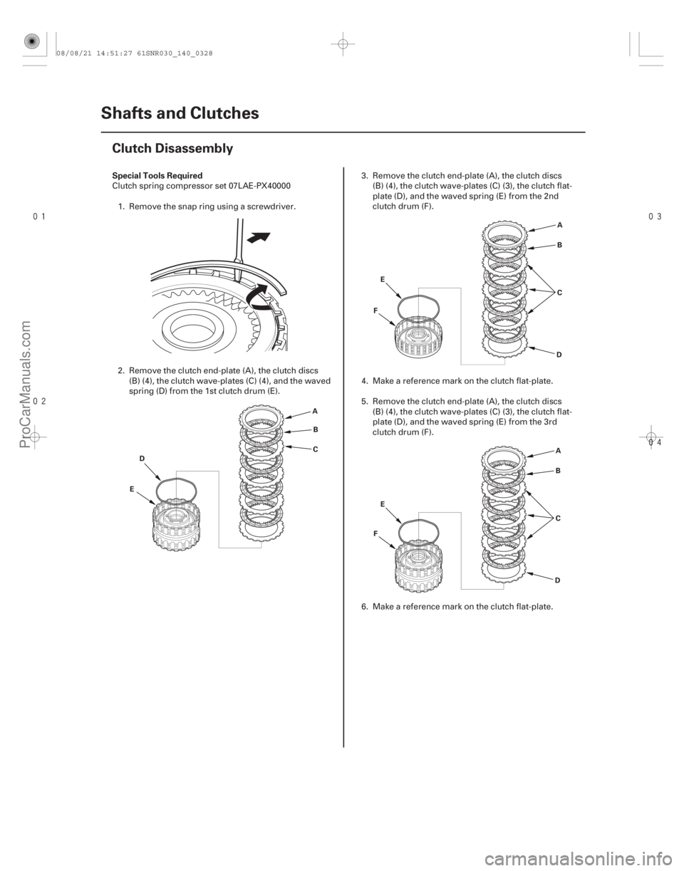
Clutch spring compressor set 07LAE-PX40000
1. Remove the snap ring using a screwdriver.
2. Remove the clutch end-plate (A), the clutch discs (B) (4), the clutch wave-plates (C) (4), and the waved
spring (D) from the 1st clutch drum (E). 3. Remove the clutch end-plate (A), the clutch discs
(B) (4), the clutch wave-plates (C) (3), the clutch flat-
plate (D), and the waved spring (E) from the 2nd
clutch drum (F).
4. Make a reference mark on the clutch flat-plate.
5. Remove the clutch end-plate (A), the clutch discs (B) (4), the clutch wave-plates (C) (3), the clutch flat-
plate (D), and the waved spring (E) from the 3rd
clutch drum (F).
6. Make a reference mark on the clutch flat-plate.
08/08/21 14:51:27 61SNR030_140_0328
ProCarManuals.com
DYNOMITE -2009-
Page 1251 of 2893
���
��������
����
14-327
E A
B C
D
AB
E C
D 07LAE-PX40000
A
B
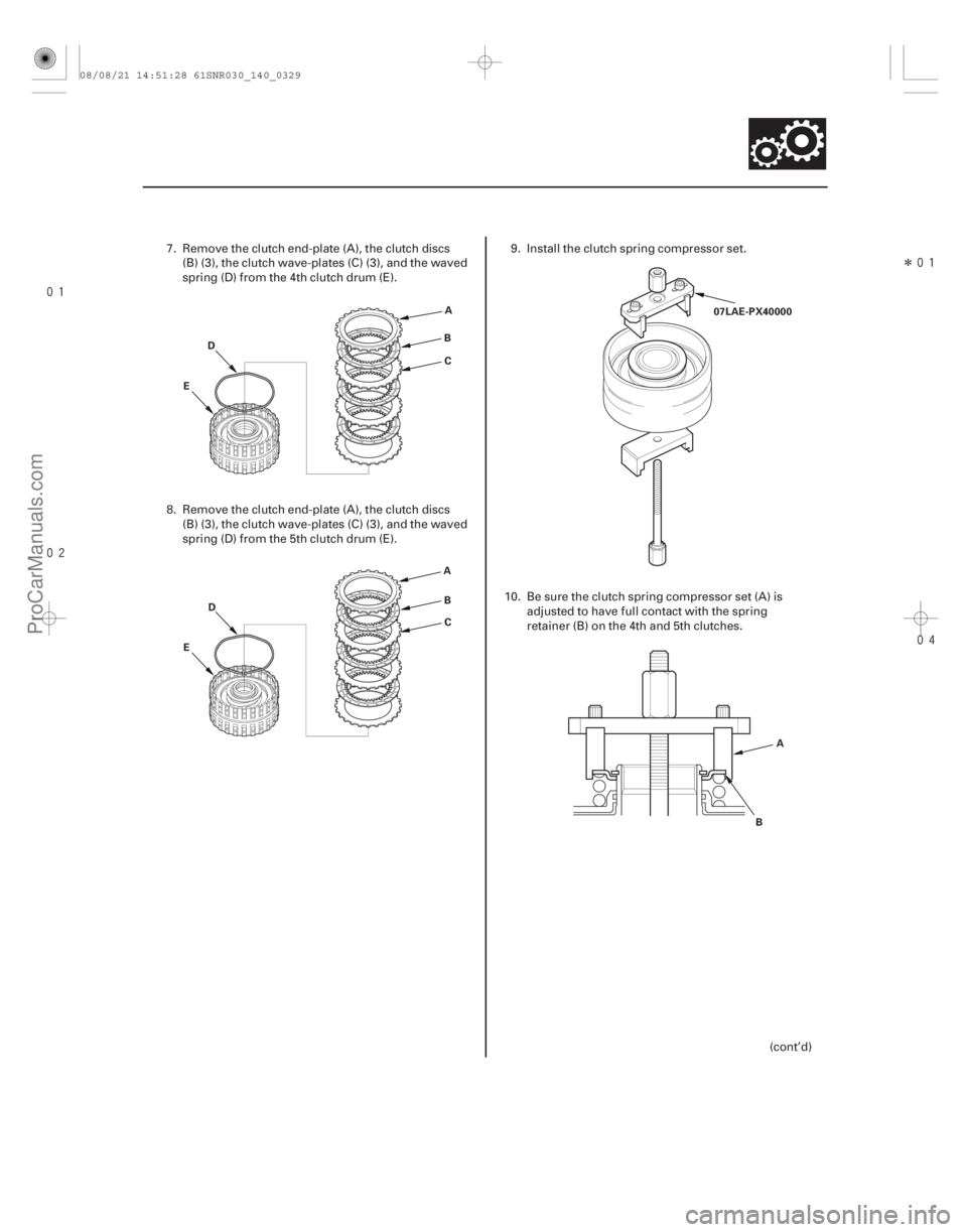
7. Remove the clutch end-plate (A), the clutch discs (B) (3), the clutch wave-plates (C) (3), and the waved
spring (D) from the 4th clutch drum (E).
8. Remove the clutch end-plate (A), the clutch discs (B) (3), the clutch wave-plates (C) (3), and the waved
spring (D) from the 5th clutch drum (E). 9. Install the clutch spring compressor set.
10. Be sure the clutch spring compressor set (A) is adjusted to have full contact with the spring
retainer (B) on the 4th and 5th clutches.
(cont’d)
08/08/21 14:51:28 61SNR030_140_0329
ProCarManuals.com
DYNOMITE -2009-