Page 2217 of 2893
����
�µ
�µ�µ �µ
�µ
�µ
DTC B1175:
YES
NO YES NO
YES
NO
22-267
FUEL TANK UNIT 4P CONNECTOR
GND (LT GRN)
JUMPER WIRE
FUEL UNIT
(ORN)
JUMPER")
���
����
�(�#�'��������� �������������.�
�
�����������)����
�µ
�µ�µ �µ
�µ
�µ
DTC B1175:
YES
NO YES NO
YES
NO
22-267
FUEL TANK UNIT 4P CONNECTOR
GND (LT GRN)
JUMPER WIRE
FUEL UNIT
(ORN)
JUMPER WIRE GAUGE CONTROL MODULE (TACH) 36P CONNECTOR
FUEL UNIT (PUR) GND (ORN)
Fuel Level Sensor (Fuel Gauge
Sending Unit) Circuit Open
NOTE: If you are troubleshooting multiple DTCs, be
sure to follow the instructions in B-CAN System
Diagnosis Test Mode A (see page 22-93).
1. Clear the DTCs with the HDS.
2. Turn the ignition switch to LOCK (0), and then back to ON (II).
3. Wait for 30 seconds.
4. Check for DTCs with the HDS.
Go to step 5.
Intermittent failure, the fuel level sensor
circuit is OK at this time. Check for loose or poor
connections.
5. Turn the ignition switch to LOCK (0).
6. Disconnect the fuel tank unit 5P connector and the gauge control module (tach) 36P connector.
7. Connect fuel tank unit 4P connector terminals No. 1 and No. 3 to body ground with jumper wires. 8. Check for continuity between gauge control
module (tach) 36P connector terminals No. 32 and
No. 33 and body ground individually.
Go to step 9.
Repair an open in the wire between the gauge
control module (tach) and the fuel tank unit.
9. Do the fuel gauge sending unit test (see page 11-340).
Replace the gauge control module (tach)
(see page 22-277).
Replace the fuel tank unit (see page 11-339).
Wire side of female terminals Wire side of female terminals
I s DT C B117 5 i nd i cat ed ?
Is there continuity?
I s t he f uel gauge send i ng uni t OK ?
08/08/21 14:35:20 61SNR030_220_0269
ProCarManuals.com
DYNOMITE -2009-
Page 2218 of 2893
����
�µ
�µ
�µ
�µ �µ
�µ
DTC B1176:
YES
NO
YES
NO YES
NO
22-268Gauges
DTC Troubleshooting (cont’d)
GAUGE CONTROL MODULE (TACH) 36P CONNECTOR")
����
�(�#�'��������� �������������.�
�
�����������)����
�µ
�µ
�µ
�µ �µ
�µ
DTC B1176:
YES
NO
YES
NO YES
NO
22-268Gauges
DTC Troubleshooting (cont’d)
GAUGE CONTROL MODULE (TACH) 36P CONNECTOR
FUEL UNIT (PUR)
Fuel Level Sensor (Fuel Gauge
Sending Unit) Circuit Short
NOTE: If you are troubleshooting multiple DTCs, be
sure to follow the instructions in B-CAN System
Diagnosis Test Mode A (see page 22-93).
1. Clear the DTCs with the HDS.
2. Turn the ignition switch to LOCK (0), and then back to ON (II).
3. Wait for 30 seconds.
4. Check for DTCs with the HDS.
Go to step 5.
Intermittent failure, the fuel level sensor
circuit is OK at this time. Check for loose or poor
connections.
5. Turn the ignition switch to LOCK (0).
6. Disconnect the fuel tank unit 4P connector.
7. Clear the DTCs with the HDS.
8. Turn the ignition switch to LOCK (0), and then back to ON (II).
9. Wait for 30 seconds.
10. Check for DTCs with the HDS.
Go to step 11.
Replace the fuel gauge sending unit (see page
11-340). 11. Disconnect the gauge control module (tach) 36P
connector.
12. Check for continuity between gauge control module (tach) 36P connector terminal No. 32 and
body ground.
Repair a short in the wire between the gauge
control module (tach) and the fuel tank unit.
Replace the gauge control module (tach)
(see page 22-277).
Wire side of female terminals
I s DT C B117 6 i nd i cat ed ?
I s DT C B117 6 i nd i cat ed ? Is there continuity?
08/08/21 14:35:20 61SNR030_220_0270
ProCarManuals.com
DYNOMITE -2009-
Page 2219 of 2893
����
�µ
�µ
�µ
�µ �µ
�µ
�µ
�µ
DTC B1177:
YES
NO
YES
NO YES
NO
YES
NO
22-269
Battery Voltage Abnormal (’06
model)
NOTE: If you are troubleshooting")
�(�#�'��������� �������������.�
�
�����������)����
�µ
�µ
�µ
�µ �µ
�µ
�µ
�µ
DTC B1177:
YES
NO
YES
NO YES
NO
YES
NO
22-269
Battery Voltage Abnormal (’06
model)
NOTE: If you are troubleshooting multiple DTCs, be
sure to follow the instructions in B-CAN System
Diagnosis Test Mode A (see page 22-93).
1. Clear the DTCs with the HDS.
2. Turn the ignition switch to LOCK (0), and then back to ON (II).
3. Check for DTCs with the HDS.
Go to step 8.
Go to step 4.
4. Clear the DTCs with the HDS.
5. Turn the ignition switch to LOCK (0), and then back to ON (II).
6. Crank the engine.
7. Check for DTCs with the HDS.
Go to step 8.
Intermittent failure. The gauge control
module (tach) and power supply voltage (IG1) that
is supplied to the gauge control module (tach) are
OK at this time. The battery may have been
discharged, and recovered. 8. Check the battery (see page 22-67) and the
charging system.
Go to step 9.
The battery needs a recharge or replacement,
or the charging system needs to repaired.
9. Turn the ignition switch to ON (II).
10. With the gauge control module (tach) 36P connector still connected, measure the voltage
between gauge control module (tach) 36P
connector terminal No. 17 and body ground.
Replace the gauge control module (tach)
(see page 22-277).
Repair an open or high resistance in the BRN
wire between the ignition switch and the gauge
control module (tach).
I s DT C B117 7 i nd i cat ed ?
I s DT C B117 7 i nd i cat ed ? I s t he bat t er y cond i t i on nor mal and t he char gi ng
sy st em OK ?
I s t he v ol t age about 7 .5 V ?
08/08/21 14:35:58 61SNR030_220_0271
ProCarManuals.com
DYNOMITE -2009-
Page 2220 of 2893
����
�µ
�µ
�µ
�µ
�µ
�µ �µ
�µ
DTC B1183:
YES
NO
YES
NO
YES
NO YES
NO
22-270Gauges
DTC Troubleshooting (cont’d)
CAN L (RED)
CAN H (WHT)
EP")
����
�(�#�'��������� �������������.�
�
�����������)����
�µ
�µ
�µ
�µ
�µ
�µ �µ
�µ
DTC B1183:
YES
NO
YES
NO
YES
NO YES
NO
22-270Gauges
DTC Troubleshooting (cont’d)
CAN L (RED)
CAN H (WHT)
EPS CONTROL UNIT 28P CONNECTORCAN H (WHT)
CAN L (RED)
GAUGE CONTROL MODULE (TACH) 36P CONNECTOR
Gauge Control Module Lost
Communication with the EPS Control Unit
(EPS Message)
NOTE: If you are troubleshooting multiple DTCs, be
sure to follow the instructions in B-CAN System
Diagnosis Test Mode A (see page 22-93).
1. Clear the DTCs with the HDS.
2. Turn the ignition switch to LOCK (0), and then back to ON (II).
3. Wait for 6 seconds or more.
4. Check for DTCs with the HDS.
Go to step 5.
Intermittent failure. The gauge control
module (tach) is OK at this time. Check for loose or
poor connections.
5. Check for DTCs with the HDS.
Troubleshoot DTC B 1178.
Go to step 6.
6. Check for EPS DTCs with the HDS.
Troubleshoot the indicated DTC, then
recheck.
Go to step 7.
7. Turn the ignition switch to LOCK (0).
8. Disconnect the gauge control module (tach) 36P connector.
9. Disconnect the EPS control unit 28P connector (see page 17-84). 10. Check for continuity between gauge control
module (tach) 36P connector terminals No. 1 and
No. 19 and EPS control unit 28P connector
terminals No. 1 and No. 15 individually.
Substitute a known-good EPS control unit
(see page 17-84) and recheck. If DTC B1183 is still
indicated, replace the gauge control module
(tach).
Repair an open in the wire.
Wire side of female terminalsWire side of female terminals
I s DT C B1183 i nd i cat ed ?
Ar e DT Cs B1168, B1169, B117 8, B1183, B1184,B1185 , and B1187 al l i nd i cat ed at t he same t i me?
Are any DTCs indicated? Is there continuity?
08/08/21 14:35:58 61SNR030_220_0272
ProCarManuals.com
DYNOMITE -2009-
Page 2221 of 2893
����
�(�#�'���������������
�����������������������)����
22-271
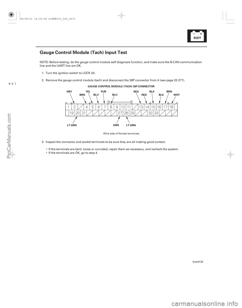
Gauge Control Module (Tach) Input Test
GAUGE CONTROL MODULE (TACH) 36P CONNECTOR
GRY BLU
BRN YEL PUR
REDBLK
WHT
LT GRN GRNRED BLK
BRN
LT GRN
BLU
NOTE: Before testing, do the gauge control module self-diagnosis function, and make sure the B-CAN communication
line and the UART line are OK.
1. Turn the ignition switch to LOCK (0).
2. Remove the gauge control module (tach) and disconnect the 36P connector from it (see page 22-277).
3. Inspect the connector and socket terminals to be sure they are all making good contact. If the terminals are bent, loose or corroded, repair them as necessary, and recheck the system.
IftheterminalsareOK,gotostep4.
(cont’d)
Wire side of female terminals
08/08/21 14:35:58 61SNR030_220_0273
ProCarManuals.com
DYNOMITE -2009-
Page 2224 of 2893
�����(�#�'���������������
�����������������������)���
22-274Gauges
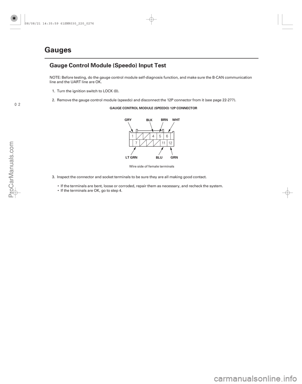
Gauge Control Module (Speedo) Input Test
GAUGE CONTROL MODULE (SPEEDO) 12P CONNECTOR
LT GRN BLUGRN
GRY
BLKBRN
WHT
NOTE: Before testing, do the gauge control module self-diagnosis function, and make sure the B-CAN communication
line and the UART line are OK.
1. Turn the ignition switch to LOCK (0).
2. Remove the gauge control module (speedo) and disconnect the 12P connector from it (see page 22- 277).
3. Inspect the connector and socket terminals to be sure they are all making good contact. If the terminals are bent, loose or corroded, repair them as necessary, and recheck the system.
IftheterminalsareOK,gotostep4.
Wire side of female terminals
08/08/21 14:35:59 61SNR030_220_0276
ProCarManuals.com
DYNOMITE -2009-
Page 2226 of 2893
���
Release Locked odometer mileage to the
original gauge control module.
22-276 Gauges
Rewriting the ODO Data and Transferring the Maintenance")
�µ�µ�µ
�(�#�'���������������
�����������������������)���
Release Locked odometer mileage to the
original gauge control module.
22-276 Gauges
Rewriting the ODO Data and Transferring the Maintenance Minder Data to a
New Gauge Control Module
NOTE:
Obtain a new gauge control module before starting the rewriting process.
Rewriting is not possible on a gauge control module that will not communicate with the HDS.
Make sure that the HDS shows the correct VIN for the car you are working on.
One you have started this procedure, you must complete it before removing the HDS from the DLC.
Connect a battery jump box (not a Battery charger) to insure that correct battery voltage will be maintained.
1. Before replacing the gauge control module, connect the HDS.
2. Select GAUGES from the BODY ELECTRICAL menu display.
3. Select ‘‘Gauge Control M odule Replacement (ODO
rewrite)’’ from the ADJUSTMENT menu, and follow
the instructions on the display to retrieve the ODO
data and the Maintenance Minder information.
4. Replace the gauge control module.
5. Follow the instructions on the display to write the new ODO data and Maintenance Minder data to a
new gauge control module. If the data transfer fails,
refer to the instructions below to release the locked
ODO data. If after you attempt to transfer mileage the odometer
has dashes ( ), garbled, or incorrect value
displayed, do the following start over. The original
gauge control module is going to be unlocked and
restored to its original state.
1. Confirm that you have the latest HDS version of software.
2. Make sure that the HDS shows the correct VIN for the car you are working on.
3. With the ignition switch to LOCK (0), reconnect the original gauge assembly.
4. Completely re-boot the HDS.
5. Clear any stored DTCs.
6. Navigation to Body. Electric/Gauges/Adjustment/Instrument Panel
Replacement.
7. Select ‘‘3. Releasing Locked ODO Data’’.
8. Follow the prompts and the Odometer mileage will be restored.
9. Start over and make sure the screen prompts are followed.
08/08/21 14:35:59 61SNR030_220_0278
ProCarManuals.com
DYNOMITE -2009-
Page 2237 of 2893
����
22-287
Resetting the Moonroof Control Unit
Resetting the moonroof is required when any of the following have occurred: The moonroof was moved manual")
�(�#�'�������������������������������
�!�����)����
22-287
Resetting the Moonroof Control Unit
Resetting the moonroof is required when any of the following have occurred: The moonroof was moved manually while the battery was dead or disconnected.
The moonroof motor was replaced with a new one.
Any of components related to the moonroof were replaced. – Wind deflector
– Moonroof glass
– Moonroof seal
– Moonroof glass bracket
– Moonroof cables, etc.
To reset the moonroof control unit, do these steps: 1. Close the driver’s door, and keep it closed until the procedure is complete.
2. Turn the ignition switch to LOCK (0).
3. Press and hold the tilt switch, and turn the ignition switch to ON (II).
4. Release the tilt switch, and turn the ignition switch to LOCK (0).
5. Repeat steps 3 and 4 four times.
6. Press and hold the moonroof open switch for 3 additional seconds after the moonroof is fully opened.
7. Press and hold the moonroof close switch for 3 additional seconds after the moonroof is fully closed (tilted).
8. Confirm that the moonroof control unit is reset by using the moonroof AUTO OPEN and AUTO CLOSE function.
08/08/21 14:36:04 61SNR030_220_0289
ProCarManuals.com
DYNOMITE -2009-