Page 2126 of 2893
����
���
����
�(�#�'���������������
�����
�
��������� �����)����
Headlight Front Side Marker Light
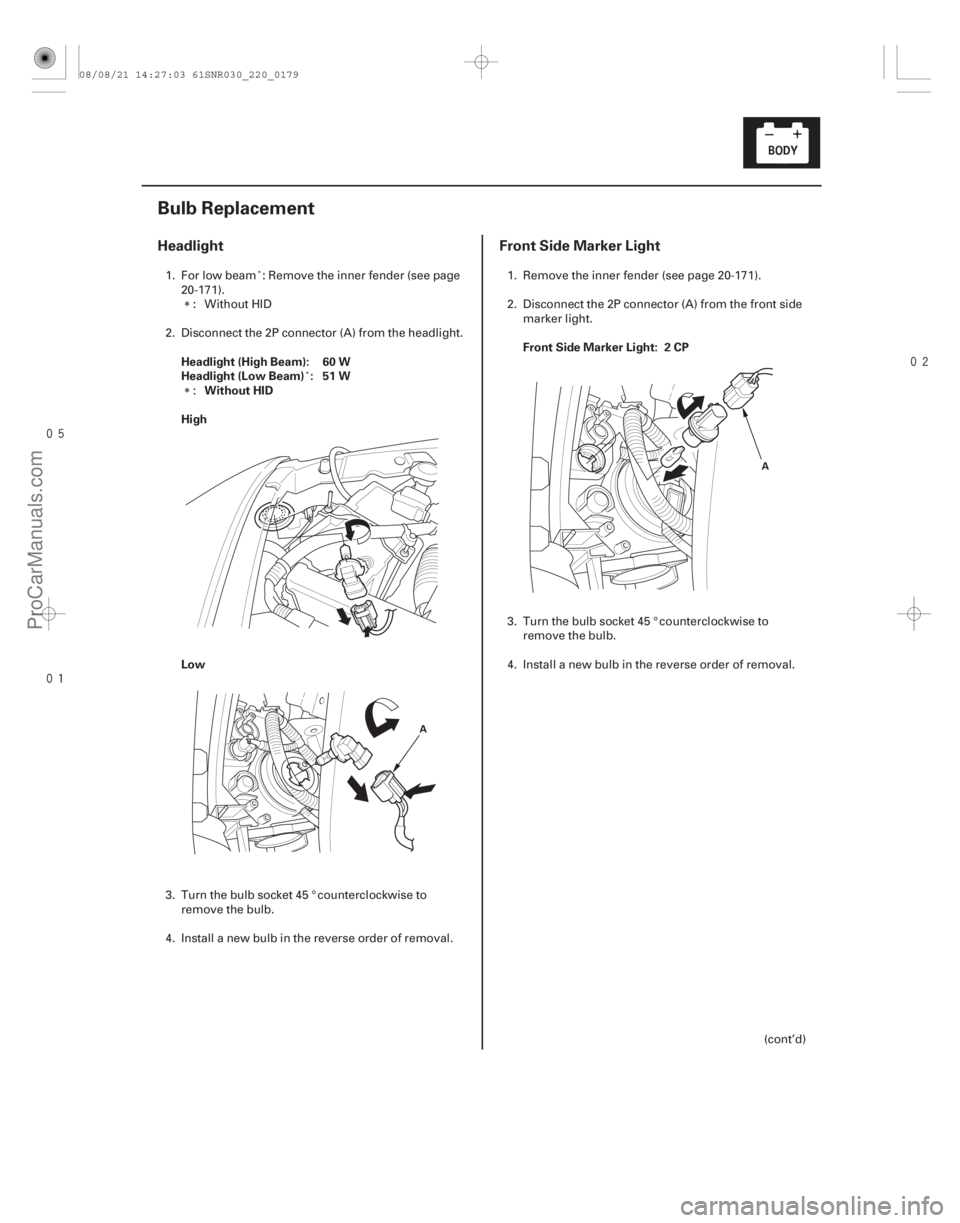
Headlight (High Beam): 60 W
Headlight (Low Beam) : 51 W
Without HID
High
Low Front Side Marker Light: 2 CP
22-177
Bulb Replacement
A
A
1. For low beam : Remove the inner fender (see page
20-171).: Without HID
2. Disconnect the 2P connector (A) from the headlight.
:
3. Turn the bulb socket 45 ° counterclockwise to remove the bulb.
4. Install a new bulb in the reverse order of removal. 1. Remove the inner fender (see page 20-171).
2. Disconnect the 2P connector (A) from the front side
marker light.
3. Turn the bulb socket 45 ° counterclockwise to remove the bulb.
4. Install a new bulb in the reverse order of removal.
(cont’d)
08/08/21 14:27:03 61SNR030_220_0179
ProCarManuals.com
DYNOMITE -2009-
Page 2127 of 2893
��������
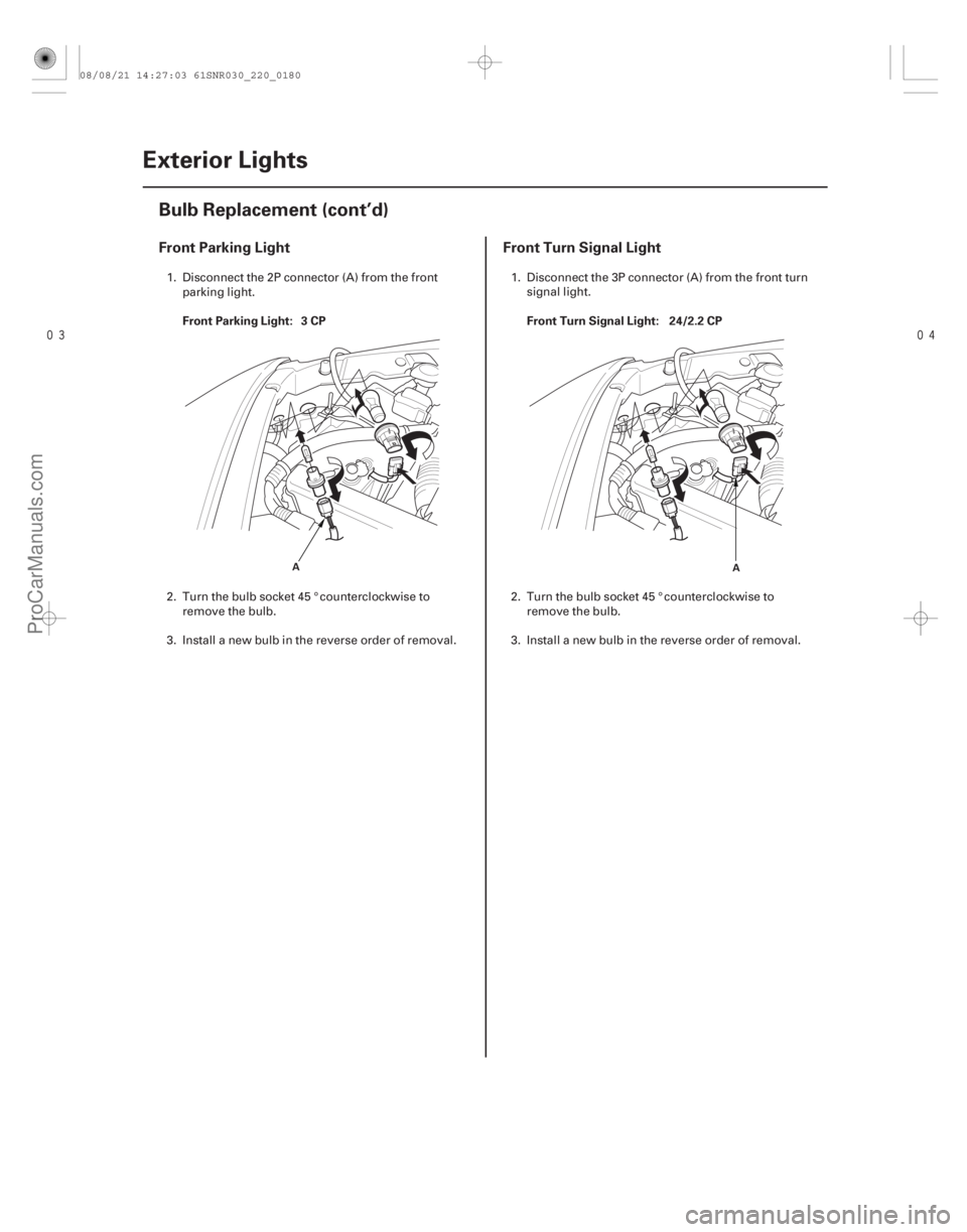
Front Parking LightFront Turn Signal Light
Front Parking Light: 3 CP Front Turn Signal Light: 24/2.2 CP
22-178Exterior Lights
Bulb Replacement (cont’d)
A
A
1. Disconnect the 2P connector (A) from the front
parking light.
2. Turn the bulb socket 45 ° counterclockwise to remove the bulb.
3. Install a new bulb in the reverse order of removal. 1. Disconnect the 3P connector (A) from the front turn
signal light.
2. Turn the bulb socket 45 ° counterclockwise to remove the bulb.
3. Install a new bulb in the reverse order of removal.
08/08/21 14:27:03 61SNR030_220_0180
ProCarManuals.com
DYNOMITE -2009-
Page 2128 of 2893
���
�(�#�'���������������
�����
�����
���
� �����)���� ����
�(�#�'���������������
�����
�����
���
� �����)���
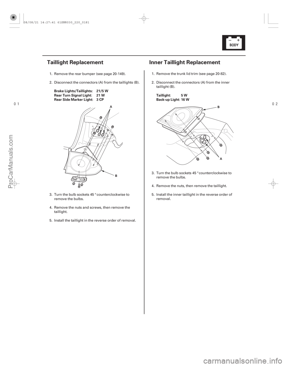
Brake Lights/Taillights: 21/5 W
Rear Turn Signal Light: 21 W
Rear Side Marker Light: 3 CP
Taillight: 5 W
Back-up Light: 16 W
22-17922-179
Taillight Replacement
Inner Taillight Replacement
A
B A
B
1. Remove the rear bumper (see page 20-149).
2. Disconnect the connectors (A) from the ta
illights (B).
3. Turn the bulb sockets 45 ° counterclockwise to remove the bulbs.
4. Remove the nuts and screws, then remove the taillight.
5. Install the taillight in the reverse order of removal. 1. Remove the trunk lid trim (see page 20-82).
2. Disconnect the connectors (A) from the inner
taillight (B).
3. Turn the bulb sockets 45 ° counterclockwise to remove the bulbs.
4. Remove the nuts, then remove the taillight.
5. Install the inner taillight in the reverse order of removal.
08/08/21 14:27:41 61SNR030_220_0181
ProCarManuals.com
DYNOMITE -2009-
Page 2129 of 2893
���� ���
����
�(�#����������������
�
�������
�����
� �����)���
License Plate Light: 5 W
High Mount Brake Light: 21 W
Except TYPE S model
22-18022-1")
���
�(�#�'���������������
���������������
� �����)���� ���
����
�(�#�'���������������
�
�������
�����
� �����)���
License Plate Light: 5 W
High Mount Brake Light: 21 W
Except TYPE S model
22-18022-180Exterior Lights
License Plate Light Replacement High Mount Brake Light
Replacement
A
B
C
A
B
C
A
1. Open the trunk lid, and remove the rear license trim (see page 20-168).
2. Disconnect the 2P connector (A) from the license plate light.
3. Release the bulb socket (B) from the lens (C) by pressing on the tabs.
4. Remove the lens from the trunk lid by pressing on the tabs.
5. Install the license plate light in the reverse order of removal. 1. Open the trunk lid.
2. Disconnect the 2P connector (A) from the high
mount brake light.
3. Turn the bulb socket (B) 45 ° counterclockwise to remove the bulb (C).
4. Remove the rear shelf (see page 20-78).
5. Remove the high mount brake light (A).
6. Install the high mount brake light in the reverse order of removal.
08/08/21 14:27:41 61SNR030_220_0182
ProCarManuals.com
DYNOMITE -2009-
Page 2136 of 2893
����
�µ
�µ
�µ
�µ �µ
�µ
DTC B1280:
YES
NO
When the turn signal switch is in left position
When the turn signal switch is in right position
YES
NO Whe")
�(�#�'��������� �������������.�
�������������)����
�µ
�µ
�µ
�µ �µ
�µ
DTC B1280:
YES
NO
When the turn signal switch is in left position
When the turn signal switch is in right position
YES
NO When the turn signal switch is in left position
When the turn signal switch is in right position
YES
NO
22-186
Exterior Lights
DTC Troubleshooting
Turn Signal Switch Circuit
Malfunction
NOTE: If you are troubleshooting multiple DTCs, be
sure to follow the instructions in B-CAN System
Diagnosis Test Mode A (see page 22-93).
1. Clear the DTCs with the HDS.
2. Turn the ignition switch to LOCK (0) and then back to ON (II).
3. Operate the turn signal switch in left and right positions, and wait for 6 seconds or more.
4. Check for DTCs with the HDS.
Go to step 5.
Intermittent failure, the system is OK at this
time. Check for loose or poor connections.
5. Select LIGHTING from the BODY ELECTRICAL system select menu, then enter DATA LIST.
6. Check each turn signal switch position value with the DATA LIST menu.
Data List Value
Turn Signal Switch (LEFT) ON
Turn Signal Switch (RIGHT) OFF
Data List Value
Turn Signal Switch (LEFT) OFF
Turn Signal Switch (RIGHT) ON
Faulty MICU; replace the under-dash fuse/
relay box (see page 22-66).
Go to step 7. 7. Disconnect the combination light switch 12P
connector.
8. Check each turn signal switch position value with the DATA LIST menu.
Data List Value
Turn Signal Switch (LEFT) ON
Turn Signal Switch (RIGHT) OFF
Data List Value
Turn Signal Switch (LEFT) OFF
Turn Signal Switch (RIGHT) ON
Replace the combination light switch
(see page 22-166).
Go to step 9.
9. Turn the ignition switch to LOCK (0).
10. Disconnect under-dash fuse/relay box connector S (20P).
Is DTC B1280 indicated?
Are all data list values correct? Do bot h v al ues now show i ng OF F ?
08/08/21 14:27:43 61SNR030_220_0188
ProCarManuals.com
DYNOMITE -2009-
Page 2152 of 2893
����
�(�#�'���������������������������������������)����
22-202Entry Lights Control System
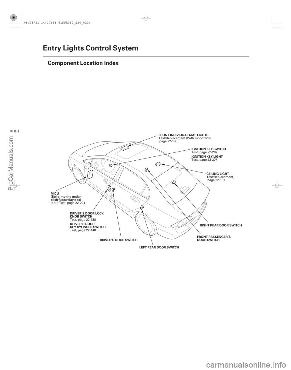
Component Location Index
CEILING LIGHT
FRONT INDIVIDUAL MAP LIGHTS
MICU
(Built into the under-
dash fuse/relay box) IGNITION KEY SWITCH
DRIVER’S DOOR SWITCH LEFT REAR DOOR SWITCH RIGHT REAR DOOR SWITCH
FRONT PASSENGER’S
DOOR SWITCH
DRIVER’S DOOR LOCK
KNOB SWITCH IGNITION KEY LIGHT
DRIVER’S DOOR
KEY CYLINDER SWITCH Test/Replacement,
page 22-197
Test/Replacement (With moonroof),
page 22-196
Input Test, page 22-204 Test, page 22-207
Test, page 22-138 Test, page 22-207
Test, page 22-140
08/08/21 14:27:53 61SNR030_220_0204
ProCarManuals.com
DYNOMITE -2009-
Page 2153 of 2893
����
�µ
�µ
22-203
Circuit Diagram
5 6
R13
ORN
LT BLU
BLK5
7
G501 LOCK
WHT
T23
BRN T24
LT GRN
6
4
UNDER-DASH FUSE/RELAY BOX 7*2
1*1 8*1
9*2K5
G3 D")
����
�(�#�'���������������������������������������)����
�µ
�µ
22-203
Circuit Diagram
5 6
R13
ORN
LT BLU
BLK5
7
G501 LOCK
WHT
T23
BRN T24
LT GRN
6
4
UNDER-DASH FUSE/RELAY BOX 7*2
1*1 8*1
9*2K5
G3 D2
PG
SG
PNKR16
G501 BLK
T34
BLK
G401 F20
E2
GRY
LT BLU LT BLU
CEILING LIGHT BLU
PNK FRONT
INDIVIDUAL
MAP LIGHTS
PNKDOOR
IG1Q6
B-CAN
No. 22 (7.5 A)
No. 2 (IG) (50 A)
No. 1 (BAT) (100 A)
OFFUNDER-DASH FUSE/RELAY BOX
(7.5 A) No. 10
PNK
PNK RED
BLU
BRN E17
E33 R6
G601 BLK
E6
BLK
G602 K4
MICU
E3
E37
GRN LT GRN
G504BLKPNK
1
2
WHT
IG1
BAT
UNDER-HOOD FUSE/RELAY BOX
BATTERY IGNITION SWITCH
IG1 HOT in ON (II)
and START (III)
INTERIOR
LIGHT
SWITCH IMMOBILIZER-
KEYLESS CONTROL
UNIT
DRIVER’S
DOOR
SWITCH
(Closed:
Door open) FRONT
PASSENGER’S
DOOR SWITCH
(Closed:
Door open) LEFT
REAR DOOR
SWITCH
(Closed:
Door open)RIGHT
REAR DOOR
SWITCH
(Closed:
Door open) IGNITION
KEY
SWITCH
(Closed:
Key inserted)IMMOBILIZER-
KEYLESS
CONTROL
UNIT
DRIVER’S
DOOR
LOCK
KNOB
SWITCH
UN-
LOCK
IGNITION
KEY LIGHT
(LED)
H1
D2
1 111 :CANline
*1: ’06 07 models
*2: ’08 09 models
TRANSMITTER
08/08/21 14:27:54 61SNR030_220_0205
ProCarManuals.com
DYNOMITE -2009-
Page 2156 of 2893

6. Reconnect the connectors to the under-da")
Cavity WireTest condition Test: Desired result Possible cause if desired result is not
obtained
22-206Entry Lights Control System
MICU Input Test (cont’d)
6. Reconnect the connectors to the under-dash fuse/relay box, and do these input tests at the following connectors.
If any test indicates a problem, find and correct the cause, then recheck the system.
If all the input tests prove OK, the MICU must be faulty; replace the under-dash fuse/relay box.
E6 BLK Under all conditions Measure the voltage to ground:
There should be less than 0.5 V.Poor ground (G602)
An open in the wire
E33 BLK Under all conditions Measure the voltage to ground: There should be less than 0.5 V.Poor ground (G601)
An open in the wire
F20 BLK Under all conditions Measure the voltage to ground: There should be less than 0.5 V.Poor ground (G401)
An open in the wire
T34 BLK Under all conditions Measure the voltage to ground: There should be less than 0.5 V.Poor ground (G501)
An open in the wire
E37 GRN Driver’s door open Measure the voltage to ground: There should be less than 1 V.Faulty driver’s door switch
An open in the wire
Driver’s door closed Measure the voltage to ground: There should be more than 5 V. Faulty driver’s door switch
A short to ground in the wire
E3 LT GRN Front passenger’s door open Measure the voltage to ground: There should be less than 1 V.Faulty front passenger’s door switch
An open in the wire
Front passenger’s door closed Measure the voltage to ground: There should be more than 5 V. Faulty front passenger’s door switch
A short to ground in the wire
E2 GRY Right rear door open Measure the voltage to ground: There should be less than 1 V.Faulty right rear door switch
An open in the wire
Right rear door closed Measure the voltage to ground: There should be more than 5 V. Faulty right rear door switch
A short to ground in the wire
E17 BRN Left rear door open Measure the voltage to ground: There should be less than 1 V.Faulty left rear door switch
An open in the wire
Left rear door closed Measure the voltage to ground: There should be more than 5 V. Faulty left rear door switch
A short to ground in the wire
R6 PNK Ignition key inserted into the ignition switch Measure the voltage to ground:
There should be less than 1 V. Poor ground (G504)
Faulty ignition key switch
An open in the wire
Ignition switch OFF and ignition
key removed from the ignition
switch Measure the voltage to ground:
There should be more than 5 V.
Faulty ignition key switch
A short to ground in the wire
T23 WHT Driver door lock knob switch unlocked Measure the voltage to ground:
There should be less than 1 V. Poor ground (G501)
Faulty driver door lock knob switch
An open in the wire
Driver door lock knob switch
locked Measure the voltage to ground:
There should be more than 5 V. Faulty driver door lock knob switch
A short to ground in the wire
08/08/21 14:27:54 61SNR030_220_0208
ProCarManuals.com
DYNOMITE -2009-