Page 2157 of 2893
���
�(�#�'�����������������������������
�
�������)���
����
�(�#�'�������������������������������
�������)����
22-20722-207
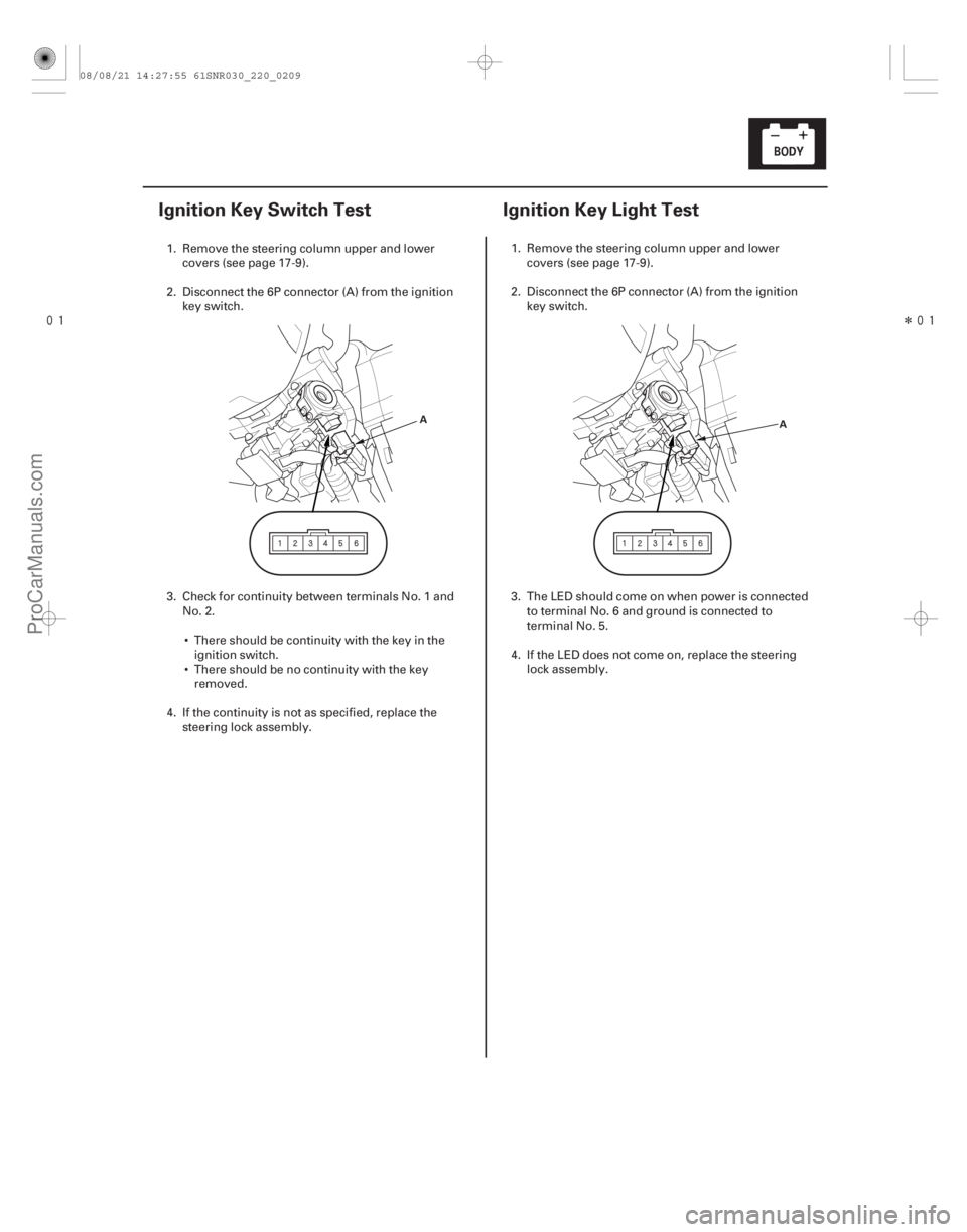
Ignition Key Switch Test Ignition Key Light Test
A
A
1. Remove the steering column upper and lower
covers (see page 17-9).
2. Disconnect the 6P connector (A) from the ignition key switch.
3. Check for continuity between terminals No. 1 and No. 2.
There should be continuity with the key in the ignition switch.
There should be no continuity with the key removed.
4. If the continuity is not as specified, replace the steering lock assembly. 1. Remove the steering column upper and lower
covers (see page 17-9).
2. Disconnect the 6P connector (A) from the ignition key switch.
3. The LED should come on when power is connected to terminal No. 6 and ground is connected to
terminal No. 5.
4. If the LED does not come on, replace the steering lock assembly.
08/08/21 14:27:55 61SNR030_220_0209
ProCarManuals.com
DYNOMITE -2009-
Page 2160 of 2893
�µ
����
�(�#�'���������������������������
�����!�����)����
22-210Power Windows
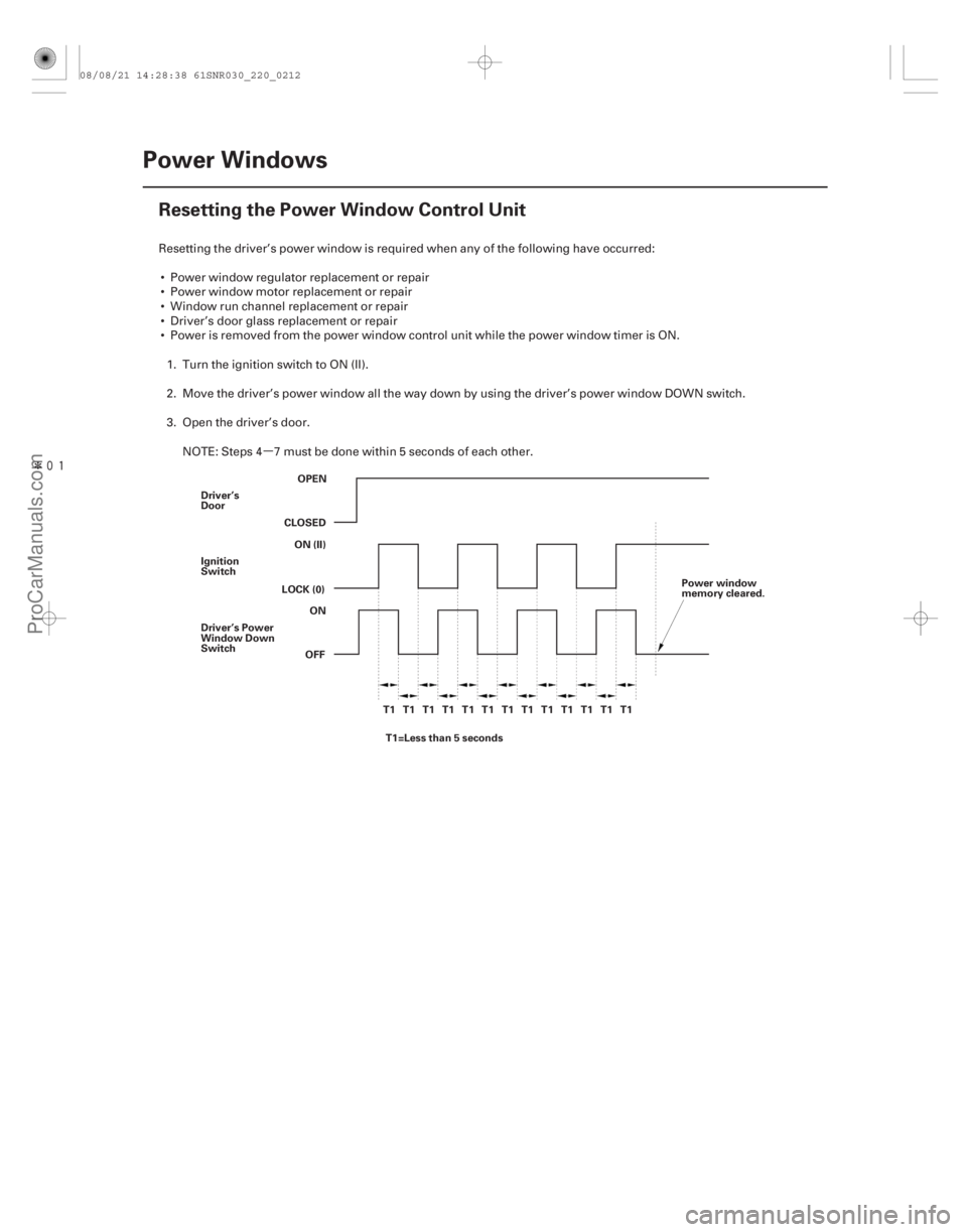
Resetting the Power Window Control Unit
OPEN
CLOSED ON (II)
LOCK (0)
OFFON
Driver’s
Door
Ignition
Switch
Driver’s Power
Window Down
Switch
T1 T1 T1 T1 T1 T1 T1 T1 T1 T1 T1 T1 T1T1=Less than 5 seconds Power window
memory cleared.
Resetting the driver’s power window is required when any of the following have occurred:
Power window regulator replacement or repair
Power window motor replacement or repair
Window run channel replacement or repair
Driver’s door glass replacement or repair
Power is removed from the power window control unit while the power window timer is ON. 1. Turn the ignition switch to ON (II).
2. Move the driver’s power window all the way down by using the driver’s power window DOWN switch.
3. Open the driver’s door.
NOTE: Steps 4 7 must be done within 5 seconds of each other.
08/08/21 14:28:38 61SNR030_220_0212
ProCarManuals.com
DYNOMITE -2009-
Page 2161 of 2893
.
5. Push and hold the driver’s power window DOWN switch.
6. Turn the ignition switch to ON (II).
7. Release the driver’s power window DOWN switch")
�µ
22-211
4. Turn the ignition switch to LOCK (0).
5. Push and hold the driver’s power window DOWN switch.
6. Turn the ignition switch to ON (II).
7. Release the driver’s power window DOWN switch.
8. Repeat step 4 7 three more times.
9. Wait 1 second.
10. Confirm that AUTO UP and AUTO DOWN do not work. If AUTO UP and DOWN work, go back to step 1. If they do not,gotostep11.
11. Move the driver’s power window all the way down by using the driver’s power window DOWN switch.
12. Pull up and hold the driver’s window UP switch until the window reaches the fully closed position, then continue to hold the switch for 1 second.
13. Confirm that the power window control unit is reset by using the driver’s power window AUTO UP and AUTO DOWN functions.
If the window still does not work in AUTO, repeat the procedure several times, paying close attention to the
5 second time limit between steps. If it still does not work, refer to the power window master switch input test
(see page 22-214).
08/08/21 14:28:38 61SNR030_220_0213
ProCarManuals.com
DYNOMITE -2009-
Page 2174 of 2893
����
�µ
�µ
�µ
�µ
�µ
�µ �µ
�µ
�µ
�µ
DTC B1077:
YES
NO
YES
NO
YES
NO YES
NO
YES
NO
22-224Wipers/Washers
DTC Troubleshooting
UNDER-DASH F")
���
����
�(�#�'��������� �������������.�
�������������)����
�µ
�µ
�µ
�µ
�µ
�µ �µ
�µ
�µ
�µ
DTC B1077:
YES
NO
YES
NO
YES
NO YES
NO
YES
NO
22-224Wipers/Washers
DTC Troubleshooting
UNDER-DASH FUSE/RELAY BOX CONNECTOR F (34P)
WINDSHIELD WIPER MOTOR 5P CONNECTOR AS (WHT)
AS (WHT)
WINDSHIELD WIPER MOTOR 5P CONNECTOR AS (WHT)
Windshield Wiper (As) Signal
Error
NOTE: If you are troubleshooting multiple DTCs, be
sure to follow the instructions in B-CAN System
Diagnosis Test Mode A (see page 22-93).
1. Clear the DTCs with the HDS.
2. Turn the ignition switch to LOCK (0), and then back to ON (II).
3. Turn the wiper switch to LOW or HIGH for 15 seconds or more, then turn the switch OFF.
Go to step 4.
Go to step 12.
4. Check for DTCs with the HDS.
Go to step 5.
Intermittent failure. The windshield wiper
system is OK at this time. Check for loose or poor
connections.
5. Turn the ignition switch to LOCK (0).
6. Do the wiper motor test (see page 22-231).
Go to step 7.
Replace the windshield wiper motor
(see page 22-233) and recheck.
7. Disconnect under-dash fuse/relay box connector F (34P) and windshield wiper motor 5P connector. 8. Check for continuity between windshield wiper
motor 5P connector terminal No. 5 and under-dash
fuse/relay box connector F (34P) terminal No. 32.
Go to step 9.
Repair an open in the WHT wire.
9. Check for continuity between windshield wiper motor 5P connector terminal No. 5 and body
ground.
Repair a short in the WHT wire.
Go to step 10.
Wire side of female terminals
Wire side of female terminals
Wire side of female terminals
Do t he w i nd shi el d w i per r un? Is DTC B1077 indicated?
Does t he w i per mot or r un nor mal l y and d oes i tpul se? Is there continuity?
Is there continuity?
08/08/21 14:28:46 61SNR030_220_0226
ProCarManuals.com
DYNOMITE -2009-
Page 2175 of 2893
 UNDER-DASH FUSE/RELAY BOX CONNECTOR F (34P)
LOW (BLU) HI")
��������
����
�µ
�µ
�µ
�µ
�µ
�µ �µ
�µ
�µ
�µ
YES
NO
YES
NO
YES
NO
YES
NO
YES
NO
22-225
WINDSHIELD WIPER MOTOR 5P CONNECTOR
AS (WHT) UNDER-DASH FUSE/RELAY BOX CONNECTOR F (34P)
LOW (BLU) HIGH (YEL)
WINDSHIELD WIPER MOTOR 5P CONNECTOR GND (BLK)
10. Turn the ignition switch to ON (II).
11. Measure the voltage between windshield wipermotor 5P connector terminal No. 5 and body
ground.
Repair a short to power in the WHT wire.
Faulty MICU; replace the under-dash fuse/
relay box.
12. Turn the ignition switch to LOCK (0).
13. Check the No. 38 (30 A) fuse in the under-dash fuse/ relay box.
Go to step 14.
Replace the fuse and recheck the system.
14. Do the wiper motor test (see page 22-231).
Go to step 15.
Replace the windshield wiper motor
(see page 22-233) and recheck.
15. Reconnect the windshield wiper motor 5P connector. 16. Measure the voltage between under-dash fuse/
relay box connector F (34P) terminals No. 18 (LOW)
and No. 19 (HIGH) and body ground with the wiper
switch in corresponding position.
Go to step 17.
Faulty MICU; replace the under-dash fuse/
relay box (see page 22-66).
17. Measure the voltage between windshield wiper motor 5P connector terminal No. 2 and body
ground.
Repair an open in the BLU (LOW) or YEL
(HIGH) wire.
Repair an open in the BLK wire or poor
ground (G 201).
Wire side of female terminals Wire side of female terminals
Wire side of female terminals
Is there voltage? IsthefuseOK?Does t he w i per mot or r un nor mal l y ? Is there battery voltage?
Is t her e l ess t han 0.5 V ?
08/08/21 14:28:46 61SNR030_220_0227
ProCarManuals.com
DYNOMITE -2009-
Page 2176 of 2893
�
��
�µ
�µ
�µ
�µ �µ
�µ
�µ
�µ
DTC B1281:
DTC B1282:
DTC B1283:
DTC B1284:
YES
NO
When the wiper switch is turned OFF Data List Value
YES
NO From te")
�(�#�'��������� �������������.�
�����
�������)�
��
�µ
�µ
�µ
�µ �µ
�µ
�µ
�µ
DTC B1281:
DTC B1282:
DTC B1283:
DTC B1284:
YES
NO
When the wiper switch is turned OFF Data List Value
YES
NO From terminal To terminal
YES
NO
When the wiper switch is turned OFF Data List Value
YES
NO
22-226 Wipers/Washers
DTC Troubleshooting (cont’d)
Windshield Wiper Switch MIST
Position Circuit Malfunction
Windshield Wiper Switch INT
Position Circuit Malfunction
Windshield Wiper Switch LOW
Position Circuit Malfunction
Windshield Wiper Switch HIGH
Position Circuit Malfunction
NOTE: If you are troubleshooting multiple DTCs, be
sure to follow the instructions in B-CAN System
Diagnosis Test Mode A (see page 22-93).
1. Clear the DTCs with the HDS.
2. Turn the ignition switch to LOCK (0) and then back to ON (II).
3. Turn the wiper switch to the MIST, INT, LOW, HIGH, and OFF positions, and wait for at least 6 seconds.
4. Check for DTCs with the HDS.
Go to step 5.
Intermittent failure, the wiper system is OK at
this time. Check for loose or poor connections.
5. Select WIPERS from the BODY ELECTRICAL menu, and enter DATA LIST.
6. Check each wiper switch position value with the DATA LIST menu.
Wiper switch (LOW) OFF
Wiper switch (HIGH) OFF
Wiper switch (MIST) OFF
Wiper switch (INT) OFF Go to step 7.
Go to step 10. 7. Turn the ignition switch to LOCK (0).
8. Disconnect under-dash fuse/relay box connector S
(20P).
9. Check for continuity between under-dash fuse/relay box connector S (20P) terminals as shown:
10 6, 15, 20
15 6, 20
Repair a short between the wires.
Faulty MICU; replace the under-dash fuse/
relay box (see page 22-66).
10. Turn the ignition switch to LOCK (0).
11. Disconnect the 8P connector from the wiper switch.
12. Turn the ignition switch to ON (II).
13. Check each wiper switch position value with the DATA LIST menu.
Wiper switch (LOW) OFF
Wiper switch (HIGH) OFF
Wiper switch (MIST) OFF
Wiper switch (INT) OFF Replace the wiper/washer switch (see page
22-234).
Go to step 14.
I s DT C B12 81, B12 82 , B12 83, or B12 84 i nd i cat ed ?
Are all data list values correct? Is there continuity?
Are all data list values correct?
08/08/21 14:28:47 61SNR030_220_0228
ProCarManuals.com
DYNOMITE -2009-
Page 2177 of 2893

WIP INT/LO SW (ORN)
WIP MIST
SW (GRN) WIP LO/HI
SW (WHT) UNDER-DASH FUSE/RELAY BOX CONNECTOR S (20P)
WIP")
����
�����
�µ
�µ �µ
�µ
YES
NO YES
NO
22-227
UNDER-DASH FUSE/RELAY BOX CONNECTOR S (20P)
WIP INT/LO SW (ORN)
WIP MIST
SW (GRN) WIP LO/HI
SW (WHT) UNDER-DASH FUSE/RELAY BOX CONNECTOR S (20P)
WIP INT/
LO SW
(ORN)
WIP MIST
SW (GRN) WIP LO/HI
SW (WHT)
COMBI GND (BLK)
COMBI GND (BLK)
COMBI GND (BLK)
14. Turn the ignition switch to LOCK (0).
15. Disconnect under-dash fuse/relay box connector S
(20P).
16. Check for continuity between body ground and under-dash fuse/relay box connector S (20P)
terminals No. 10, No. 15, and No. 20 individually.
Repair a short to ground in the wire.
Go to step 17. 17. Check for continuity between under-dash fuse/relay
box connector S (20P) terminal No. 4 and terminals
No. 10, No. 15, and No. 20 individually.
Repair a short between the wires.
Faulty MICU; replace the under-dash fuse/
relay box (see page 22-66).
Wire side of female terminals Wire side of female terminals
Is there continuity?
Is there continuity?
08/08/21 14:28:47 61SNR030_220_0229
ProCarManuals.com
DYNOMITE -2009-
Page 2182 of 2893
���� ���
�(�#������������������������������
�
�������)���
22-23222-232 Wipers/Washers
Washer Motor Test
Washer Fluid Level Switch Test
A
B A
B
1")
����
�(�#�'�������������������������������
�������)���� ���
�(�#�'�����������������������������
�
�������)���
22-23222-232 Wipers/Washers
Washer Motor Test
Washer Fluid Level Switch Test
A
B A
B
1. Remove the right inner fender (see page 20-171).
2. Disconnect the 2P connector (A) from the washermotor (B).
3. Test the motor by connecting battery power to terminal No. 1 and ground terminal No. 2 of the
washer motor. The motor should run.
If the motor does not run, or fails to run smoothly, replace it.
If the motor runs smoothly, but little or no washer fluid is pumped, check for a disconnected
or blocked washer hose, or a clogged washer
motor outlet. 1. Remove the right inner fender (see page 20-171).
2. Disconnect the 2P connector (A) from the washer
fluid level switch (B).
3. Remove the washer fluid level switch from the washer reservoir.
NOTE: Fluid may flow out of the opening.
4. Check for continuity between terminals No. 1 and No. 2 in each float position.
There should be continuity when the float is down.
There should be no continuity when the float is up.
5. If the continuity is not as specified, replace the switch.
Terminal side of
male terminals
08/08/21 14:28:49 61SNR030_220_0234
ProCarManuals.com
DYNOMITE -2009-