Page 180 of 2893
���
��������
�(�#�'�����������
�����������
�����
�
� �����)����
6-36 Cylinder Head
Cylinder Head Cover Removal
B
A
C
1. Remove the engine cover.
2. Remove the four ignition coils (see page 4-21).
3. Disconnect the evaporative emission (EVAP)
canister purge valve connector.
4. Remove the dipstick (A), and disconnect the breather hose (B).
5. Remove two bolts (C) securing the evaporative emission (EVAP) canister purge valve bracket. 6. Remove the cylinder head cover.
08/08/21 14:27:25 61SNR030_060_0036
ProCarManuals.com
DYNOMITE -2009-
Page 182 of 2893

����
���� ���
�(�#�'�����������
��������������������� �����)����
6-386-38 Cylinder Head
Cylinder Head Cover Installation
(cont’d)
Cylinder Head Removal
B
C
A
6x1.0mm
10 N·m
(1.0 kgf·m, 7.2 lbf·ft)
6x1.0mm
12 N·m
(1.2 kgf·m, 8.7 lbf·ft) A
B
8. Install two bolts (A) securing the evaporativeemission (EVAP) canister purge valve bracket.
9. Connect the breather hose (B), and install the dipstick (C).
10. Connect the evaporative emission (EVAP) canister purge valve connector.
11. Install the four ignition coils (see page 4-21).
12. Install the engine cover. NOTE:
Use fender covers to avoid damaging the painted surfaces.
To avoid damaging the wire and terminals, unplug the wiring connectors carefully while holding the
connector portion.
Connect the Honda Diagnostic System (HDS) to the data link connector (DLC) (see step 2 on page 11-3),
and monitor the engine coolant temperature (ECT)
sensor 1. To avoid damaging the cylinder head, wait
until the engine coolant temperature drops below
38 °C (100 °F) before loosening the cylinder head
bolts.
Mark all wiring and hoses to avoid misconnection. Also, be sure that they do not contact other wiring or
hoses, or interfere with other parts.
1. Relieve the fuel pressure (see page 11-322).
2. Drain the engine coolant (see page 10-8).
3. Remove the air cleaner assembly (see page 11-345).
4. Remove the drive belt (see page 4-31).
5. Remove the intake manifold: K20Z2 engine (see page 9-3)
K20Z3 engine (see page 9-7)
6. Remove the exhaust manifold (see page 9-11).
7. Disconnect the evaporative emission (EVAP) canister hose (A) and the brake booster vacuum
hose (B).
08/08/21 14:27:27 61SNR030_060_0038
ProCarManuals.com
DYNOMITE -2009-
Page 183 of 2893

����
���� ���
�(�#�'�����������
��������������������� �����)����
6-386-38 Cylinder Head
Cylinder Head Cover Installation
(cont’d)
Cylinder Head Removal
B
C
A
6x1.0mm
10 N·m
(1.0 kgf·m, 7.2 lbf·ft)
6x1.0mm
12 N·m
(1.2 kgf·m, 8.7 lbf·ft) A
B
8. Install two bolts (A) securing the evaporativeemission (EVAP) canister purge valve bracket.
9. Connect the breather hose (B), and install the dipstick (C).
10. Connect the evaporative emission (EVAP) canister purge valve connector.
11. Install the four ignition coils (see page 4-21).
12. Install the engine cover. NOTE:
Use fender covers to avoid damaging the painted surfaces.
To avoid damaging the wire and terminals, unplug the wiring connectors carefully while holding the
connector portion.
Connect the Honda Diagnostic System (HDS) to the data link connector (DLC) (see step 2 on page 11-3),
and monitor the engine coolant temperature (ECT)
sensor 1. To avoid damaging the cylinder head, wait
until the engine coolant temperature drops below
38 °C (100 °F) before loosening the cylinder head
bolts.
Mark all wiring and hoses to avoid misconnection. Also, be sure that they do not contact other wiring or
hoses, or interfere with other parts.
1. Relieve the fuel pressure (see page 11-322).
2. Drain the engine coolant (see page 10-8).
3. Remove the air cleaner assembly (see page 11-345).
4. Remove the drive belt (see page 4-31).
5. Remove the intake manifold: K20Z2 engine (see page 9-3)
K20Z3 engine (see page 9-7)
6. Remove the exhaust manifold (see page 9-11).
7. Disconnect the evaporative emission (EVAP) canister hose (A) and the brake booster vacuum
hose (B).
08/08/21 14:27:27 61SNR030_060_0038
ProCarManuals.com
DYNOMITE -2009-
Page 1148 of 2893

����
���� ����
�(�#�'�������
���
�����������
�������
� �����)����
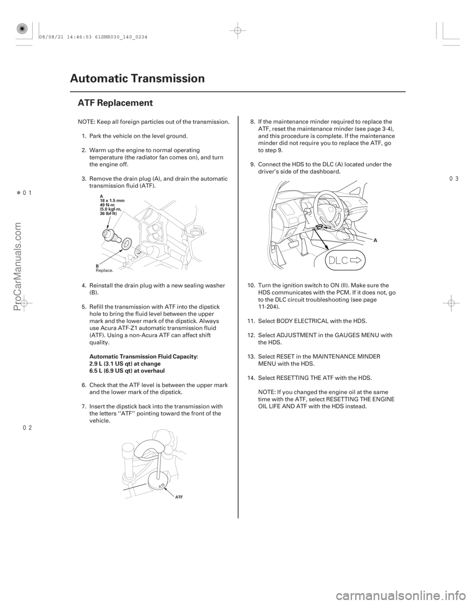
Automatic Transmission Fluid Capacity:
2.9 L (3.1 US qt) at change
6.5 L (6.9 US qt) at overhaul
14-232 Automatic Transmission
ATF Replacement
A
18 x 1.5 mm
49 N·m
(5.0 kgf·m,
36 lbf·ft)
B
ATF
A
NOTE: Keep all foreign particles out of the transmission. 1. Park the vehicle on the level ground.
2. Warm up the engine to normal operating temperature (the radiator fan comes on), and turn
the engine off.
3. Remove the drain plug (A), and drain the automatic transmission fluid (ATF).
4. Reinstall the drain plug with a new sealing washer (B).
5. Refill the transmission with ATF into the dipstick hole to bring the fluid level between the upper
mark and the lower mark of the dipstick. Always
use Acura ATF-Z1 automatic transmission fluid
(ATF). Using a non-Acura ATF can affect shift
quality.
6. Check that the ATF level is between the upper mark
and the lower mark of the dipstick.
7. Insert the dipstick back into the transmission with the letters ‘‘ATF’’ pointing toward the front of the
vehicle. 8. If the maintenance minder required to replace the
ATF, reset the maintenance minder (see page 3-4),
and this procedure is complete. If the maintenance
minder did not require you to replace the ATF, go
to step 9.
9. Connect the HDS to the DLC (A) located under the driver’s side of the dashboard.
10. Turn the ignition switch to ON (II). Make sure the HDS communicates with the PCM. If it does not, go
to the DLC circuit troubleshooting (see page
11-204).
11. Select BODY ELECTRICAL with the HDS.
12. Select ADJUSTMENT in the GAUGES MENU with the HDS.
13. Select RESET in the MAINTENANCE MINDER MENU with the HDS.
14. Select RESETTING THE ATF with the HDS.
NOTE: If you changed the engine oil at the same
time with the ATF, select RESETTING THE ENGINE
OIL LIFE AND ATF with the HDS instead.
Replace.
08/08/21 14:46:53 61SNR030_140_0234
ProCarManuals.com
DYNOMITE -2009-