Page 3861 of 5135
B09793
Convex
Concave
B08249
Upward
B08253
± ENGINE MECHANICALPARTIAL ENGINE ASSY (1CD±FTV)
14±19
1CD±FTV ENGINE REPAIR MANUAL (RM927E)
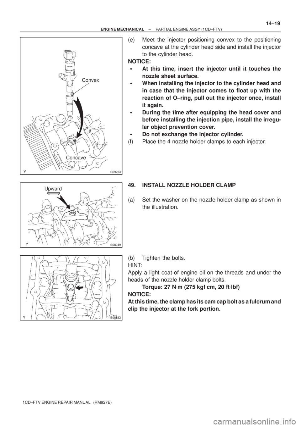
(e) Meet the injector positioning convex to the positioning
concave at the cylinder head side and install the injector
to the cylinder head.
NOTICE:
�At this time, insert the injector until it touches the
nozzle sheet surface.
�When installing the injector to the cylinder head and
in case that the injector comes to float up with the
reaction of O±ring, pull out the injector once, install
it again.
�During the time after equipping the head cover and
before installing the injection pipe, install the irregu-
lar object prevention cover.
�Do not exchange the injector cylinder.
(f) Place the 4 nozzle holder clamps to each injector.
49. INSTALL NOZZLE HOLDER CLAMP
(a) Set the washer on the nozzle holder clamp as shown in
the illustration.
(b) Tighten the bolts.
HINT:
Apply a light coat of engine oil on the threads and under the
heads of the nozzle holder clamp bolts.
Torque: 27 N�m (275 kgf�cm, 20 ft�lbf)
NOTICE:
At this time, the clamp has its cam cap bolt as a fulcrum and
clip the injector at the fork portion.
Page 3862 of 5135
90�
180�
B08307
B08311
B08312
Plug
GasketOverflow Screw
Ball Spring 14±20
± ENGINE MECHANICALPARTIAL ENGINE ASSY (1CD±FTV)
1CD±FTV ENGINE REPAIR MANUAL (RM927E)
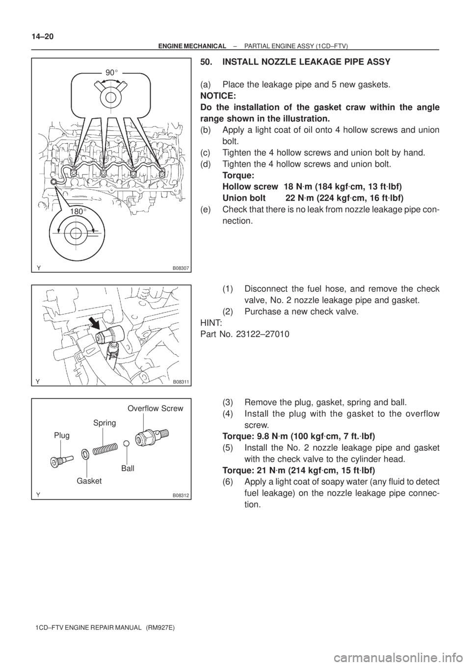
50. INSTALL NOZZLE LEAKAGE PIPE ASSY
(a) Place the leakage pipe and 5 new gaskets.
NOTICE:
Do the installation of the gasket craw within the angle
range shown in the illustration.
(b) Apply a light coat of oil onto 4 hollow screws and union
bolt.
(c) Tighten the 4 hollow screws and union bolt by hand.
(d) Tighten the 4 hollow screws and union bolt.
Torque:
Hollow screw 18 N�m (184 kgf�cm, 13 ft�lbf)
Union bolt 22 N�m (224 kgf�cm, 16 ft�lbf)
(e) Check that there is no leak from nozzle leakage pipe con-
nection.
(1) Disconnect the fuel hose, and remove the check
valve, No. 2 nozzle leakage pipe and gasket.
(2) Purchase a new check valve.
HINT:
Part No. 23122±27010
(3) Remove the plug, gasket, spring and ball.
(4) Install the plug with the gasket to the overflow
screw.
Torque: 9.8 N�m (100 kgf�cm, 7 ft.�lbf)
(5) Install the No. 2 nozzle leakage pipe and gasket
with the check valve to the cylinder head.
Torque: 21 N�m (214 kgf�cm, 15 ft�lbf)
(6) Apply a light coat of soapy water (any fluid to detect
fuel leakage) on the nozzle leakage pipe connec-
tion.
Page 3864 of 5135
190AI±01
A62720
Drive End Frame Assy Generator w/ Clutch Pulley
Alternator Pulley CapGenerator Rotor Assy
Rear End Cover
Sub±Assy Rear Seal Plate
Generator Brush
Holder Assy
Front Seal
Plate
Alternator Coil Assy
N´m (kgf´cm, ft´lbf)
: Specified torque
5.8 (59, 51 in.´lbf)
1.8 (18, 16 in.´lbf)
4.6 (47, 41 in.´lbf)
± STARTING & CHARGINGGENERATOR ASSY(130A) (1CD±FTV)
19±31
1CD±FTV ENGINE REPAIR MANUAL (RM927E)
GENERATOR ASSY(130A) (1CD±FTV)
COMPONENTS
Page 3874 of 5135
05±14
±
DIAGNOSTICS SFI SYSTEM(1ZZ±FE/3ZZ±FE)
AVENSIS REPAIR MANUAL (RM1018E)
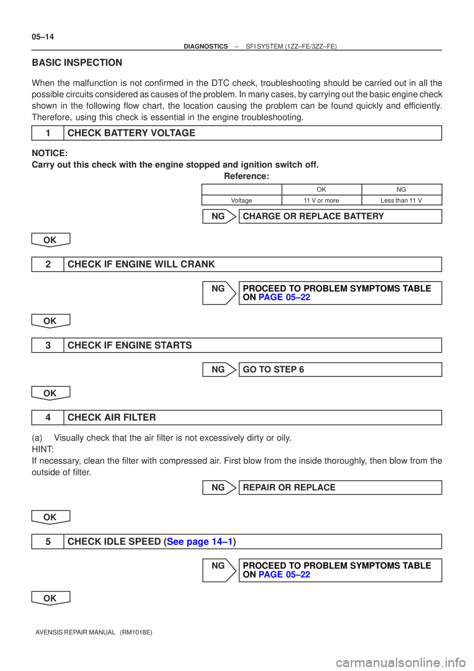
BASIC INSPECTION
When the malfunction is not confirmed in the DTC check, troubleshooting \
should be carried out in all the
possible circuits considered as causes of the problem. In many cases, by carrying out the basic engine check
shown in the following flow chart, the location causing the problem can be found quickly and efficiently.
Therefore, using this check is essential in the engine troubleshooting.
1CHECK BATTERY VOLTAGE
NOTICE:
Carry out this check with the engine stopped and ignition switch off. Reference:
OKNG
Voltage11 V or moreLess than 11 V
NGCHARGE OR REPLACE BATTERY
OK
2CHECK IF ENGINE WILL CRANK
NGPROCEED TO PROBLEM SYMPTOMS TABLE ON PAGE 05±22
OK
3CHECK IF ENGINE STARTS
NGGO TO STEP 6
OK
4CHECK AIR FILTER
(a)Visually check that the air filter is not excessively dirty or oily.
HINT:
If necessary, clean the filter with compressed air. First blow from the inside thoroughly, then blow from the
outside of filter. NGREPAIR OR REPLACE
OK
5CHECK IDLE SPEED (See page 14±1)
NGPROCEED TO PROBLEM SYMPTOMS TABLE ON PAGE 05±22
OK
Page 3877 of 5135
05±174
±
DIAGNOSTICS SFI SYSTEM(1AZ±FE)
AVENSIS REPAIR MANUAL (RM1018E)
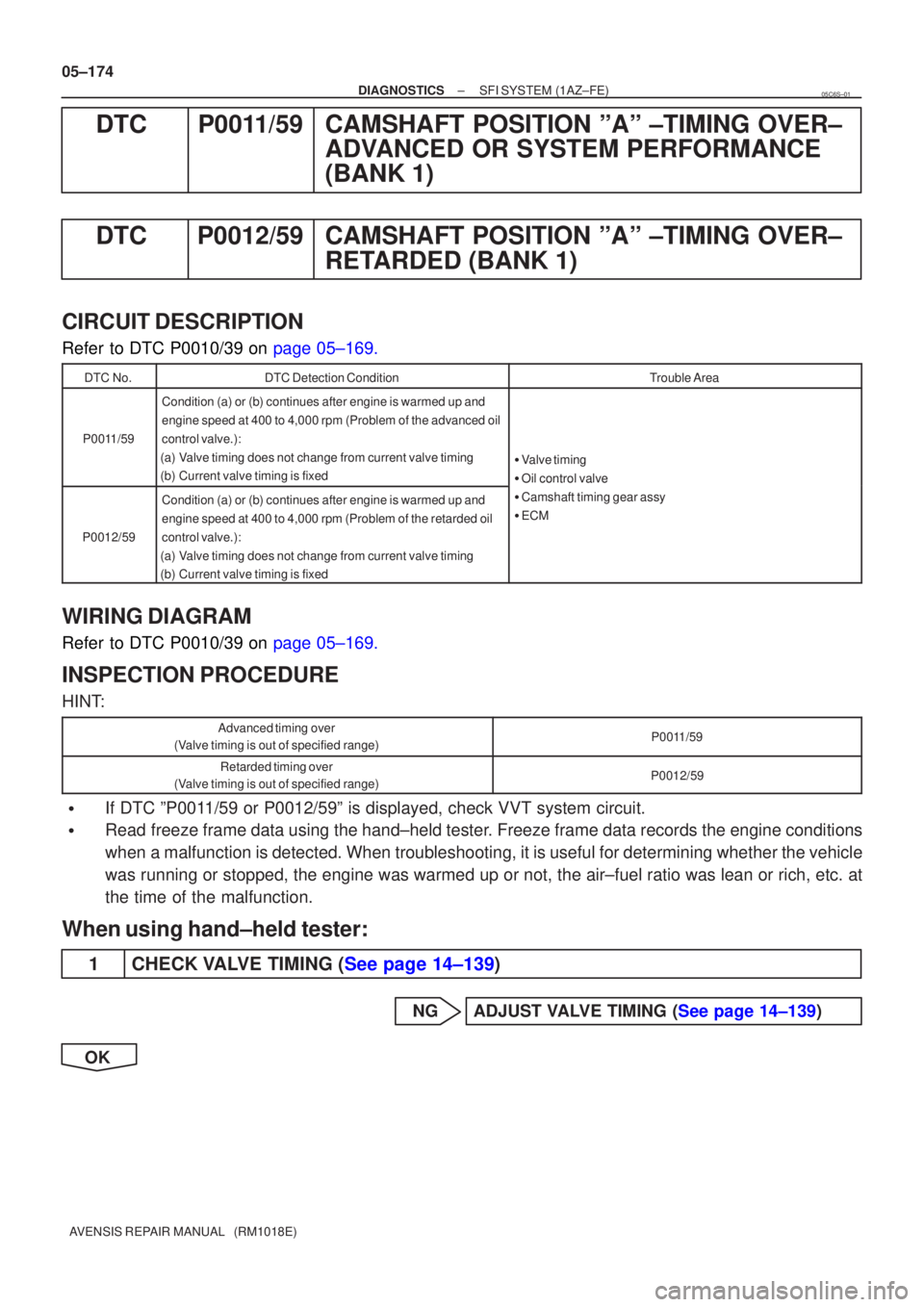
DTCP0011/59CAMSHAFT POSITION ºAº ±TIMING OVER± ADVANCED OR SYSTEM PERFORMANCE
(BANK 1)
DTCP0012/59CAMSHAFT POSITION ºAº ±TIMING OVER± RETARDED (BANK 1)
CIRCUIT DESCRIPTION
Refer to DTC P0010/39 on page 05±169.
DTC No.DTC Detection ConditionTrouble Area
P0011/59
Condition (a) or (b) continues after engine is warmed up and
engine speed at 400 to 4,000 rpm (Problem of the advanced oil
control valve.):
(a)Valve timing does not change from current valve timing
(b)Current valve timing is fixed
� Valve timing
� Oil control valve
P0012/59
Condition (a) or (b) continues after engine is warmed up and
engine speed at 400 to 4,000 rpm (Problem of the retarded oil
control valve.):
(a)Valve timing does not change from current valve timing
(b)Current valve timing is fixed
Oil control valve
� Camshaft timing gear assy
� ECM
WIRING DIAGRAM
Refer to DTC P0010/39 on page 05±169.
INSPECTION PROCEDURE
HINT:
Advanced timing over
(Valve timing is out of specified range)P0011/59
Retarded timing over
(Valve timing is out of specified range)P0012/59
�If DTC ºP0011/59 or P0012/59º is displayed, check VVT system circuit.
�Read freeze frame data using the hand±held tester. Freeze frame data records the engine conditions
when a malfunction is detected. When troubleshooting, it is useful for deter\
mining whether the vehicle
was running or stopped, the engine was warmed up or not, the air±fuel ra\
tio was lean or rich, etc. at
the time of the malfunction.
When using hand±held tester:
1CHECK VALVE TIMING (See page 14±139)
NGADJUST VALVE TIMING (See page 14±139)
OK
05C6S±01
Page 3878 of 5135
± DIAGNOSTICSSFI SYSTEM (1AZ±FE)
05±175
AVENSIS REPAIR MANUAL (RM1018E)
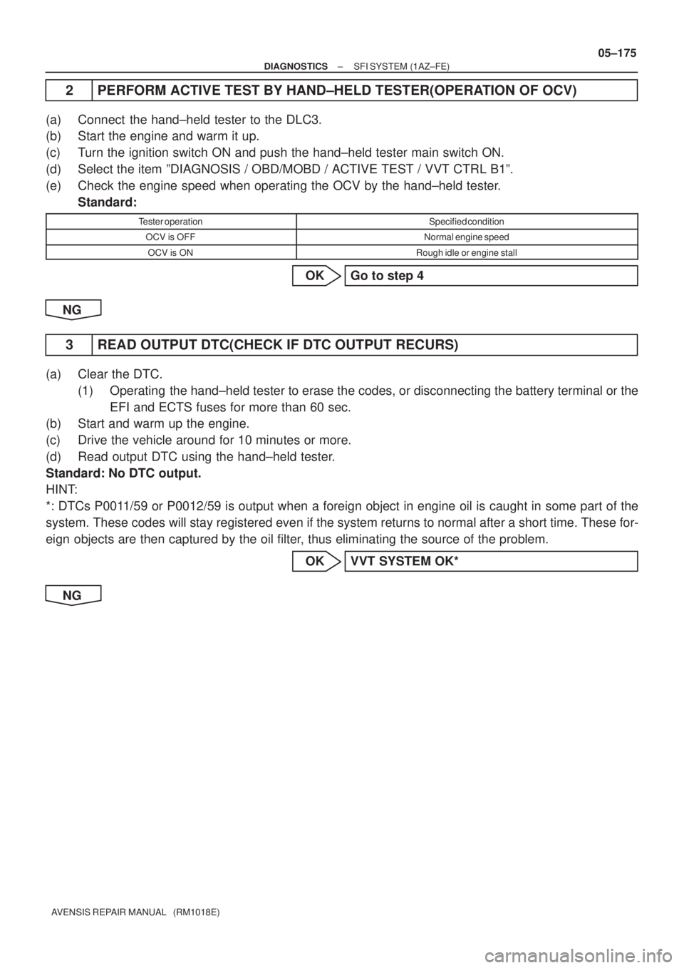
2 PERFORM ACTIVE TEST BY HAND±HELD TESTER(OPERATION OF OCV)
(a) Connect the hand±held tester to the DLC3.
(b) Start the engine and warm it up.
(c) Turn the ignition switch ON and push the hand±held tester main switch ON.
(d) Select the item ºDIAGNOSIS / OBD/MOBD / ACTIVE TEST / VVT CTRL B1º.
(e) Check the engine speed when operating the OCV by the hand±held tester.
Standard:
Tester operationSpecified condition
OCV is OFFNormal engine speed
OCV is ONRough idle or engine stall
OK Go to step 4
NG
3 READ OUTPUT DTC(CHECK IF DTC OUTPUT RECURS)
(a) Clear the DTC.
(1) Operating the hand±held tester to erase the codes, or disconnecting the battery terminal or the
EFI and ECTS fuses for more than 60 sec.
(b) Start and warm up the engine.
(c) Drive the vehicle around for 10 minutes or more.
(d) Read output DTC using the hand±held tester.
Standard: No DTC output.
HINT:
*: DTCs P0011/59 or P0012/59 is output when a foreign object in engine oil is caught in some part of the
system. These codes will stay registered even if the system returns to normal after a short time. These for-
eign objects are then captured by the oil filter, thus eliminating the source of the problem.
OK VVT SYSTEM OK*
NG
Page 3879 of 5135
A79111
OCV Signal Waveform1 msec./Division 5 V/
Division
GND
(A)(A) (A)
E13
OC1 +OC1±
05±176
±
DIAGNOSTICS SFI SYSTEM(1AZ±FE)
AVENSIS REPAIR MANUAL (RM1018E)
4CHECK ECM(OCV SIGNAL)
(a)Inspection using the oscilloscope.
(b)During idling, check the waveform between the terminals of the E13 ECM connector.
Standard:
Symbols (Terminal No.)Specified condition
OC1+ (E13±15) ± OC1± (E13±14)Correct waveform is as shown
HINT:
The waveform frequency (A) is lengthened as the engine speed
becomes higher.
NGCHECK AND REPLACE ECM (See page 01±32)
OK
5CHECK OIL CONTROL VALVE FILTER
NGREPLACE OIL CONTROL VALVE FILTER
OK
6CHECK CAMSHAFT TIMING OIL CONTROL VALVE ASSY(OCV) (See page 10±20)
OKGo to step 8
NG
7REPLACE CAMSHAFT TIMING OIL CONTROL VALVE ASSY(OCV)
GO
8CHECK CAMSHAFT TIMING GEAR ASSY (See page 14±171)
OK Go to step 10
NG
Page 3880 of 5135
±
DIAGNOSTICS SFI SYSTEM(1AZ±FE)
05±177
AVENSIS REPAIR MANUAL (RM1018E)
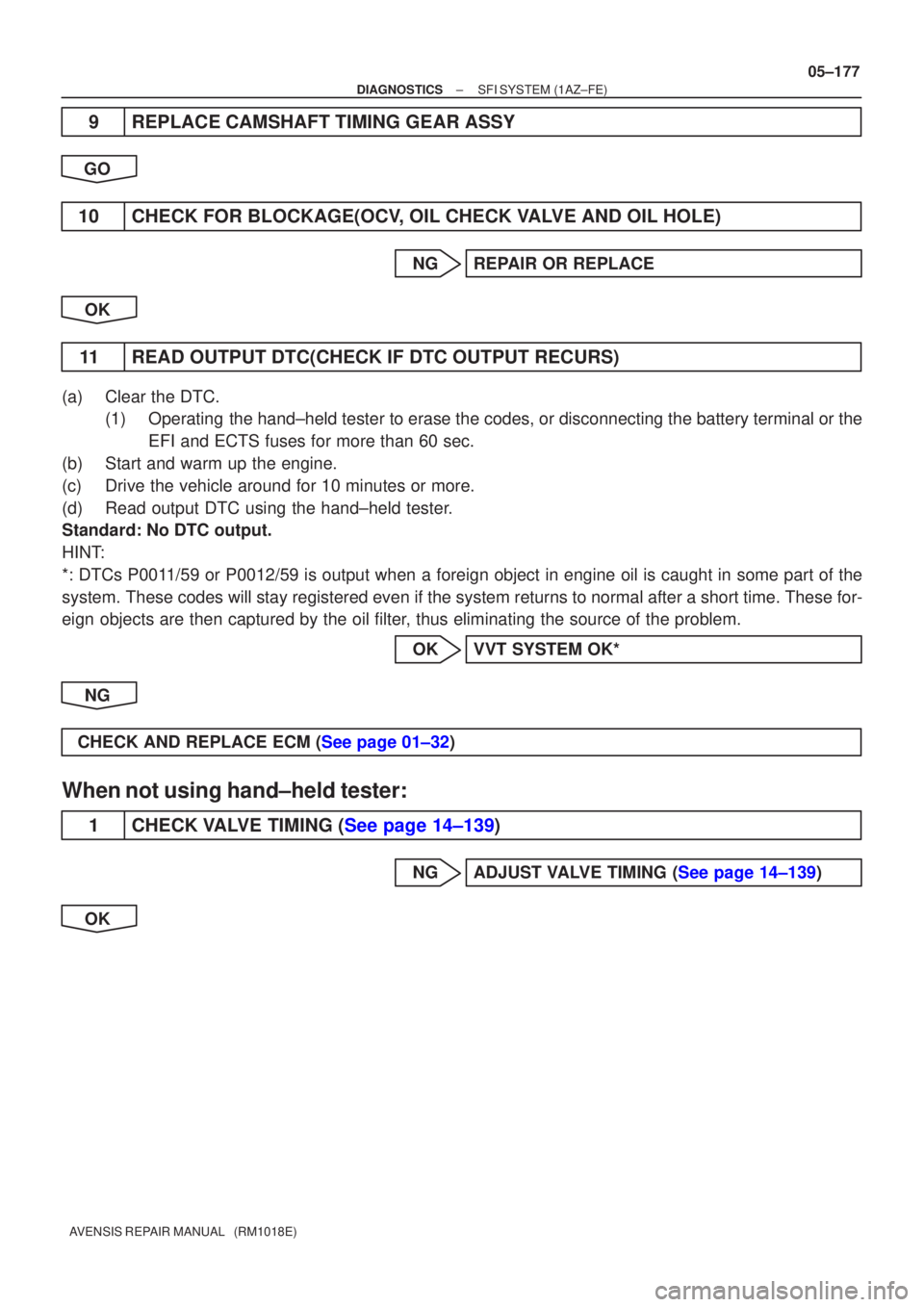
9REPLACE CAMSHAFT TIMING GEAR ASSY
GO
10CHECK FOR BLOCKAGE(OCV, OIL CHECK VALVE AND OIL HOLE)
NGREPAIR OR REPLACE
OK
11READ OUTPUT DTC(CHECK IF DTC OUTPUT RECURS)
(a)Clear the DTC. (1)Operating the hand±held tester to erase the codes, or disconnecting the batter\
y terminal or the
EFI and ECTS fuses for more than 60 sec.
(b)Start and warm up the engine.
(c)Drive the vehicle around for 10 minutes or more.
(d)Read output DTC using the hand±held tester.
Standard: No DTC output.
HINT:
*: DTCs P0011/59 or P0012/59 is output when a foreign object in engine oil is caught\
in some part of the
system. These codes will stay registered even if the system returns to normal a\
fter a short time. These for-
eign objects are then captured by the oil filter, thus eliminating the source of the problem.
OKVVT SYSTEM OK*
NG
CHECK AND REPLACE ECM (See page 01±32)
When not using hand±held tester:
1CHECK VALVE TIMING (See page 14±139)
NGADJUST VALVE TIMING (See page 14±139)
OK