Page 3899 of 5135
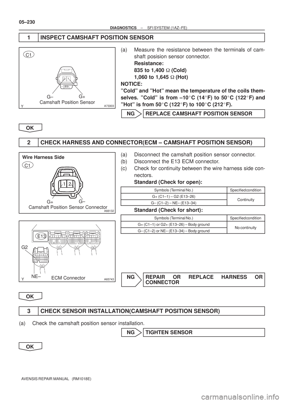
A73303
G±G+
Camshaft Position Sensor C1
��
A66132
G+G±
Camshaft Position Sensor Connector Wire Harness Side
C1
A65743NE± G2
E13
ECM Connector
05±230
± DIAGNOSTICSSFI SYSTEM (1AZ±FE)
AVENSIS REPAIR MANUAL (RM1018E)
1 INSPECT CAMSHAFT POSITION SENSOR
(a) Measure the resistance between the terminals of cam-
shaft posision sensor connector.
Resistance:
835 to 1,400 � (Cold)
1,060 to 1,645 �(Hot)
NOTICE:
ºColdº and ºHotº mean the temperature of the coils them-
selves. ºColdº is from ±10�C (14�F) to 50�C (122�F) and
ºHotº is from 50�C (122�F) to 100�C (212�F).
NG REPLACE CAMSHAFT POSITION SENSOR
OK
2 CHECK HARNESS AND CONNECTOR(ECM ± CAMSHAFT POSITION SENSOR)
(a) Disconnect the camshaft position sensor connector.
(b) Disconnect the E13 ECM connector.
(c) Check for continuity between the wire harness side con-
nectors.
Standard (Check for open):
Symbols (Terminal No.)Specified condition
G+ (C1±1) ± G2 (E13±26)ContinuityG± (C1±2) ± NE± (E13±34)Continuity
Standard (Check for short):
Symbols (Terminal No.)Specified condition
G+ (C1±1) or G2+ (E13±26) ± Body groundNo continuityG± (C1±2) or NE± (E13±34) ± Body groundNo continuity
NG REPAIR OR REPLACE HARNESS OR
CONNECTOR
OK
3 CHECK SENSOR INSTALLATION(CAMSHAFT POSITION SENSOR)
(a) Check the camshaft position sensor installation.
NG TIGHTEN SENSOR
OK
Page 3931 of 5135
05±436
± DIAGNOSTICSSFI SYSTEM (1AZ±FSE)
AVENSIS REPAIR MANUAL (RM1018E)
DTC P0340 CAMSHAFT POSITION SENSOR ºAº
CIRCUIT (BANK 1 OR SINGLE SENSOR)
DTC P0341 CAMSHAFT POSITION SENSOR ºAº
CIRCUIT RANGE/PERFORMANCE (BANK 1
SINGLE SENSOR)
CIRCUIT DESCRIPTION
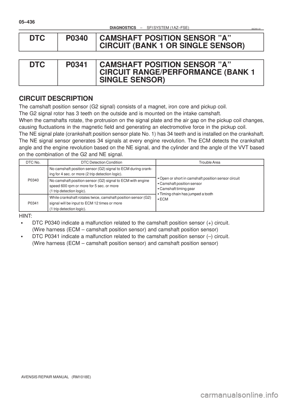
The camshaft position sensor (G2 signal) consists of a magnet, iron core and pickup coil.
The G2 signal rotor has 3 teeth on the outside and is mounted on the intake camshaft.
When the camshafts rotate, the protrusion on the signal plate and the air gap on the pickup coil changes,
causing fluctuations in the magnetic field and generating an electromotive force in the pickup coil.
The NE signal plate (crankshaft position sensor plate No. 1) has 34 teeth and is installed on the crankshaft.
The NE signal sensor generates 34 signals at every engine revolution. The ECM detects the crankshaft
angle and the engine revolution based on the NE signal, and the cylinder and the angle of the VVT based
on the combination of the G2 and NE signal.
DTC No.DTC Detection ConditionTrouble Area
No camshaft position sensor (G2) signal to ECM during crank-
ing for 4 sec. or more (2 trip detection logic).
O h t i h ft iti i itP0340No camshaft position sensor (G2) signal to ECM with engine
speed 600 rpm or more for 5 sec. or more
(1 trip detection logic).�Open or short in camshaft position sensor circuit
�Camshaft position sensor
�Camshaft timing gear
�Timing chain has jumped a tooth
P0341
While crankshaft rotates twice, camshaft position sensor (G2)
signal will be input to ECM 12 times or more
(1 trip detection logic).�Timing chain has jumped a tooth
�ECM
HINT:
�DTC P0340 indicate a malfunction related to the camshaft position sensor (+) circuit.
(Wire harness (ECM ± camshaft position sensor) and camshaft position sensor)
�DTC P0341 indicate a malfunction related to the camshaft position sensor (±) circuit.
(Wire harness (ECM ± camshaft position sensor) and camshaft position sensor)
05CKK±01
Page 3932 of 5135
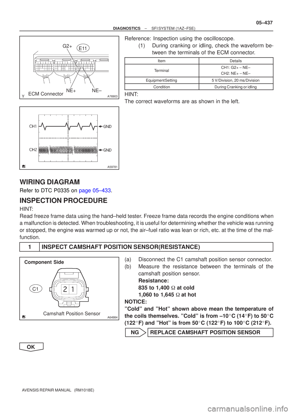
A76903
NE+
G2+
NE±ECM Connector E11
A59781
A64984Camshaft Position Sensor
Component Side
C1
±
DIAGNOSTICS SFI SYSTEM(1AZ±FSE)
05±437
AVENSIS REPAIR MANUAL (RM1018E)
Reference: Inspection using the oscilloscope.
(1)During cranking or idling, check the waveform be-tween the terminals of the ECM connector.
ItemDetails
TerminalCH1: G2+ ± NE±
CH2: NE+ ± NE±
Equipment Setting5 V/Division, 20 ms/Division
ConditionDuring Cranking or idling
HINT:
The correct waveforms are as shown in the left.
WIRING DIAGRAM
Refer to DTC P0335 on page 05±433.
INSPECTION PROCEDURE
HINT:
Read freeze frame data using the hand±held tester. Freeze frame data records the engine conditions when
a malfunction is detected. When troubleshooting, it is useful for determi\
ning whether the vehicle was running
or stopped, the engine was warmed up or not, the air±fuel ratio was lea\
n or rich, etc. at the time of the mal-
function.
1 INSPECT CAMSHAFT POSITION SENSOR(RESISTANCE)
(a) Disconnect the C1 camshaft position sensor connector.
(b) Measure the resistance between the terminals of the camshaft position sensor.
Resistance:
835 to 1,400 � at cold
1,060 to 1,645 �at hot
NOTICE:
ºColdº and ºHotº shown above mean the temperature of
the coils themselves. ºColdº is from ±10 �C (14 �F) to 50 �C
(122 �F) and ºHotº is from 50 �C (122 �F) to 100 �C (212 �F).
NG REPLACE CAMSHAFT POSITION SENSOR
OK
Page 3937 of 5135
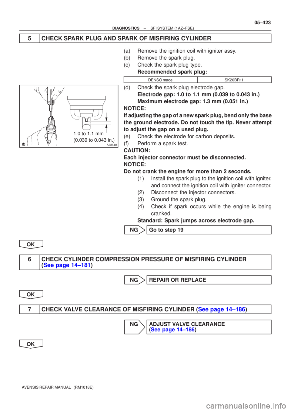
A78640
1.0 to 1.1 mm
(0.039 to 0.043 in.)
±
DIAGNOSTICS SFI SYSTEM(1AZ±FSE)
05±423
AVENSIS REPAIR MANUAL (RM1018E)
5CHECK SPARK PLUG AND SPARK OF MISFIRING CYLINDER
(a)Remove the ignition coil with igniter assy.
(b)Remove the spark plug.
(c)Check the spark plug type.
Recommended spark plug:
DENSO madeSK20BR11
(d)Check the spark plug electrode gap.Electrode gap: 1.0 to 1.1 mm (0.039 to 0.043 in.)
Maximum electrode gap: 1.3 mm (0.051 in.)
NOTICE:
If adjusting the gap of a new spark plug, bend only the base
the ground electrode. Do not touch the tip. Never attempt
to adjust the gap on a used plug.
(e)Check the electrode for carbon deposits.
(f)Perform a spark test.
CAUTION:
Each injector connector must be disconnected.
NOTICE:
Do not crank the engine for more than 2 seconds. (1)Install the spark plug to the ignition coil with igniter,and connect the ignition coil with igniter connector.
(2)Disconnect the injector connectors.
(3)Ground the spark plug.
(4)Check if spark occurs while the engine is being
cranked.
Standard: Spark jumps across electrode gap.
NGGo to step 19
OK
6CHECK CYLINDER COMPRESSION PRESSURE OF MISFIRING CYLINDER (See page 14±181)
NGREPAIR OR REPLACE
OK
7CHECK VALVE CLEARANCE OF MISFIRING CYLINDER (See page 14±186)
NG ADJUST VALVE CLEARANCE (See page 14±186)
OK
Page 3941 of 5135
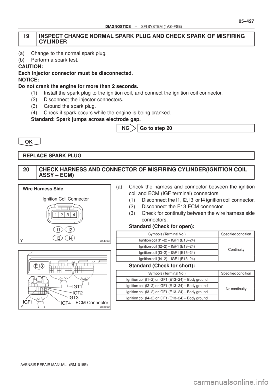
A54393
I1
Wire Harness Side
Ignition Coil Connector
I2
I3I4
A81699
E13
ECM Connector IGF1IGT4
IGT3IGT2 IGT1
± DIAGNOSTICSSFI SYSTEM (1AZ±FSE)
05±427
AVENSIS REPAIR MANUAL (RM1018E)
19 INSPECT CHANGE NORMAL SPARK PLUG AND CHECK SPARK OF MISFIRING
CYLINDER
(a) Change to the normal spark plug.
(b) Perform a spark test.
CAUTION:
Each injector connector must be disconnected.
NOTICE:
Do not crank the engine for more than 2 seconds.
(1) Install the spark plug to the ignition coil, and connect the ignition coil connector.
(2) Disconnect the injector connectors.
(3) Ground the spark plug.
(4) Check if spark occurs while the engine is being cranked.
Standard: Spark jumps across electrode gap.
NG Go to step 20
OK
REPLACE SPARK PLUG
20 CHECK HARNESS AND CONNECTOR OF MISFIRING CYLINDER(IGNITION COIL
ASSY ± ECM)
(a) Check the harness and connector between the ignition
coil and ECM (IGF terminal) connectors
(1) Disconnect the I1, I2, I3 or I4 ignition coil connector.
(2) Disconnect the E13 ECM connector.
(3) Check for continuity between the wire harness side
connectors.
Standard (Check for open):
Symbols (Terminal No.)Specified condition
Ignition coil (I1±2) ± IGF1 (E13±24)
Ignition coil (I2±2) ± IGF1 (E13±24)ContinuityIgnition coil (I3±2) ± IGF1 (E13±24)Continuity
Ignition coil (I4±2) ± IGF1 (E13±24)
Standard (Check for short):
Symbols (Terminal No.)Specified condition
Ignition coil (I1±2) or IGF1 (E13±24) ± Body ground
Ignition coil (I2±2) or IGF1 (E13±24) ± Body groundNo continuityIgnition coil (I3±2) or IGF1 (E13±24) ± Body groundNo continuity
Ignition coil (I4±2) or IGF1 (E13±24) ± Body ground
Page 3942 of 5135
05±428
± DIAGNOSTICSSFI SYSTEM (1AZ±FSE)
AVENSIS REPAIR MANUAL (RM1018E)
(b) Check the harness and connector between the ignition
coil and ECM (IGT terminal) connectors
(1) Disconnect the I1, I2, I3 or I4 ignition coil connector.
(2) Disconnect the E13 ECM connector.
(3) Check for continuity between the wire harness side
connectors.
Standard (Check for open):
Symbols (Terminal No.)Specified condition
Ignition coil (I1±3) ± IGT1 (E13±8)
Ignition coil (I2±3) ± IGT2 (E13±9)ContinuityIgnition coil (I3±3) ± IGT3 (E13±10)Continuity
Ignition coil (I4±3) ± IGT4 (E13±11)
Standard (Check for short):
Symbols (Terminal No.)Specified condition
Ignition coil (I1±3) or IGT1 (E13±8) ± Body ground
Ignition coil (I2±3) or IGT2 (E13±9) ± Body groundNo continuityIgnition coil (I3±3) or IGT3 (E13±10) ± Body groundNo continuity
Ignition coil (I4±3) or IGT4 (E13±11) ± Body ground
NG REPAIR OR REPLACE HARNESS OR
CONNECTOR
OK
REPLACE IGNITION COIL ASSY (THEN CONFIRM THAT THERE IS NO MISFIRE)
Page 3956 of 5135
A81016
ECM
STA
E97
B±Y
IJW±BJ12
B B
J13
J/C W±B 1 5
32 1AM2 2
B
B±R1
S51
S4
Starter
Battery7IK1
FL MAIN 3 3
Engine Room
R/B No. 3
B B 55
55 1
11A
BB±R
IE41
(LHD)IP11
(RHD)B±R
Engine
Room
R/B No. 1
Driver
Side R/B ST
Relay
2
DJ
9
DADriver
Side J/B B±R
B±RI13
Ignition Switch
4
5
AM2 ST2B±Y
B±Y
6
2ST 1
6 Fuse
Block
B±WB±Y B±YB±Y
J12
A C
J13C
J13
± DIAGNOSTICSECD SYSTEM (1CD±FTV)
05±691
AVENSIS REPAIR MANUAL (RM1018E)
STARTER SIGNAL CIRCUIT
CIRCUIT DESCRIPTION
HINT:
While the engine is being cranked, current flows from terminal ST2 of the ignition switch to the ST relay coil
and also current flows to terminal STA of the ECM (STA signal).
WIRING DIAGRAM
05B5Y±02
Page 4000 of 5135
![TOYOTA AVENSIS 2005 Service Repair Manual G24063
SST
SST
± DIAGNOSTICSELECTRONIC CONTROLLED AUTOMATIC
TRANSAXLE [ECT] (U341E)05±993
AVENSIS REPAIR MANUAL (RM1018E)
9. HYDRAULIC TEST
(a) Measure the line pressure.
NOTICE:
�Do the test at n TOYOTA AVENSIS 2005 Service Repair Manual G24063
SST
SST
± DIAGNOSTICSELECTRONIC CONTROLLED AUTOMATIC
TRANSAXLE [ECT] (U341E)05±993
AVENSIS REPAIR MANUAL (RM1018E)
9. HYDRAULIC TEST
(a) Measure the line pressure.
NOTICE:
�Do the test at n](/manual-img/14/57441/w960_57441-3999.png)
G24063
SST
SST
± DIAGNOSTICSELECTRONIC CONTROLLED AUTOMATIC
TRANSAXLE [ECT] (U341E)05±993
AVENSIS REPAIR MANUAL (RM1018E)
9. HYDRAULIC TEST
(a) Measure the line pressure.
NOTICE:
�Do the test at normal operation ATF temperature 50 to 80�C (122 to 176�F).
�The line pressure test should always be carried out in pairs. One technician should observe
the conditions of wheels or wheel stopper outside the vehicle while the other is doing the test.
�Be careful to prevent SST's hose from interfering with the exhaust pipe.
(1) Warm up the ATF.
(2) Remove the test plug on the left side of the trans-
axle case and connect SST.
SST 09992±00095 (09992± 00231, 09992±00271)
(3) Fully apply the parking brake and chock the 4
wheels.
(4) Connect the hand±held tester to DLC3.
(5) Start the engine and check idling speed.
(6) Keep your left foot pressing firmly on the brake ped-
al and shift into D range.
(7) Measure the line pressure when the engine is idling.
(8) Depress the accelerator pedal all the way down.
Quickly read the highest line pressure when engine
speed reaches stall speed.
(9) In the same way, do the test in R range.
Specified line pressure:
ConditionD range kPa (kgf / cm2, psi)R range kPa (kgf / cm2, psi)
Idling370 to 410 (3.8 to 4.2, 54 to 60)540 to 640 (5.5 to 6.5, 78 to 92)
Stall1,110 to 1,230 (11.3 to 12.5, 161 to 178)1,700 to 1,810 (17.3 to 18.5, 246 to 263)
Evaluation:
ProblemPossible cause
If the measured values at all ranges are higher�Shift solenoid valve SLT defective
�Regulator valve detective
If the measured values at all ranges are lower
�Shift solenoid valve SLT defective
�Regulator valve detective
�Oil pump defective
If pressure is low in the D range only�D range circuit fluid leak
�Forward clutch defective
If pressure is low in the R range only
�R range circuit fluid leak
�Reverse clutch defective
�1st and reverse brake defective