Page 3881 of 5135
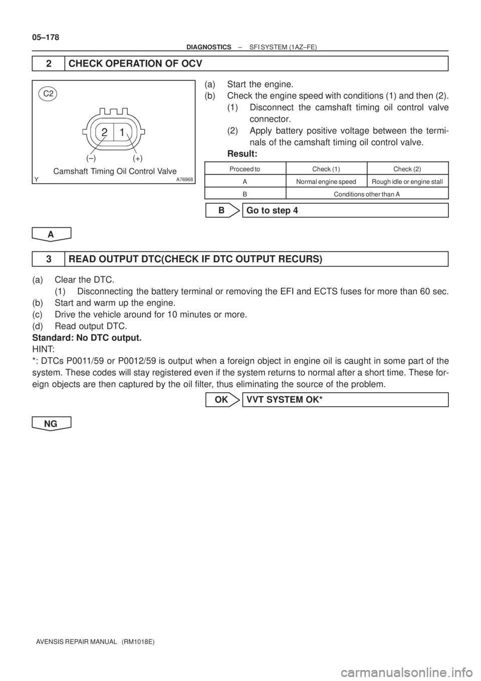
A76968
C2
(±) (+)
Camshaft Timing Oil Control Valve
05±178
± DIAGNOSTICSSFI SYSTEM (1AZ±FE)
AVENSIS REPAIR MANUAL (RM1018E)
2 CHECK OPERATION OF OCV
(a) Start the engine.
(b) Check the engine speed with conditions (1) and then (2).
(1) Disconnect the camshaft timing oil control valve
connector.
(2) Apply battery positive voltage between the termi-
nals of the camshaft timing oil control valve.
Result:
Proceed toCheck (1)Check (2)
ANormal engine speedRough idle or engine stall
BConditions other than A
B Go to step 4
A
3 READ OUTPUT DTC(CHECK IF DTC OUTPUT RECURS)
(a) Clear the DTC.
(1) Disconnecting the battery terminal or removing the EFI and ECTS fuses for more than 60 sec.
(b) Start and warm up the engine.
(c) Drive the vehicle around for 10 minutes or more.
(d) Read output DTC.
Standard: No DTC output.
HINT:
*: DTCs P0011/59 or P0012/59 is output when a foreign object in engine oil is caught in some part of the
system. These codes will stay registered even if the system returns to normal after a short time. These for-
eign objects are then captured by the oil filter, thus eliminating the source of the problem.
OK VVT SYSTEM OK*
NG
Page 3882 of 5135
A79111
OCV Signal Waveform1 msec./Division 5 V/
Division
GND
(A)(A) (A)
E13
OC1 +OC1±
±
DIAGNOSTICS SFI SYSTEM(1AZ±FE)
05±179
AVENSIS REPAIR MANUAL (RM1018E)
4CHECK ECM(OCV SIGNAL)
(a)Inspection using the oscilloscope.
(b)During idling, check the waveform between the terminals
of the E13 ECM connector.
Standard:
Symbols (Terminal No.)Specified condition
OC1+ (E13±15) ± OC1± (E13±14)Correct waveform is as shown
HINT:
The waveform frequency (A) is lengthened as the engine speed
becomes higher.
NGCHECK AND REPLACE ECM (See page 01±32)
OK
5CHECK OIL CONTROL VALVE FILTER
NGREPLACE OIL CONTROL VALVE FILTER
OK
6CHECK CAMSHAFT TIMING OIL CONTROL VALVE ASSY(OCV) (See page 10±20)
OKGo to step 8
NG
7REPLACE CAMSHAFT TIMING OIL CONTROL VALVE ASSY(OCV)
GO
8CHECK CAMSHAFT TIMING GEAR ASSY (See page 14±171)
OK Go to step 10
NG
Page 3883 of 5135
05±180
±
DIAGNOSTICS SFI SYSTEM(1AZ±FE)
AVENSIS REPAIR MANUAL (RM1018E)
9REPLACE CAMSHAFT TIMING GEAR ASSY
GO
10CHECK FOR BLOCKAGE(OCV, OIL CHECK VALVE AND OIL HOLE)
NGREPAIR OR REPLACE
OK
11READ OUTPUT DTC(CHECK IF DTC OUTPUT RECURS)
(a)Clear the DTC. (1)Disconnecting the battery terminal or removing the EFI and ECTS fuses for more than 6\
0 sec.
(b)Start and warm up the engine.
(c)Drive the vehicle around for 10 minutes or more.
(d)Read output DTC.
Standard: No DTC output.
HINT:
*: DTCs P0011/59 or P0012/59 is output when a foreign object in engine oil is caught in some part of \
the
system. These codes will stay registered even if the system returns to normal a\
fter a short time. These for-
eign objects are then captured by the oil filter, thus eliminating the source of the problem.
OKVVT SYSTEM OK*
NG
CHECK AND REPLACE ECM (See page 01±32)
Page 3892 of 5135
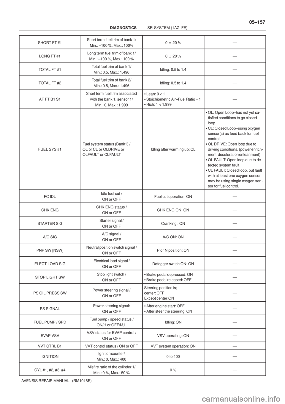
± DIAGNOSTICSSFI SYSTEM (1AZ±FE)
05±157
AVENSIS REPAIR MANUAL (RM1018E)SHORT FT #1
Short term fuel trim of bank 1/
Min.: ±100 %, Max.: 100%0 �20 %�
LONG FT #1Long term fuel trim of bank 1/
Min.: ±100 %, Max.: 100 %0 �20 %�
TOTAL FT #1Total fuel trim of bank 1/
Min.: 0.5, Max.: 1.496Idling: 0.5 to 1.4�
TOTAL FT #2Total fuel trim of bank 2/
Min.: 0.5, Max.: 1.496Idling: 0.5 to 1.4�
AF FT B1 S1
Short term fuel trim associated
with the bank 1, sensor 1/
Min.: 0, Max.: 1.999�Lean: 0 < 1
�Stoichiometric Air±Fuel Ratio = 1
�Rich: 1 < 1.999
�
FUEL SYS #1
Fuel system status (Bank1) /
OL or CL or OLDRIVE or
OLFAULT or CLFAULT
Idling after warming up: CL
�OL: Open Loop±has not yet sa-
tisfied conditions to go closed
loop.
�CL: Closed Loop±using oxygen
sensor(s) as feed back for fuel
control.
�OL DRIVE: Open loop due to
driving conditions. (power enrich-
ment, deceleration enleanment)
�OL FAULT: Open loop due to de-
tected system fault.
�CL FAULT: Closed loop, but fault
with at least one oxygen sensor
may be using single oxygen sen-
sor for fuel control.
FC IDLIdle fuel cut /
ON or OFFFuel cut operation: ON�
CHK ENGCHK ENG status /
ON or OFFCHK ENG ON: ON�
STARTER SIGStarter signal /
ON or OFFCranking: ON�
A/C SIGA/C signal /
ON or OFFA/C ON: ON�
PNP SW [NSW]Neutral position switch signal /
ON or OFFP or N position: ON�
ELECT LOAD SIGElectrical load signal /
ON or OFFDefogger switch ON: ON�
STOP LIGHT SWStop light switch /
ON or OFF�Brake pedal depressed: ON
�Brake pedal released: OFF�
PS OIL PRESS SWPower steering signal /
ON or OFFSteering position is;
center: OFF
Except center:ON
�
PS SIGNALPower steering signal/
ON or OFF�After engine start: OFF
�After steer the steering: ON�
FUEL PUMP / SPDFuel pump / speed status /
ON/H or OFF/M,LIdling: ON�
EVAP VSVVSV status for EVAP control /
ON or OFFVSV operating: ON�
VVT CTRL B1VVT control status / ON or OFFVVT system operation: ON�
IGNITIONIgnition counter/
Min.: 0, Max.: 4000 to 400�
CYL #1, #2, #3, #4Misfire ratio of the cylinder 1/
Min.: 0 %, Max.: 50 %0 %�
Page 3894 of 5135
±
DIAGNOSTICS SFI SYSTEM(1AZ±FE)
05±159
AVENSIS REPAIR MANUAL (RM1018E)
BASIC INSPECTION
When the malfunction is not confirmed in the DTC check, troubleshooting \
should be carried out in all the
possible circuits considered as causes of the problem. In many cases, by carrying out the basic engine check
shown in the following flow chart, the location causing the problem can be found quickly and efficiently.
Therefore, using this check is essential in the engine troubleshooting.
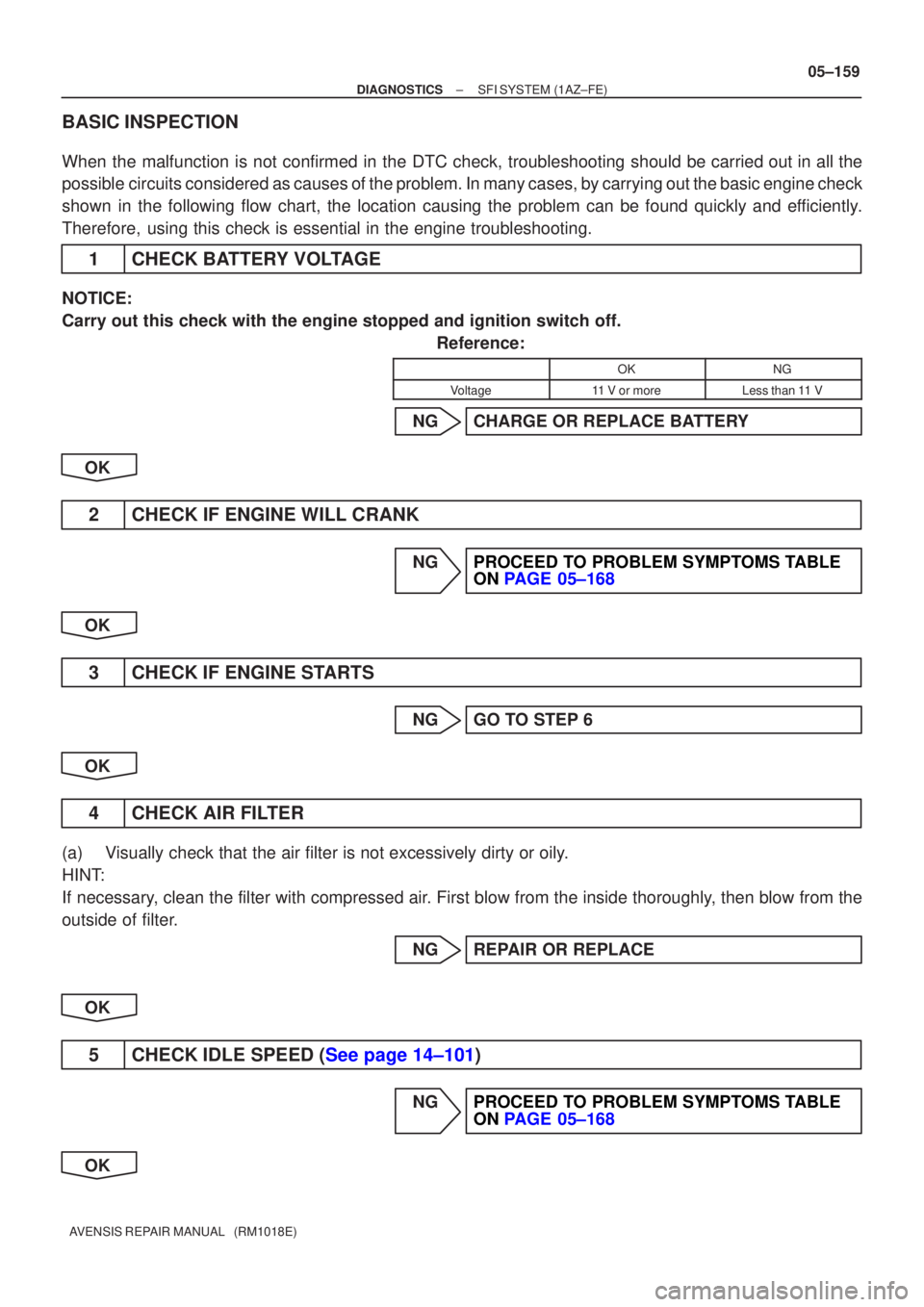
1CHECK BATTERY VOLTAGE
NOTICE:
Carry out this check with the engine stopped and ignition switch off.
Reference:
OKNG
Voltage11 V or moreLess than 11 V
NGCHARGE OR REPLACE BATTERY
OK
2CHECK IF ENGINE WILL CRANK
NGPROCEED TO PROBLEM SYMPTOMS TABLE ON PAGE 05±168
OK
3CHECK IF ENGINE STARTS
NGGO TO STEP 6
OK
4CHECK AIR FILTER
(a)Visually check that the air filter is not excessively dirty or oily.
HINT:
If necessary, clean the filter with compressed air. First blow from the inside thoroughly, then blow from the
outside of filter. NGREPAIR OR REPLACE
OK
5CHECK IDLE SPEED (See page 14±101)
NGPROCEED TO PROBLEM SYMPTOMS TABLE ON PAGE 05±168
OK
Page 3896 of 5135
05±122
±
DIAGNOSTICS SFI SYSTEM(1ZZ±FE/3ZZ±FE)
AVENSIS REPAIR MANUAL (RM1018E)
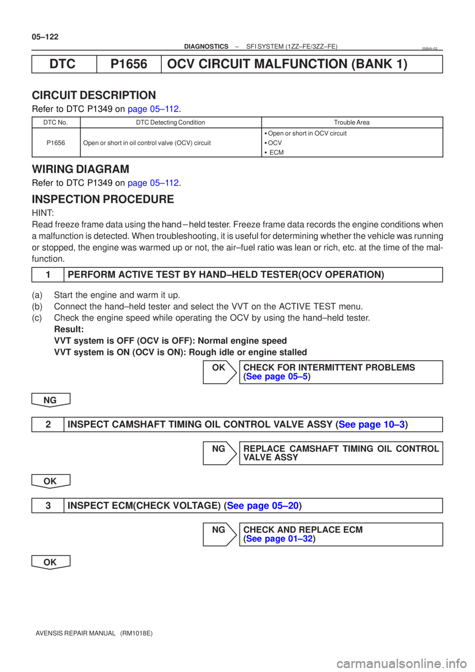
DTCP1656OCV CIRCUIT MALFUNCTION (BANK 1)
CIRCUIT DESCRIPTION
Refer to DTC P1349 on page 05±112.
DTC No.DTC Detecting ConditionTrouble Area
P1656Open or short in oil control valve (OCV) circuit
� Open or short in OCV circuit
� OCV
� ECM
WIRING DIAGRAM
Refer to DTC P1349 on page 05±112.
INSPECTION PROCEDURE
HINT:
Read freeze frame data using \f���� ����\b�\f��\f�
� Freeze frame data records the engine conditions when
a malfunction is detected. When troubleshooting, it is useful for determi\
ning whether the vehicle was running
or stopped, the engine was warmed up or not, the air±fuel ratio was lea\
n or rich, etc. at the time of the mal-
function.
1PERFORM ACTIVE TEST BY HAND±HELD TESTER(OCV OPERATION)
(a)Start the engine and warm it up.
(b)Connect the hand±held tester and select the VVT on the ACTIVE TEST me\
nu.
(c)Check the engine speed while operating the OCV by using the hand±held\
tester. Result:
VVT system is OFF (OCV is OFF): Normal engine speed
VVT system is ON (OCV is ON): Rough idle or engine stalled
OKCHECK FOR INTERMITTENT PROBLEMS(See page 05±5)
NG
2INSPECT CAMSHAFT TIMING OIL CONTROL VALVE ASSY (See page 10±3)
NG REPLACE CAMSHAFT TIMING OIL CONTROL VALVE ASSY
OK
3INSPECT ECM(CHECK VOLTAGE) (See page 05±20)
NG CHECK AND REPLACE ECM (See page 01±32)
OK
05B4A±02
Page 3897 of 5135
A65743OCV+OCV±
E13
ECM Connector
Camshaft Timing Oil Control Valve
Connector
A53155
Wire Harness Side
C2
±
DIAGNOSTICS SFI SYSTEM(1ZZ±FE/3ZZ±FE)
05±123
AVENSIS REPAIR MANUAL (RM1018E)
4CHECK HARNESS AND CONNECTOR(ECM ± OCV)
(a)Disconnect the camshaft timing oil control valve connec-
tor.
(b)Disconnect the E13 ECM connector.
(c)Check for continuity between the wire harness side con- nectors.
Standard (Check for open):
Symbols (Terminal No.)Specified condition
Oil control valve (C2±1) ± OCV+ (E13±14)ContinuityOil control valve (C2±2) ± OCV± (E13±15)Continuity
Standard (Check for short):
Symbols (Terminal No.)Specified condition
Oil control valve (C2±1)or OCV+ (E13±14) ± Body groundNocontinuityOil control valve (C2±2)or OCV± (E13±15) ± Body groundNo continuity
NGREPAIR OR REPLACE HARNESS OR CONNECTOR
OK
CHECK FOR INTERMITTENT PROBLEMS (See page 05±5)
Page 3898 of 5135
A63955
GND
CH1
(G2+)
CH2
(NE+) GND
±
DIAGNOSTICS SFI SYSTEM(1AZ±FE)
05±229
AVENSIS REPAIR MANUAL (RM1018E)
DTCP0340/12CAMSHAFT POSITION SENSOR ºAº
CIRCUIT (BANK 1 OR SINGLE SENSOR)
DTCP0341/12CAMSHAFT POSITION SENSOR ºAº CIRCUIT RANGE/PERFORMANCE (BANK 1
OR SINGLE SENSOR)
CIRCUIT DESCRIPTION
The camshaft position sensor (G signal) consists of a magnet, iron core a\
nd pickup coil.
The G signal rotor has 3 teeth on its outer circumference and is install\
ed on the intake camshaft.
When the camshafts rotate, the protrusion on the signal plate and the air gap on the pickup coil changes,
causing fluctuations in the magnetic field and generating an electromoti\
ve force in the pickup coil.
The NE signal plate (crankshaft position sensor plate) has 34 teeth an\
d is installed to the crankshaft. The
NE signal sensor generates 34 signals at every engine revolution. The EC\
M detects the crankshaft angle
and the engine revolution based on the NE signals, and the cylinder and the\
angle of the VVT based on the
combination of the G and NE signals.
DTC No.DTC Detection ConditionTrouble Area
P0340/12
�No camshaft position sensor signal to ECM during cranking
(1 trip detection logic)�Open or short in camshaft position sensor circuit
ChftitiP0340/12(1 tri detection logic)
�No camshaft position sensor signal to ECM with engine
speed 600 rpm or more (1 trip detection logic)�Camshaft position sensor
� Camshaft timing pulley
�Timingchainhasjumpedatooth
P0341/12While crankshaft rotates twice, camshaft position sensor signal
is input to ECM 12 times or more (1 trip detection logic)�Timing chain has jumped a tooth
�ECM
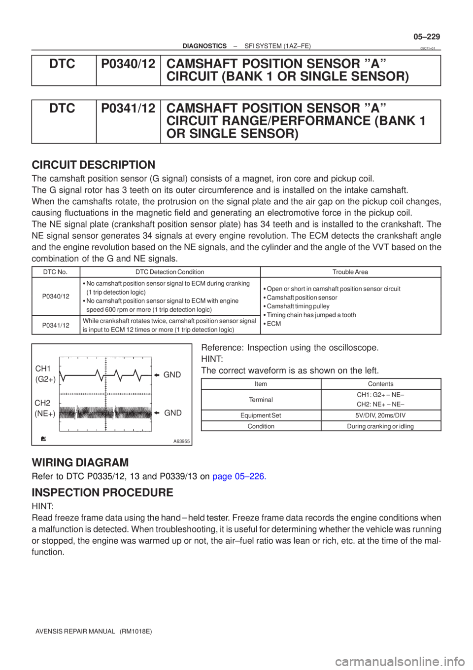
Reference: Inspection using the oscilloscope.
HINT:
The correct waveform is as shown on the left.
ItemContents
TerminalCH1: G2+ ± NE±
CH2: NE+ ± NE±
Equipment Set5V/DIV, 20ms/DIV
ConditionDuring cranking or idling
WIRING DIAGRAM
Refer to DTC P0335/12, 13 and P0339/13 on page 05±226.
INSPECTION PROCEDURE
HINT:
Read freeze frame data using \f�� �� ����\b� \f��\f�
� Freeze frame data records the engine conditions when
a malfunction is detected. When troubleshooting, it is useful for determi\
ning whether the vehicle was running
or stopped, the engine was warmed up or not, the air±fuel ratio was lea\
n or rich, etc. at the time of the mal-
function.
05C71±01