Page 4440 of 5135
A81008
ECM
E1017
V−W C11
Combination
Meter Assy
(RHD) V−W 18
J20HJ/C
SPD
(RHD)J20H
(LHD)J10H
(LHD)J10H
− DIAGNOSTICSECD SYSTEM (1CD−FTV)(From September, 2003)
05−409
AVENSIS Supplement (RM1045E)
WIRING DIAGRAM
INSPECTION PROCEDURE
HINT:
Read freeze frame data usingthe hand−held tester.Freeze frame data records the engine conditions when
a malfunction is detected. When troubleshooting, freeze frame data can help determine if the vehicle was
running or stopped, if the engine was warmed up or not, if the air−fuel ratio was lean or rich, and other data
from the time the malfunction occurred.
1CHECK OPERATION OF SPEEDOMETER
(a) Drive the vehicle and check if the operation of the speedometer in the combination meter is normal.
HINT:
The vehicle speed sensor is operating normally if the speedometer display is normal.
NG CHECK SPEEDOMETER CIRCUIT (INCLUDE
SPEED SENSOR)
OK
Page 4444 of 5135
A91213
MREL B−W
GR8
3 EFI MAIN Relay
W−BE9 E12
2 EE1
EFIB−R
(LHD) 1
B5
Battery FL MAINI17
Intake Shutter (Throttle Valve)
LUSL 4
1
1
1 1A 1 1
121
2
B−W 10Engine Room R/B No.1ECM
1
Engine Room
R/B No. 3 3
3 B
EC B−Y
(RHD) IE1 2G−R
3
EI GR W−B DUTY
GND +B
− DIAGNOSTICSECD SYSTEM (1CD−FTV)(From September, 2003)
05−405
AVENSIS Supplement (RM1045E)
WIRING DIAGRAM
INSPECTION PROCEDURE
HINT:
SRead freeze frame data usingthe hand−held tester.Freeze frame data records the engine conditions
when a malfunction is detected. When troubleshooting, freeze frame data can help determine if the
vehicle was running or stopped, if the engine was warmed up or not, if the air−fuel ratio was lean or
rich, and other data from the time the malfunction occurred.
SAfter engine warm−up, DTC P0488 malfunction is set1second or more passed after quickly accelerat-
ing the engine from idling.
Page 4448 of 5135

A12544
VCECM
EGLS
E2
R
R
−W
BR
E18
EGR Valve Position Sensor
1
3
2 18
E13
33
E12
28
E13
VC
E2
EGLS 5V
E1
A85350
E18
Front View
Wire Harness Side:
EGR valve position Sensor Connector
12 3
VC E2 EGLS
05 −400
−
DIAGNOSTICS ECD SYSTEM (1CD−FTV)(From September, 2003)
AVENSIS Supplement (RM1045E)
WIRING DIAGRAM
INSPECTION PROCEDURE
HINT:
Read freeze frame data using the hand−held tester. Freeze frame data records the engine conditions when
a malfunction is detected. When troubleshooting, freeze frame data can help determine if the vehicle was
running or stopped, if the engine was warmed up or not, if the air −fuel ratio was lean or rich, and other data
from the time the malfunction occurred.
1 CHECK HARNESS AND CONNECTOR(EGR VALVE POSITION SENSOR VOLTAGE)
(a) Disconnect the E18 EGR valve position sensor connec-
tor.
(b) Measure the voltage between the specified terminals of
the E18 EGR valve position sensor connector.
Standard:
Tester ConnectionSpecified Condition
VC (E18 −1) − E2 (E18 −2)4.5 to 5.5 V
(c) Reconnect the EGR valve position sensor connector.
NG Go to step 4
OK
2 INSPECT EGR VALVE POSITION SENSOR(RESISTANCE) (See page 12− 9)
NG REPLACE EGR VALVE POSITION SENSOR
(See page 14−1 08)
OK
Page 4453 of 5135
 1
B5
Battery FL MAINE17
EGR Valve
EGRS 3
1
1
1
1A 1 1
121 2R−L
B−W 10GR
Engine Room R/B No.1ECM
2
1
Engine Room
R/B No.")
A91220
MREL B−W
GR8
3 EFI MAIN Relay
W−BE9 E12
2 IE1
EE1
EFIB−R
(LHD) 1
B5
Battery FL MAINE17
EGR Valve
EGRS 3
1
1
1
1A 1 1
121 2R−L
B−W 10GR
Engine Room R/B No.1ECM
2
1
Engine Room
R/B No. 3 3
3 B
EC B−Y
(RHD)
− DIAGNOSTICSECD SYSTEM (1CD−FTV)(From September, 2003)
05−395
AVENSIS Supplement (RM1045E)
WIRING DIAGRAM
INSPECTION PROCEDURE
HINT:
SRead freeze frame data usingthe hand−held tester.Freeze frame data records the engine conditions
when a malfunction is detected. When troubleshooting, freeze frame data can help determine if the
vehicle was running or stopped, if the engine was warmed up or not, if the air−fuel ratio was lean or
rich, and other data from the time the malfunction occurred.
SAfter engine warm−up, DTC P0400 malfunction is set1second or more passed after quickly accelerat-
ing the engine from idling.
1CHECK OTHER DTC OUTPUT(IN ADDITION TO P0400)
(a) Connect the hand−held tester to the DLC3.
(b) Turn the ignition switch to ON and turn the hand−held tester ON.
(c) Select the item ”DIAGNOSIS / OBD/MOBD / DTC INFO / CURRENT CODES”.
(d) Read DTCs.
Result:
Display (DTC output)Proceed
P0400A
P0400 and P0405 and/or P0406B
HINT:
If any other codes besides P0400 are output, perform troubleshooting for those DTCs first.
Page 4457 of 5135
Glow Plug ECMGlow
Plug
Relay Battery
Duty Ratio
A81018
Ignition Switch
Glow Plug
Engine Speed
Starting EngineAfter Glow Time OFFOFF ON ON
OFF After Glow System:
0
020
(68)")
A81017
Generator (Alternator)Glow Plug ECMGlow
Plug
Relay Battery
Duty Ratio
A81018
Ignition Switch
Glow Plug
Engine Speed
Starting EngineAfter Glow Time OFFOFF ON ON
OFF After Glow System:
0
020
(68)40
(104)
After Glow Time (second)Engine Coolant Temperature_C(_F) 120 05−386
− DIAGNOSTICSECD SYSTEM (1CD−FTV)(From September, 2003)
AVENSIS Supplement (RM1045E)
DTC P0380 GLOW PLUG/HEATER CIRCUIT ”A”
CIRCUIT DESCRIPTION
The glow plug is mounted inside the engine combustion chamber. To ensure the efficient engine starting with
a cold engine, the ECM calculates a time interval of the current needs to flow through the glow plug depend-
ing on the starting engine coolant temperature when the ignition switch is turned to ON. The ECM then turns
on the glow plug relay and permits the current to flow through the glow plug based on the ECM’s calculated
time. The glow plug is then heated and enhances fuel combustion with a cold engine.
This DTC will be set if there is open in glow plug itself or its circuit.
HINT:
After the engine is started, the ECM performs an ”after−glow” for a certain period of time. In proportion to
the actual engine coolant temperature, the time period varies. The after−grow reduces diesel engine knock-
ing, white smoke and engine noises with a cold engine.
05CPT−03
Page 4460 of 5135
(From September, 2003)
05 −389
AVENSIS Supplement (RM1045E)
INSPEC")
A81506
From Battery
Glow System Wiring Diagram:
Glow Plug Relay
Glow Plug ECM
GREL
GLOW Fuse
−
DIAGNOSTICS ECD SYSTEM (1CD−FTV)(From September, 2003)
05 −389
AVENSIS Supplement (RM1045E)
INSPECTION PROCEDURE
HINT:
S After completing repairs, confirm that P0380 is not present again.
S Read freeze frame data using the hand −held tester. Freeze frame data records the engine conditions
when a malfunction is detected. When troubleshooting, freeze frame data can help determine if the
vehicle was running or stopped, if the engine was warmed up or not, if the air −fuel ratio was lean or
rich, and other data from the time the malfunction occurred.
1 CHECK OTHER DTC OUTPUT(IN ADDITION TO DTC P0380)
(a) Connect the hand −held tester to the DLC3.
(b) Turn the ignition switch to ON and turn the hand −held tester ON.
(c) Select the item ”DIAGNOSIS / OBD/MOBD / DTC INFO / CURRENT CODES”.
(d) Read DTCs.
Result:
Display (DTC output)Proceed to
P0380A
P0380 and P0622B
HINT:
If any other codes besides P0380 and P0622 are output, perform troubleshooting for those DTCs first.
B GO TO RELEVANT DTC CHART(See page 05 −299)
A
Page 4461 of 5135
(From September, 2003)
AVENSIS Supplement (RM1045E)
2 INSPECT GLOW PLUG RELAY")
A85520
123
2 3
4
4
1
A80987
R/B No. 3:
GLOW
Fuse
B08263
Ohmmeter
Continuity 05−390
− DIAGNOSTICSECD SYSTEM (1CD−FTV)(From September, 2003)
AVENSIS Supplement (RM1045E)
2 INSPECT GLOW PLUG RELAY ASSY
(a) Remove the glow plug relay.
(b) Check for continuity in the glow plug relay.
(1) Check that there is continuity between the termi-
nals.
Standard:
Tester ConnectionSpecified Condition
No continuity
3−4Continuity
(Apply battery voltage to terminals 1 and 2)
1−2Continuity
(c) Reinstall the glow plug relay.
NG REPLACE GLOW PLUG RELAY ASSY
OK
3 INSPECT FUSE(GLOW FUSE)
(a) Remove the GLOW fuse from the R/B No. 3.
(b) Check for continuity in the GLOW fuse.
Standard: Continuity
(c) Reinstall the GLOW fuse.
NG CHECK FOR SHORT IN ALL HARNESS AND
COMPONENTS CONNECTED TO FUSE
OK
4 INSPECT GLOW PLUG ASSY
(a) Disconnect the glow plug wire.
(b) Measure the resistance in the glow plug.
Standard:
Tester ConnectionSpecified Condition
Glow plug terminal−Body groundApproximately 1.1�at 20_C (68_F)
NOTICE:
SExercise extreme care not to damage the glow plug
pipes. Damaging them could cause an open circuit, or
shorten the life of the glow plugs.
SKeep the glow plug free of oil and fuel while cleaning.
SWipe any oil off the terminal and Bakelite washer with
a clean−dry cloth during inspection.
SDo not apply more than11V to the glow plug as it
could cause an open circuit.
(c) Reconnect the glow plug wire.
Page 4464 of 5135
100LY−01
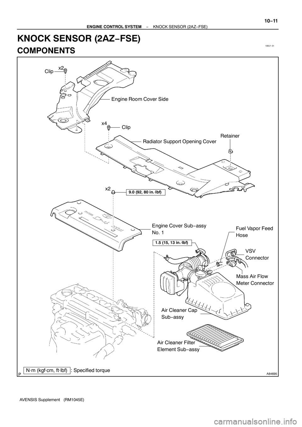
A84695
Mass Air Flow
Meter Connector
N·m (kgf·cm, ft·lbf) : Specified torqueEngine Cover Sub−assy
No. 1
9.0 (92, 80 in.�lbf)
VSV
Connector Fuel Vapor Feed
Hose
Clip
Engine Room Cover Side
Radiator Support Opening Cover
Clip
Retainer
x2
x4
1.5 (15, 13 in.�lbf)
Air Cleaner Filter
Element Sub−assy x2
Air Cleaner Cap
Sub−assy
− ENGINE CONTROL SYSTEMKNOCK SENSOR (2AZ−FSE)
10−11
AVENSIS Supplement (RM1045E)
KNOCK SENSOR (2AZ−FSE)
COMPONENTS
 V−W 18
J20HJ/C
SPD
(RHD)J20H
(LHD)J10H
(LHD)J10H
− DIAGNOSTICSECD SYSTEM (1CD−FTV)(From September, 2003)
05−409
AVENSIS Supplement (RM10")
 1
B5
Battery FL MAINI17
Intake Shutter (Throttle Valve)
LUSL 4
1
1
1 1A 1 1
121
2
B−W 10Engine Room R/B No.1ECM
1
Engine Room")