2005 TOYOTA AVENSIS fuel
[x] Cancel search: fuelPage 5008 of 5135
![TOYOTA AVENSIS 2005 Service Repair Manual 05KAK–01
– DIAGNOSTICSELECTRONIC CONTROLLED AUTOMATIC
TRANSAXLE [ECT] (U341E) (From February, 2004)05–209
AVENSIS REPAIR MANUAL SUPPLEMENT
(RM1098E)
PART AND SYSTEM NAME LIST
This reference list TOYOTA AVENSIS 2005 Service Repair Manual 05KAK–01
– DIAGNOSTICSELECTRONIC CONTROLLED AUTOMATIC
TRANSAXLE [ECT] (U341E) (From February, 2004)05–209
AVENSIS REPAIR MANUAL SUPPLEMENT
(RM1098E)
PART AND SYSTEM NAME LIST
This reference list](/manual-img/14/57441/w960_57441-5007.png)
05KAK–01
– DIAGNOSTICSELECTRONIC CONTROLLED AUTOMATIC
TRANSAXLE [ECT] (U341E) (From February, 2004)05–209
AVENSIS REPAIR MANUAL SUPPLEMENT
(RM1098E)
PART AND SYSTEM NAME LIST
This reference list indicates the part names used in this manual along with their definitions.
Part and system nameDefinition
Toyota HCAC system, Hydrocarbon adsorptive Catalyst
(HCAC) system, HC adsorptive three–way catalystHC adsorptive three–way catalytic converter
Variable Valve Timing sensor, VVT sensorCamshaft position sensor
Variable valve timing system, VVT systemCamshaft timing control system
Camshaft timing oil control valve, Oil control valve OCV,
VVT, VSVCamshaft timing oil control valve
Variable timing and lift, VVTLCamshaft timing and lift control
Crankshaft position sensor ”A”Crankshaft position sensor
Engine speed sensorCrankshaft position sensor
THAIntake air temperature
Knock control moduleEngine knock control module
Knock sensorEngine knock sensor
Mass or volume air flow circuitMass air flow sensor circuit
Vacuum sensorManifold air pressure sensor
Internal control module, Control module, Engine control
ECU, PCMPower train control module
FC idleDeceleration fuel cut
Idle air control valveIdle speed control
VSV for CCV, Canister close valve VSV for canister controlEvaporative emissions canister vent valve
VSV for EVAP, Vacuum switching valve assembly No. 1,
EVAP VAV, Purge VSVEvaporative emissions canister purge valve
VSV for pressure switching valve, Bypass VSVEvaporative emission pressure switching valve
Vapor pressure sensor, EVAP pressure sensor, Evaporative
emission control system pressure sensorFuel tank pressure sensor
Charcoal canisterEvaporative emissions canister
ORVR systemOn–boad refueling vapor recovery system
Intake manifold runner controlIntake manifold tuning system
Intake manifold runner valve, IMRV, IACV (runner valve)Intake manifold tuning valve
Intake control VSVIntake manifold tuning solenoid valve
AFSAir fuel ratio sensor
O2 sensorHeater oxygen sensor
Oxygen sensor pumping current circuitOxygen sensor output signal
Oxygen sensor reference ground circuitOxygen sensor signal ground
Accel position sensorAccelerator pedal position sensor
Throttle actuator control motor, Actuator control motor, Elec-
tronic throttle motor, Throttle control motorElectronic throttle actuator
Electronic throttle control system, Throttle actuator control
systemElectronic throttle control system
Throttle/pedal position sensor, Throttle/pedal position switch,
Throttle position sensor/switchThrottle position sensor
Turbo press sensorTurbocharger pressure sensor
Turbo VSVTurbocharger pressure control solenoid valve
P/S pressure switchPower–steering pressure switch
VSV for ACMActive control engine mount
Speed sensor, Vehicle speed sensor ”A”, Speed sensor for
skid control ECUVehicle speed sensor
ATF temperature sensor, Trans. fluid temp. sensor, ATF
temperature sensor ”A”Transmission fluid temperature sensor
Electronic controlled automatic transmission, ECTElectronically controlled automatic
Intermediate shaft speed sensor ”A”Couter gear speed sensor
Page 5051 of 5135
141UL–01
A93669
A60622
14–32–
ENGINE MECHANICAL CYLINDER HEAD GASKET (1ZZ–FE/3ZZ–FE)(From
February, 2004)
AVENSIS REPAIR MANUAL SUPPLEMENT
(RM1098E)
REPLACEMENT
1. DISCHARGE FUEL SYSTEM PRESSURE (See Pub. No. RM1018E on page 11–1)
2. REMOVE RADIATOR SUPPORT OPENING COVER (See page 14–9)
3. REMOVE ENGINE ROOM COVER SIDE (See page 14–9)
4. REMOVE FRONT WHEEL RH
5. REMOVE ENGINE UNDER COVER SUB–ASSY NO.1 (See page 14–9)
6. REMOVE ENGINE UNDER COVER RH (See page 14–9)
7. DRAIN ENGINE COOLANT (See page 16–5)
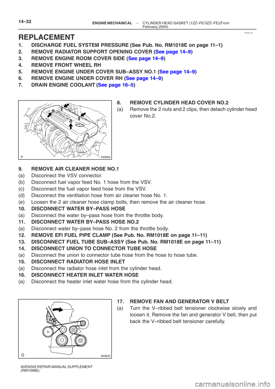
8. REMOVE CYLINDER HEAD COVER NO.2
(a) Remove the 2 nuts and 2 clips, then detach cylinder headcover No.2.
9. REMOVE AIR CLEANER HOSE NO.1
(a) Disconnect the VSV connector.
(b) Disconnect fuel vapor feed No. 1 hose from the VSV.
(c) Disconnect the fuel vapor feed hose from the VSV.
(d) Disconnect the ventilation hose from air cleaner hose No. 1.
(e) Loosen the 2 air cleaner hose clamp bolts, then remove the air cleaner h\
ose.
10. DISCONNECT WATER BY–PASS HOSE
(a) Disconnect the water by–pass hose from the throttle body.
11. DISCONNECT WATER BY–PASS HOSE NO.2
(a) Disconnect water by–pass hose No. 2 from the throttle body.
12. REMOVE EFI FUEL PIPE CLAMP (See Pub. No. RM1018E on page 11–11)
13. DISCONNECT FUEL TUBE SUB–ASSY (See Pub. No. RM1018E on page 11–11)
14. DISCONNECT UNION TO CONNECTOR TUBE HOSE
(a) Disconnect the union to connector tube hose from the hose to hose tube.
15. DISCONNECT RADIATOR HOSE INLET
(a) Disconnect the radiator hose inlet from the cylinder head.
16. DISCONNECT HEATER INLET WATER HOSE
(a) Disconnect the heater inlet water hose from the cylinder head. 17. REMOVE FAN AND GENERATOR V BELT
(a) Turn the V–ribbed belt tensioner clockwise slowly andloosen it. Remove the fan and generator V belt, then put
back the V–ribbed belt tensioner carefully.
Page 5066 of 5135
141UK–01
A784575 Claws
A78458
A78505
A78515
– ENGINE MECHANICALPARTIAL ENGINE ASSY (1ZZ–FE/3ZZ–FE)(From
February, 2004)14–9
AVENSIS REPAIR MANUAL SUPPLEMENT
(RM1098E)
REPLACEMENT
1. DISCHARGE FUEL SYSTEM PRESSURE (See Pub. No. RM1018E on page 11–1)
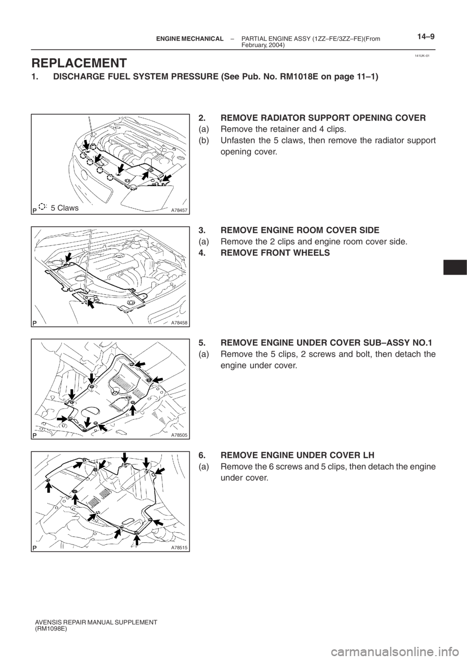
2. REMOVE RADIATOR SUPPORT OPENING COVER
(a) Remove the retainer and 4 clips.
(b) Unfasten the 5 claws, then remove the radiator support
opening cover.
3. REMOVE ENGINE ROOM COVER SIDE
(a) Remove the 2 clips and engine room cover side.
4. REMOVE FRONT WHEELS
5. REMOVE ENGINE UNDER COVER SUB–ASSY NO.1
(a) Remove the 5 clips, 2 screws and bolt, then detach the
engine under cover.
6. REMOVE ENGINE UNDER COVER LH
(a) Remove the 6 screws and 5 clips, then detach the engine
under cover.
Page 5068 of 5135
A76724
A76714
A77338
– ENGINE MECHANICALPARTIAL ENGINE ASSY (1ZZ–FE/3ZZ–FE)(From
February, 2004)14–11
AVENSIS REPAIR MANUAL SUPPLEMENT
(RM1098E)
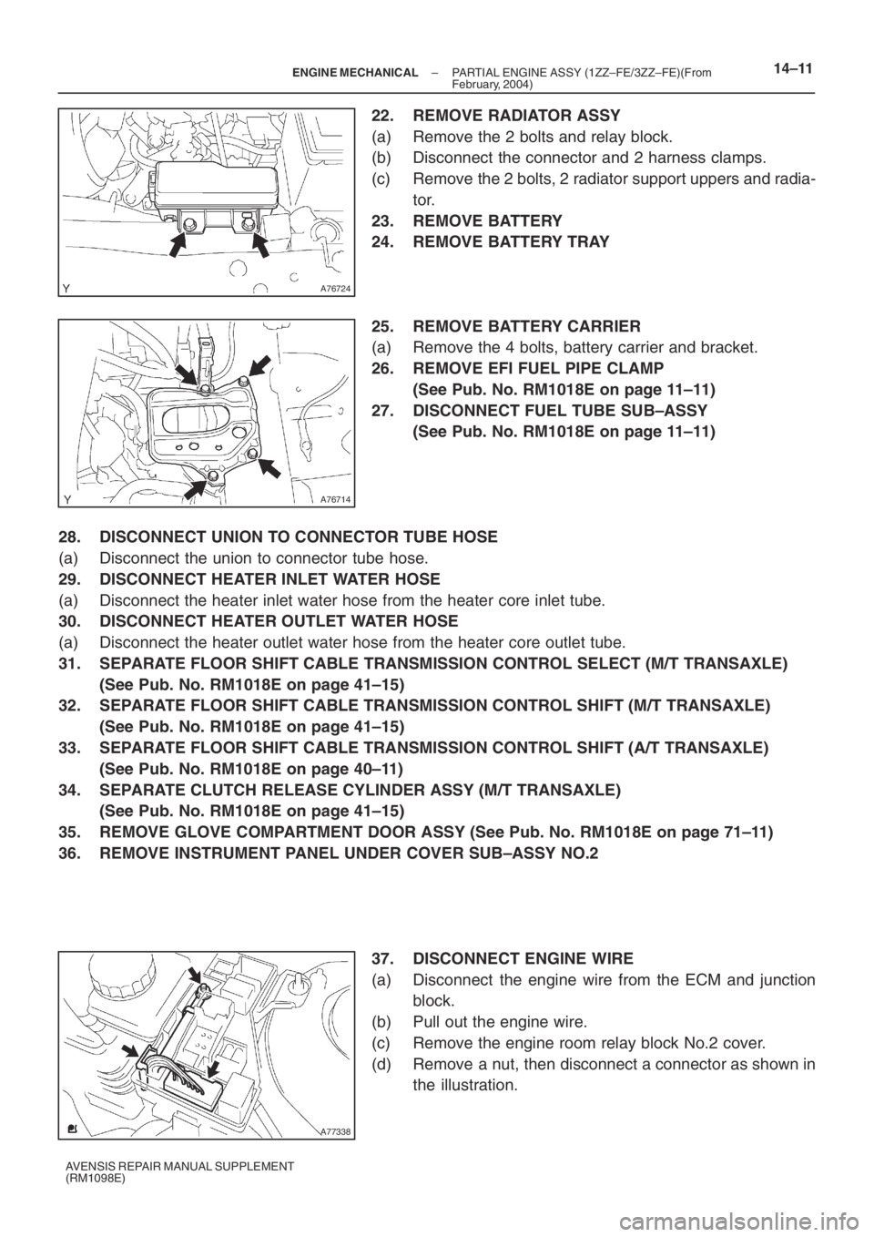
22. REMOVE RADIATOR ASSY
(a) Remove the 2 bolts and relay block.
(b) Disconnect the connector and 2 harness clamps.
(c) Remove the 2 bolts, 2 radiator support uppers and radia-
tor.
23. REMOVE BATTERY
24. REMOVE BATTERY TRAY
25. REMOVE BATTERY CARRIER
(a) Remove the 4 bolts, battery carrier and bracket.
26. REMOVE EFI FUEL PIPE CLAMP
(See Pub. No. RM1018E on page 11–11)
27. DISCONNECT FUEL TUBE SUB–ASSY
(See Pub. No. RM1018E on page 11–11)
28. DISCONNECT UNION TO CONNECTOR TUBE HOSE
(a) Disconnect the union to connector tube hose.
29. DISCONNECT HEATER INLET WATER HOSE
(a) Disconnect the heater inlet water hose from the heater core inlet tube.
30. DISCONNECT HEATER OUTLET WATER HOSE
(a) Disconnect the heater outlet water hose from the heater core outlet tube.
31. SEPARATE FLOOR SHIFT CABLE TRANSMISSION CONTROL SELECT (M/T TRANSAXLE)
(See Pub. No. RM1018E on page 41–15)
32. SEPARATE FLOOR SHIFT CABLE TRANSMISSION CONTROL SHIFT (M/T TRANSAXLE)
(See Pub. No. RM1018E on page 41–15)
33. SEPARATE FLOOR SHIFT CABLE TRANSMISSION CONTROL SHIFT (A/T TRANSAXLE)
(See Pub. No. RM1018E on page 40–11)
34. SEPARATE CLUTCH RELEASE CYLINDER ASSY (M/T TRANSAXLE)
(See Pub. No. RM1018E on page 41–15)
35. REMOVE GLOVE COMPARTMENT DOOR ASSY (See Pub. No. RM1018E on page 71–11)
36. REMOVE INSTRUMENT PANEL UNDER COVER SUB–ASSY NO.2
37. DISCONNECT ENGINE WIRE
(a) Disconnect the engine wire from the ECM and junction
block.
(b) Pull out the engine wire.
(c) Remove the engine room relay block No.2 cover.
(d) Remove a nut, then disconnect a connector as shown in
the illustration.
Page 5073 of 5135
A64023
A93668
A64026
A96570
14–16– ENGINE MECHANICALPARTIAL ENGINE ASSY (1ZZ–FE/3ZZ–FE)(From
February, 2004)
AVENSIS REPAIR MANUAL SUPPLEMENT
(RM1098E)
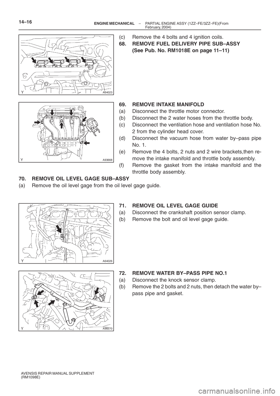
(c) Remove the 4 bolts and 4 ignition coils.
68. REMOVE FUEL DELIVERY PIPE SUB–ASSY
(See Pub. No. RM1018E on page 11–11)
69. REMOVE INTAKE MANIFOLD
(a) Disconnect the throttle motor connector.
(b) Disconnect the 2 water hoses from the throttle body.
(c) Disconnect the ventilation hose and ventilation hose No.
2 from the cylinder head cover.
(d) Disconnect the vacuum hose from water by–pass pipe
No. 1.
(e) Remove the 4 bolts, 2 nuts and 2 wire brackets,then re-
move the intake manifold and throttle body assembly.
(f) Remove the gasket from the intake manifold and the
throttle body assembly.
70. REMOVE OIL LEVEL GAGE SUB–ASSY
(a) Remove the oil level gage from the oil level gage guide.
71. REMOVE OIL LEVEL GAGE GUIDE
(a) Disconnect the crankshaft position sensor clamp.
(b) Remove the bolt and oil level gage guide.
72. REMOVE WATER BY–PASS PIPE NO.1
(a) Disconnect the knock sensor clamp.
(b) Remove the 2 bolts and 2 nuts, then detach the water by–
pass pipe and gasket.
Page 5079 of 5135
A96570
A64026
A93668
A64023
A76713
14–22– ENGINE MECHANICALPARTIAL ENGINE ASSY (1ZZ–FE/3ZZ–FE)(From
February, 2004)
AVENSIS REPAIR MANUAL SUPPLEMENT
(RM1098E)
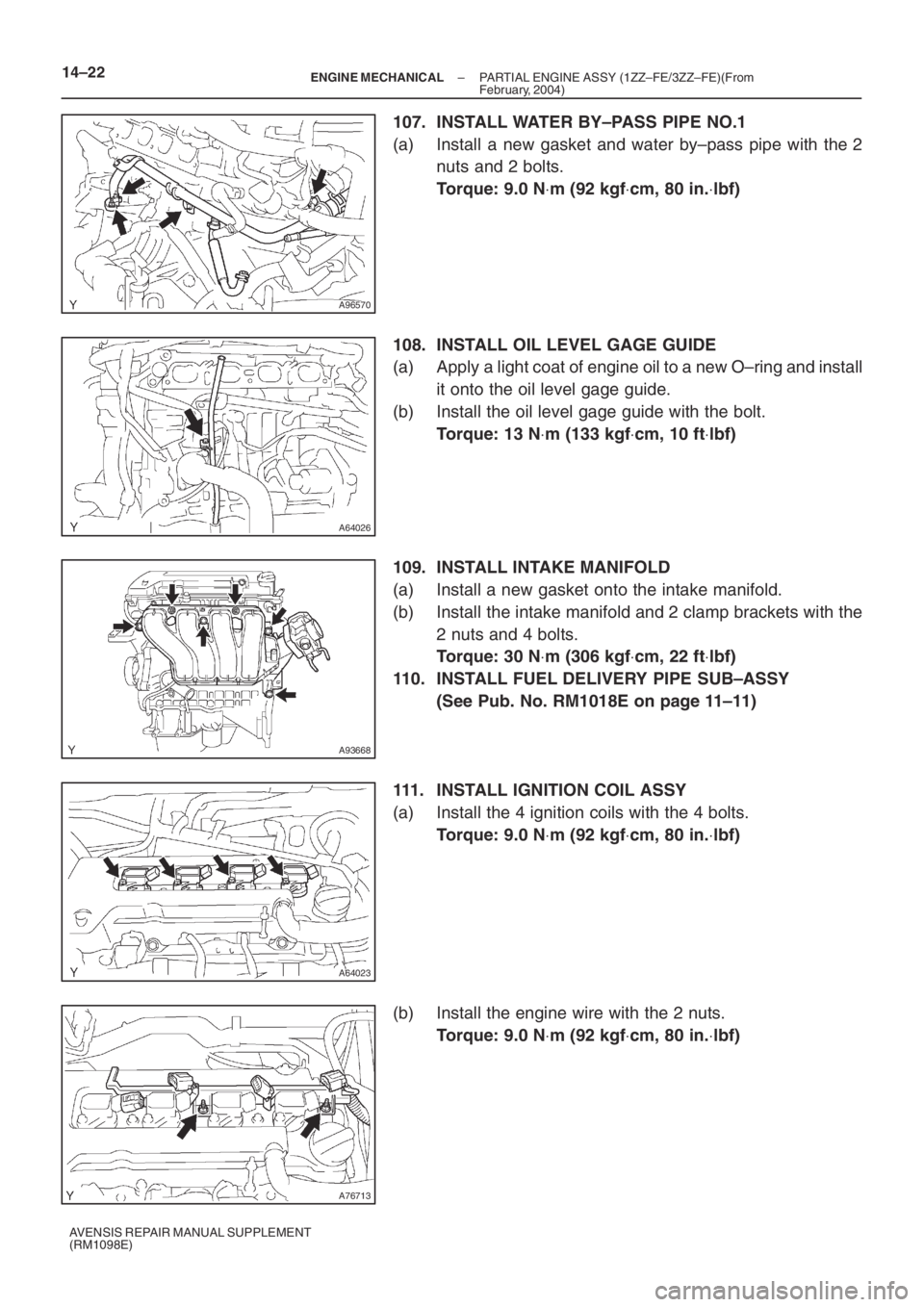
107. INSTALL WATER BY–PASS PIPE NO.1
(a) Install a new gasket and water by–pass pipe with the 2
nuts and 2 bolts.
Torque: 9.0 N⋅m (92 kgf⋅cm, 80 in.⋅lbf)
108. INSTALL OIL LEVEL GAGE GUIDE
(a) Apply a light coat of engine oil to a new O–ring and install
it onto the oil level gage guide.
(b) Install the oil level gage guide with the bolt.
Torque: 13 N⋅m (133 kgf⋅cm, 10 ft⋅lbf)
109. INSTALL INTAKE MANIFOLD
(a) Install a new gasket onto the intake manifold.
(b) Install the intake manifold and 2 clamp brackets with the
2 nuts and 4 bolts.
Torque: 30 N⋅m (306 kgf⋅cm, 22 ft⋅lbf)
110. INSTALL FUEL DELIVERY PIPE SUB–ASSY
(See Pub. No. RM1018E on page 11–11)
111. INSTALL IGNITION COIL ASSY
(a) Install the 4 ignition coils with the 4 bolts.
Torque: 9.0 N⋅m (92 kgf⋅cm, 80 in.⋅lbf)
(b) Install the engine wire with the 2 nuts.
Torque: 9.0 N⋅m (92 kgf⋅cm, 80 in.⋅lbf)
Page 5083 of 5135
A93669
14–26–
ENGINE MECHANICAL PARTIAL ENGINE ASSY (1ZZ–FE/3ZZ–FE)(From
February, 2004)
AVENSIS REPAIR MANUAL SUPPLEMENT
(RM1098E)
137. INSTALL BATTERY
Torque:
5.0 N ⋅m (51 kgf ⋅cm, 44 in. ⋅lbf) for bolt
3.5 N ⋅m (36 kgf ⋅cm, 31 in. ⋅lbf) for nut
138. INSTALL RADIATOR SUPPORT NO.1
(a) Install the 2 radiator supports with the 2 bolts.
Torque: 19 N ⋅m (194 kgf ⋅cm, 14 ft ⋅lbf)
139. INSTALL AIR CLEANER CASE SUB–ASSY
(a) Install the air cleaner case with the 3 bolts.
Torque: 5.0 N ⋅m (51 kgf ⋅cm, 44 in. ⋅lbf)
140. INSTALL AIR CLEANER ASSEMBLY WITH HOSE (See page 10–6)
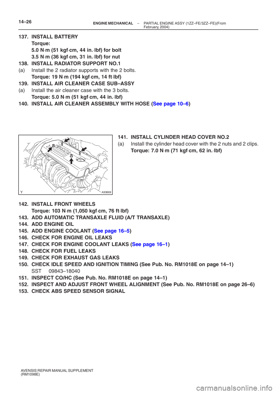
141. INSTALL CYLINDER HEAD COVER NO.2
(a) Install the cylinder head cover with the 2 nuts and 2 clips.
Torque: 7.0 N ⋅m (71 kgf ⋅cm, 62 in. ⋅lbf)
142. INSTALL FRONT WHEELS
Torque: 103 N ⋅m (1,050 kgf ⋅cm, 76 ft ⋅lbf)
143. ADD AUTOMATIC TRANSAXLE FLUID (A/T TRANSAXLE)
144. ADD ENGINE OIL
145. ADD ENGINE COOLANT (See page 16–5)
146. CHECK FOR ENGINE OIL LEAKS
147. CHECK FOR ENGINE COOLANT LEAKS (See page 16–1)
148. CHECK FOR FUEL LEAKS
149. CHECK FOR EXHAUST GAS LEAKS
150. CHECK IDLE SPEED AND IGNITION TIMING (See Pub. No. RM1018E on page 14–1)
SST 09843–18040
151. INSPECT CO/HC (See Pub. No. RM1018E on page 14–1)
152. INSPECT AND ADJUST FRONT WHEEL ALIGNMENT (See Pub. No. RM1018E on page \
26–6)
153. CHECK ABS SPEED SENSOR SIGNAL
Page 5085 of 5135
100P2–01
A95568
Clip
Engine Room Cover Side
Radiator Support Opening Cover
Retainer
Clip
Cylinder Head Cover No. 2
Ventilation Hose No. 1Fuel Vapor Feed Hose No. 1
VSV
Connector
Mass Air Flow
Meter Connector
Fuel Vapor Feed
Hose No. 3
N·m (kgf·cm, ft·lbf)
: Specified torque
x2
7.0 (71, 62 in.⋅lbf)
1.5 (15, 13 in.⋅lbf)
Clip
x4 10–4
– ENGINE CONTROL SYSTEMTHROTTLE BODY ASSY (1ZZ–FE/3ZZ–FE)(From
February, 2004)
AVENSIS REPAIR MANUAL SUPPLEMENT
(RM1098E)
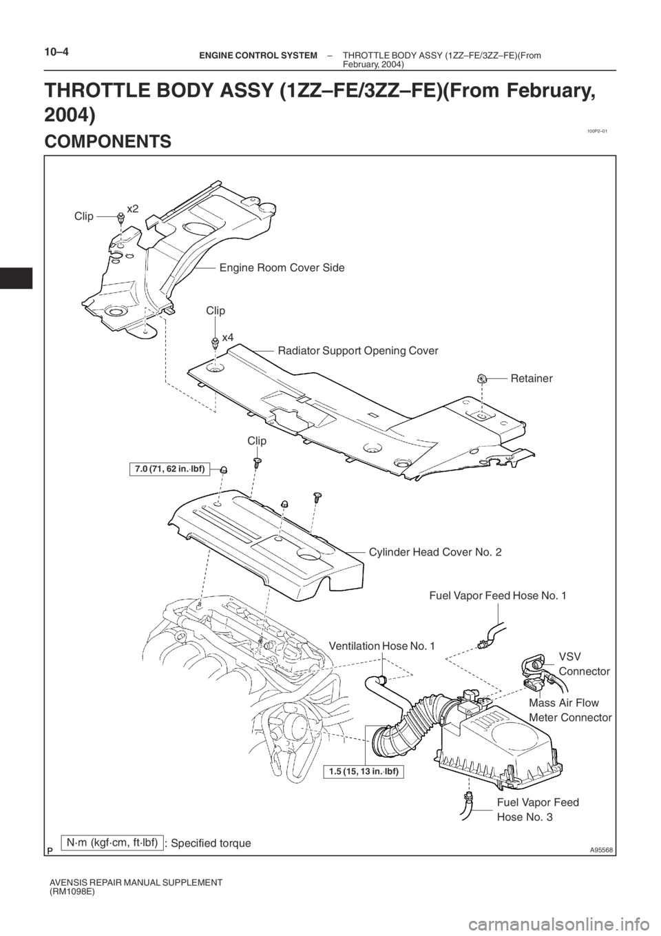
THROTTLE BODY ASSY (1ZZ–FE/3ZZ–FE)(From February,
2004)
COMPONENTS