Page 4466 of 5135
A84701
N·m (kgf·cm, ft·lbf)
: Specified torque
zNon−reusable partzGasketzGasketFuel Tube Sub−assy
Fuel Pipe
Clamp
Fuel Pressure Pulsation
Damper Assy Fuel Pump Assy
zFuel Pump
Insulator
Fuel HoseFuel Pipe Sub−assy No. 1
zFuel Injector Back−up Ring No. 1
zFuel Injector Back−up Ring No. 2
zFuel Injector Back−up Ring No. 3
25 (255, 18)x2
zO−ring
9.0 (92, 80 in.�lbf)
30 (306, 22)
x2
33 (331, 24)
− ENGINE CONTROL SYSTEMKNOCK SENSOR (2AZ−FSE)
10−13
AVENSIS Supplement (RM1045E)
Page 4467 of 5135
A84709
N·m (kgf·cm, ft·lbf)
: Specified torque
zNon−reusable part zIntake Manifold
to Head Gasket No. 1Vacuum Hose
Pressure Sensor
Connector Intake Air Control Valve AssyVSV
ConnectorzIntake to Exhaust
Manifold Gasket Manifold Insulator No. 1
Charcoal Canister
Outlet Hose No. 1
Fuel Hose No. 1
Charcoal Canister
AssyIntake Manifold Vacuum Hose Vacuum Sensor
Connector
Vacuum Sensor
AssyVentilation Hose No. 1
30 (306, 22)
x2
30 (306, 22)
30 (306, 22)
9.5 (97, 84 in.�lbf)x2
x3
5.5 (56, 49 in.�lbf)
10−14
− ENGINE CONTROL SYSTEMKNOCK SENSOR (2AZ−FSE)
AVENSIS Supplement (RM1045E)
Page 4468 of 5135
A88251N·m (kgf·cm, ft·lbf)
: Specified torqueKnock Sensor
Knock Sensor
Connector
Intake Manifold Insulator No. 2
Surge Tank Stay No. 1
x2 Fuel Injector
ConnectorFuel Pressure Sensor
Connector
20 (204, 15)
21 (210, 15)
9.8 (100, 7)
− ENGINE CONTROL SYSTEMKNOCK SENSOR (2AZ−FSE)
10−15
AVENSIS Supplement (RM1045E)
Page 4470 of 5135
(c)
(c)
(b)
(f)
(g)
(d)
(h)
Air Cleaner Clamp
(e)
A84698
(a)
(b)
(c)
A84699
(d)
(e)
(e)
(e)
(e)
A84700
(f)
(f)
(f)
(f)
− ENGINE CONTROL SYSTEMTHROTTLE BODY ASSY (2AZ−FSE)
10−9
AVENSIS")
A81620
(a)(c)
(c)
(b)
(f)
(g)
(d)
(h)
Air Cleaner Clamp
(e)
A84698
(a)
(b)
(c)
A84699
(d)
(e)
(e)
(e)
(e)
A84700
(f)
(f)
(f)
(f)
− ENGINE CONTROL SYSTEMTHROTTLE BODY ASSY (2AZ−FSE)
10−9
AVENSIS Supplement (RM1045E)
6. REMOVE AIR CLEANER CAP SUB−ASSY
(a) Disconnect the mass air flow meter connector.
(b) Disconnect the VSV connector.
(c) Remove the 2 wiring harness clamps.
(d) Disconnect the ventilation hose.
(e) Disconnect the fuel vapor feed hose No. 1.
(f) Disconnect the fuel vapor feed hose No. 2.
(g) Loosen the hose clamp bolt.
(h) Raise the air cleaner clamp up, then the slide it to the air
cleaner cap.
(i) Remove the air cleaner cap together with the air cleaner
hose No. 1.
(j) Remove the air cleaner filter element.
7. REMOVE THROTTLE BODY ASSY
(a) Disconnect the throttle control motor connector.
(b) Remove the bolt.
(c) Unfasten the clip, then remove the wiring harness protec-
tor.
(d) Remove the bolt, then remove the ground terminal.
(e) Remove the 4 bolts, then remove the throttle body brack-
et.
(f) Remove the 4 bolts, then remove the throttle body.
(g) Remove the gasket from the intake manifold.
Page 4472 of 5135
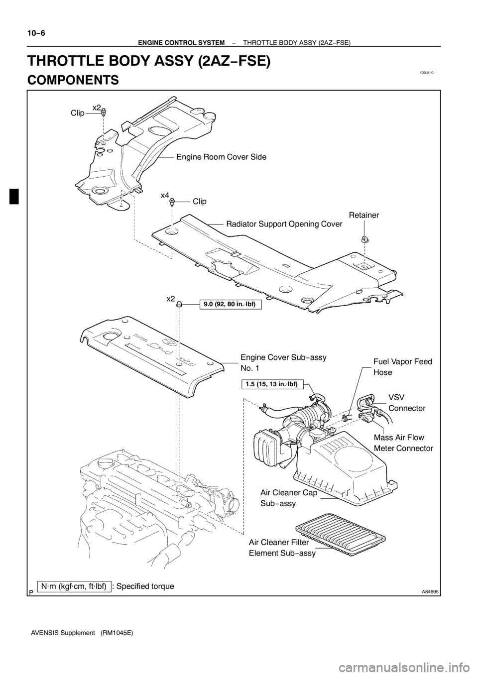
100LW−01
A84695
Mass Air Flow
Meter Connector
N·m (kgf·cm, ft·lbf) : Specified torqueEngine Cover Sub−assy
No. 1
9.0 (92, 80 in.�lbf)
VSV
Connector Fuel Vapor Feed
Hose
Clip
Engine Room Cover Side
Radiator Support Opening Cover
Clip
Retainer
x2
x4
1.5 (15, 13 in.�lbf)
Air Cleaner Filter
Element Sub−assy x2
Air Cleaner Cap
Sub−assy 10−6
− ENGINE CONTROL SYSTEMTHROTTLE BODY ASSY (2AZ−FSE)
AVENSIS Supplement (RM1045E)
THROTTLE BODY ASSY (2AZ−FSE)
COMPONENTS
Page 4535 of 5135
05JLE−01
05−560− DIAGNOSTICSELECTRONIC CONTROLLED AUTOMATIC
TRANSAXLE [ECT] (U151E)
AVENSIS Supplement (RM1045E)
FAIL−SAFE CHART
1. FAIL−SAFE
This function minimizes the loss of the ECT functions when any malfunction occurs in each sensor or sole-
noid.
(a) ATF (Automatic Transmission Fluid) temperature sensor:
When the ATF temperature sensor has a malfunction, 5th upshift is prohibited.
(b) Counter gear speed sensor NC (Speed sensor NC):
When the counter gear speed sensor has a malfunction, 5th upshift is prohibited.
(c) Shift solenoid valve DSL:
When the solenoid valve DSL has a malfunction, the current to the solenoid valve is stopped.
This stops lock−up control, then fuel economy decreases.
Page 4540 of 5135
![TOYOTA AVENSIS 2005 Service Repair Manual FI2547
G23403
Hand−Held Tester
DLC3
05 −554−
DIAGNOSTICS ELECTRONIC CONTROLLED AUTOMATIC
TRANSAXLE [ECT] (U 151E)
AVENSIS Supplement (RM 1045E)
S Freeze frame data:
The freeze frame data record](/manual-img/14/57441/w960_57441-4539.png "TOYOTA AVENSIS 2005 Service Repair Manual FI2547
G23403
Hand−Held Tester
DLC3
05 −554−
DIAGNOSTICS ELECTRONIC CONTROLLED AUTOMATIC
TRANSAXLE [ECT] (U 151E)
AVENSIS Supplement (RM 1045E)
S Freeze frame data:
The freeze frame data record")
FI2547
G23403
Hand−Held Tester
DLC3
05 −554−
DIAGNOSTICS ELECTRONIC CONTROLLED AUTOMATIC
TRANSAXLE [ECT] (U 151E)
AVENSIS Supplement (RM 1045E)
S Freeze frame data:
The freeze frame data records the engine conditions (fuel
system, calculated load, engine coolant temperature, fuel
trim, engine speed, vehicle speed, etc.) when a malfunc-
tion is detected. When troubleshooting, freeze frame data
can help determine if the vehicle was running or stopped,
if the engine was warmed up or not, if the air −fuel ratio
was lean or rich, and other data from the time the malfunc-
tion occurred.
2. DESCRIPTION for M −OBD (Except European spec.)
S When troubleshoot Multiplex OBD (M −OBD) vehicles, the
only difference from the usual troubleshooting procedure
is that you connect the hand −held tester to the vehicle,
and read the various data output from the vehicle’s ECM.
S The vehicle’s on −board computer illuminates the check
engine warning lamp (CHK ENG (MIL)) on the instrument
panel when the computer detects a malfunction in the
computer itself or in drive system components. In addi-
tion, the applicable Diagnostic Trouble Codes (DTCs) are
recorded in the ECM memory (see page 05 −564).
If the malfunction does not recur, the CHK ENG (MIL) goes off
be disappeared by turning the ignition switch to OFF, but the re-
corded DTCs remain in the ECM memory.
S To check the DTCs, connect the hand −held tester to the
Data Link Connector 3 (DLC3) on the vehicle or connect
terminals TC and CG on the DLC3(DTCs will be displayd
on the multi −information display).
S The diagnosis system operates in normal mode during
normal vehicle use. In ”normal mode”, 2 trip detection log-
ic* is used to ensure accurate detection of malfunctions.
A ”check mode”, is also available to technicians as an op-
tion. In ”check mode”, 1 trip detection logic is used for sim-
ulating malfunction symptoms and increasing the sys-
tem’s ability to detect malfunctions, including intermittent
malfunctions (hand −held tester only)
(see page 05 −558).
S*2 trip detection logic:
When a malfunction is first detected, the malfunction is
temporarily stored in the ECM memory ( 1st trip). If the
ignition switch is turned OFF and then ON again, and the
same malfunction is detected again, the CHK ENG (MIL)
will illuminate (2nd trip).
Page 4541 of 5135
![TOYOTA AVENSIS 2005 Service Repair Manual 3 2 145678
910111213141516
DLC33 2 145678
910111213141516
DLC33 2 145678
910111213141516
DLC3
A04550
− DIAGNOSTICSELECTRONIC CONTROLLED AUTOMATIC
TRANSAXLE [ECT] (U151E)05−555
AVENSIS Supplement (](/manual-img/14/57441/w960_57441-4540.png "TOYOTA AVENSIS 2005 Service Repair Manual 3 2 145678
910111213141516
DLC33 2 145678
910111213141516
DLC33 2 145678
910111213141516
DLC3
A04550
− DIAGNOSTICSELECTRONIC CONTROLLED AUTOMATIC
TRANSAXLE [ECT] (U151E)05−555
AVENSIS Supplement (")
3 2 145678
910111213141516
DLC33 2 145678
910111213141516
DLC33 2 145678
910111213141516
DLC3
A04550
− DIAGNOSTICSELECTRONIC CONTROLLED AUTOMATIC
TRANSAXLE [ECT] (U151E)05−555
AVENSIS Supplement (RM1045E)
SFreeze frame data:
The freeze frame data records the engine conditions (fuel
system, calculated load, engine coolant temperature, fuel
trim, engine speed, vehicle speed, etc.) when a malfunc-
tion is detected. When troubleshooting, freeze frame data
can help determine if the vehicle was running or stopped,
if the engine was warmed up or not, if the air−fuel ratio
was lean or rich, and other data from the time the malfunc-
tion occurred.
3. CHECK DLC3.
(a) The vehicle’s ECM uses the ISO 9141−2 (Euro−OBD)/
ISO14230(M−OBD) communication protocol. The termi-
nal arrangement of the DLC3 complies with ISO
15031−03 and matches the ISO 9141−2/ ISO14230 for-
mat.
SymbolTerminal No.NameReference TerminalResultCondition
SIL7Bus ”+” line5−Signal groundPulse generationDuring transmission
CG4Chassis groundBody ground1�or lessAlways
SG5Signal groundBody ground1�or lessAlways
BAT16Battery positiveBody ground9to14VAlways
HINT:
If your display shows ”UNABLE TO CONNECT TO VEHICLE”
when you have connected the cable of hand−held tester to the
DLC3, turned the ignition switch to the ON position and oper-
ated the hand−held tester, there is a problem on the vehicle side
or tool side.
SIf communication is normal when the tool is connected to
another vehicle, inspect DLC3 on the original vehicle.
SIf communication is still not possible when the tool is con-
nected to another vehicle, the problem is probably in the
tool itself, so consult the Service Department listed in the
tool’s instruction manual.
4. INSPECT BATTERY VOLTAGE
(a) Measure the battery voltage.
Battery Voltage:11to14V
If the voltage is below11V, recharge the battery before pro-
ceeding.

: Specified torque
zNon−reusable partzGasketzGasketFuel Tube Sub−assy
Fuel Pipe
Clamp
Fuel Pressure Pulsation
Damper Assy Fuel Pump Assy
zFuel Pump
Insulator
Fuel Ho")

: Specified torque
zNon−reusable part zIntake Manifold
to Head Gasket No. 1Vacuum Hose
Pressure Sensor
Connector Intake Air Control Valve AssyVSV
ConnectorzIntake to E")

: Specified torqueKnock Sensor
Knock Sensor
Connector
Intake Manifold Insulator No. 2
Surge Tank Stay No. 1
x2 Fuel Injector
ConnectorFuel Pressure Sensor
Connector
20 (2")
![TOYOTA AVENSIS 2005 Service Repair Manual 05JLE−01
05−560− DIAGNOSTICSELECTRONIC CONTROLLED AUTOMATIC
TRANSAXLE [ECT] (U151E)
AVENSIS Supplement (RM1045E)
FAIL−SAFE CHART
1. FAIL−SAFE
This function minimizes the loss of the ECT func](/manual-img/14/57441/w960_57441-4534.png "TOYOTA AVENSIS 2005 Service Repair Manual 05JLE−01
05−560− DIAGNOSTICSELECTRONIC CONTROLLED AUTOMATIC
TRANSAXLE [ECT] (U151E)
AVENSIS Supplement (RM1045E)
FAIL−SAFE CHART
1. FAIL−SAFE
This function minimizes the loss of the ECT func")