Page 3088 of 5135
E68141
E67355
Wagon Type:
Automatic Stop Position
Automatic Stop Position Lift Back Type:170� � 3�
160� � 3�
E68111
66±10
± WIPER & WASHERWIPER AND WASHER SYSTEM
AVENSIS REPAIR MANUAL (RM1018E)
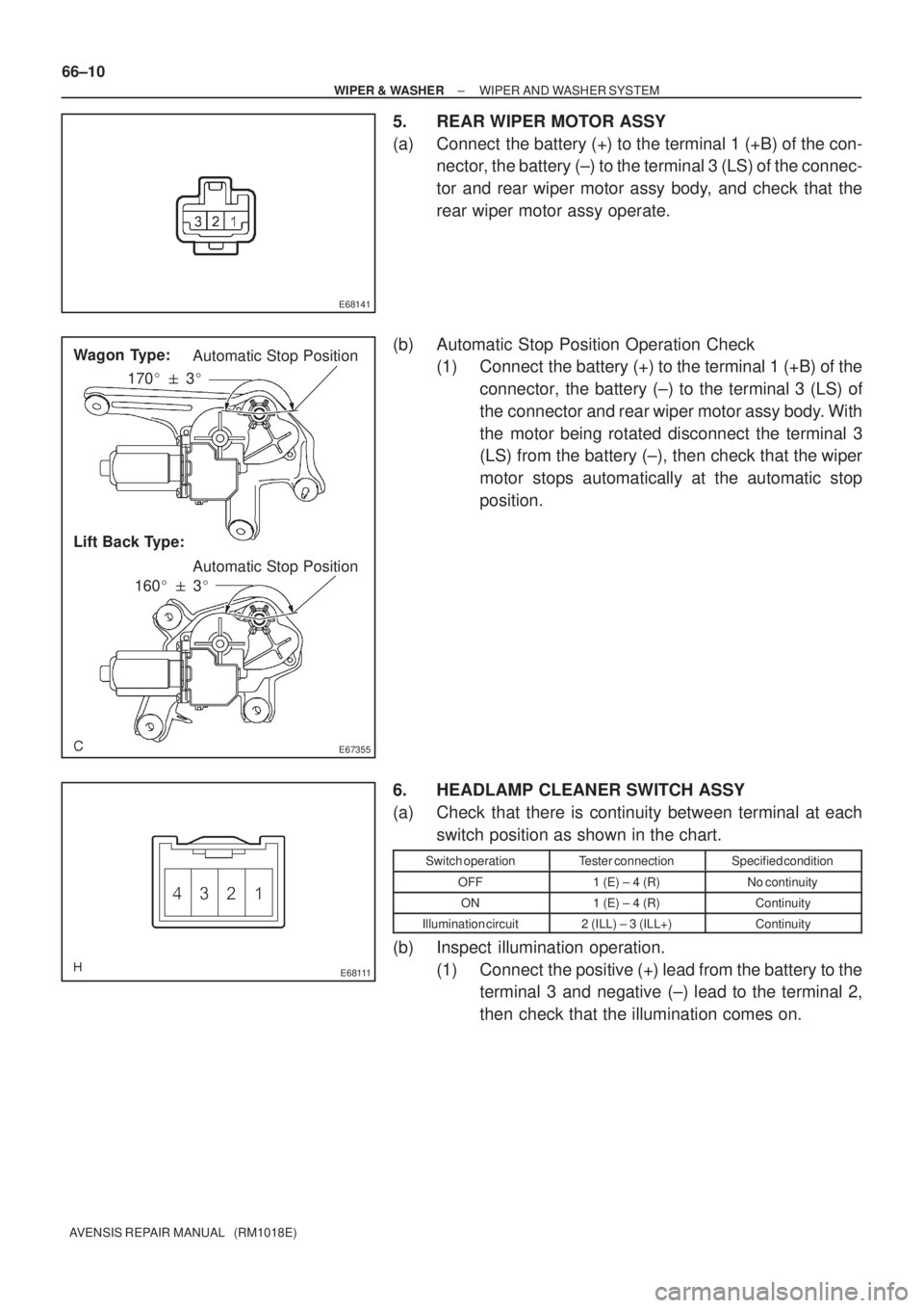
5. REAR WIPER MOTOR ASSY
(a) Connect the battery (+) to the terminal 1 (+B) of the con-
nector, the battery (±) to the terminal 3 (LS) of the connec-
tor and rear wiper motor assy body, and check that the
rear wiper motor assy operate.
(b) Automatic Stop Position Operation Check
(1) Connect the battery (+) to the terminal 1 (+B) of the
connector, the battery (±) to the terminal 3 (LS) of
the connector and rear wiper motor assy body. With
the motor being rotated disconnect the terminal 3
(LS) from the battery (±), then check that the wiper
motor stops automatically at the automatic stop
position.
6. HEADLAMP CLEANER SWITCH ASSY
(a) Check that there is continuity between terminal at each
switch position as shown in the chart.
Switch operationTester connectionSpecified condition
OFF1 (E) ± 4 (R)No continuity
ON1 (E) ± 4 (R)Continuity
Illumination circuit2 (ILL) ± 3 (ILL+)Continuity
(b) Inspect illumination operation.
(1) Connect the positive (+) lead from the battery to the
terminal 3 and negative (±) lead to the terminal 2,
then check that the illumination comes on.
Page 3112 of 5135

650SR±01
������7 8
9 654 3 2 1
10 11 12 13 14 15 16 17I33101
I35771
± LIGHTINGLIGHTING SYSTEM
65±9
AVENSIS REPAIR MANUAL (RM1018E)
INSPECTION
1. HEADLAMP DIMMER SWITCH ASSY
(a) Inspect light control switch continuity.
(1) Check that there is continuity between the terminals
at each switch position as shown in the chart.
Standard:
Switch operationTester connectionSpecified condition
OFF±No continuity
TAIL14 ± 16Continuity
HEAD13 ± 16 ± 14Continuity
(b) Inspect headlight dimmer switch continuity.
(1) Check that there is continuity between the terminals
at each switch position as shown in the chart.
Standard:
Switch operationTester connectionSpecified condition
FLASH7 ± 8 ± 16Continuity
LOW BEAM16 ± 17Continuity
HI BEAM7 ± 16Continuity
(c) Inspect turn signal switch continuity.
(1) Check that there is continuity between the terminals
at each switch position as shown in the chart.
Standard:
Switch operationTester connectionSpecified condition
Right turn2 ± 3Continuity
Neutral±No continuity
Left turn1 ± 2Continuity
(d) Inspect front fog light switch continuity.
(1) Check that there is continuity between the terminals
at each switch position as shown in the chart.
Standard:
Switch operationTester connectionSpecified condition
OFF±No continuity
Front fog switch ON10 ± 11Continuity
Rear fog switch ON10 ± 12Continuity
2. HAZARD WARNING SIGNAL SWITCH ASSY
(a) Check that there is continuity between the terminals at
each switch position as shown in the chart.
Standard:
Switch operationTester connectionSpecified condition
OFF1 ± 4No continuity
ON1 ± 4Continuity
Illumination circuit8 ± 9Continuity
Page 3154 of 5135
I35270
Windshield Wiper Relay
Driver Side Relay Block Assy
Turn Signal Flasher Assy
Rear Fog Lamp Relay
Defogger Relay
Circuit Opening
Relay Assy
Instrument Panel
Junction Block Assy
Fuse Block Assy
LHD:
RHD:
Defogger Relay
Rear Fog Lamp RelayPassenger Side Relay Block Assy
Turn Signal Flasher Assy
Windshield Wiper Relay
Fuse Block Assy
Circuit Opening Relay Assy
Instrument Panel Junction Block Assy
68±2
± WIRINGPOWER SOURCE
AVENSIS REPAIR MANUAL (RM1018E)
Page 3236 of 5135
I30899
Fuel Sender Gauge: 71±4
± INSTRUMENT PANEL/METERCOMBINATION METER
AVENSIS REPAIR MANUAL (RM1018E)
3. INSPECT TACHOMETER
(a) Check the operation
(1) Connect a tune±up test tachometer, and start the engine.
NOTICE:
�Reversing the connection of the tachometer will damage the transistors and the insides of the
diodes .
�When removing or installing the tachometer, be careful not to drop or subject it to heavy
shocks.
(2) Compare the result of the test with standard indication.
DC 13.5 V, 25 �C at (77 �F)
Standard indication (r/min)Acceptable range (r/min)
Data in ( ) are for reference
700630 ± 770
1,000(900 ± 1100)
2,000(1850 ± 2150)
3,0002800 ± 3200
4,000(3800 ± 4200)
5,0004800 ± 5200
6,000(5750 ± 6250)
7,0006700 ± 7300
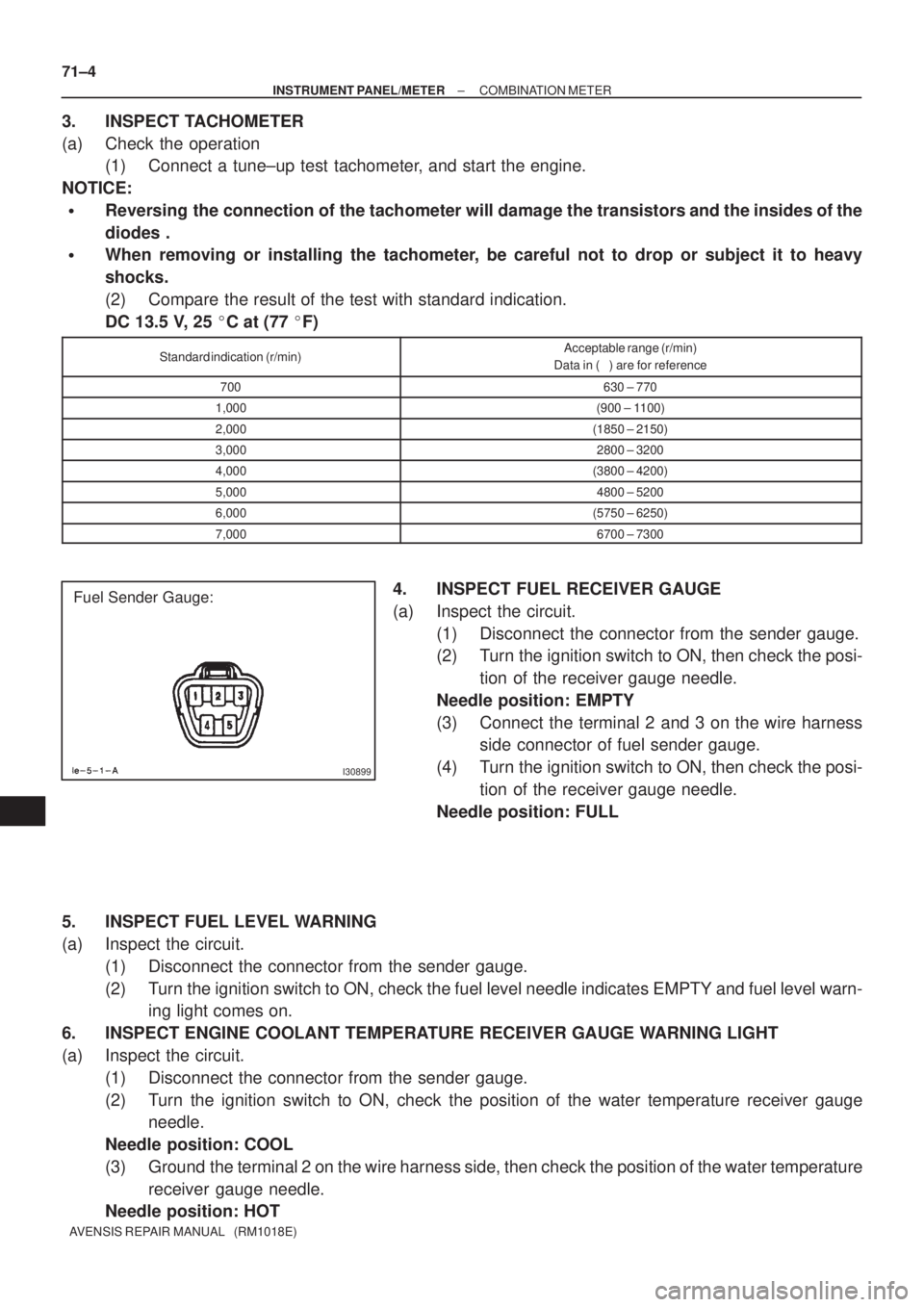
4. INSPECT FUEL RECEIVER GAUGE
(a) Inspect the circuit.
(1) Disconnect the connector from the sender gauge.
(2) Turn the ignition switch to ON, then check the posi-
tion of the receiver gauge needle.
Needle position: EMPTY
(3) Connect the terminal 2 and 3 on the wire harness
side connector of fuel sender gauge.
(4) Turn the ignition switch to ON, then check the posi-
tion of the receiver gauge needle.
Needle position: FULL
5. INSPECT FUEL LEVEL WARNING
(a) Inspect the circuit.
(1) Disconnect the connector from the sender gauge.
(2) Turn the ignition switch to ON, check the fuel level needle indicates EMPTY and fuel level warn-
ing light comes on.
6. INSPECT ENGINE COOLANT TEMPERATURE RECEIVER GAUGE WARNING LIGHT
(a) Inspect the circuit.
(1) Disconnect the connector from the sender gauge.
(2) Turn the ignition switch to ON, check the position of the water temperature receiver gauge
needle.
Needle position: COOL
(3) Ground the terminal 2 on the wire harness side, then check the position of the water temperature
receiver gauge needle.
Needle position: HOT
Page 3237 of 5135
IG
SPEED
BKL SW
(D±seat)
BKL SW
(P seat)
WRN LAMP
BUZZERON
OFF
15km/h
0
BELT ON
BELT OFF
LVL1
LVL2 BELT ON
BELT OFF
ON
OFF OFF
30s
90s30s
90s
± INSTRUMENT PANEL/METERCOMBINATION METER
71±5
AVENSIS REPAIR MANUAL (RM1018E)
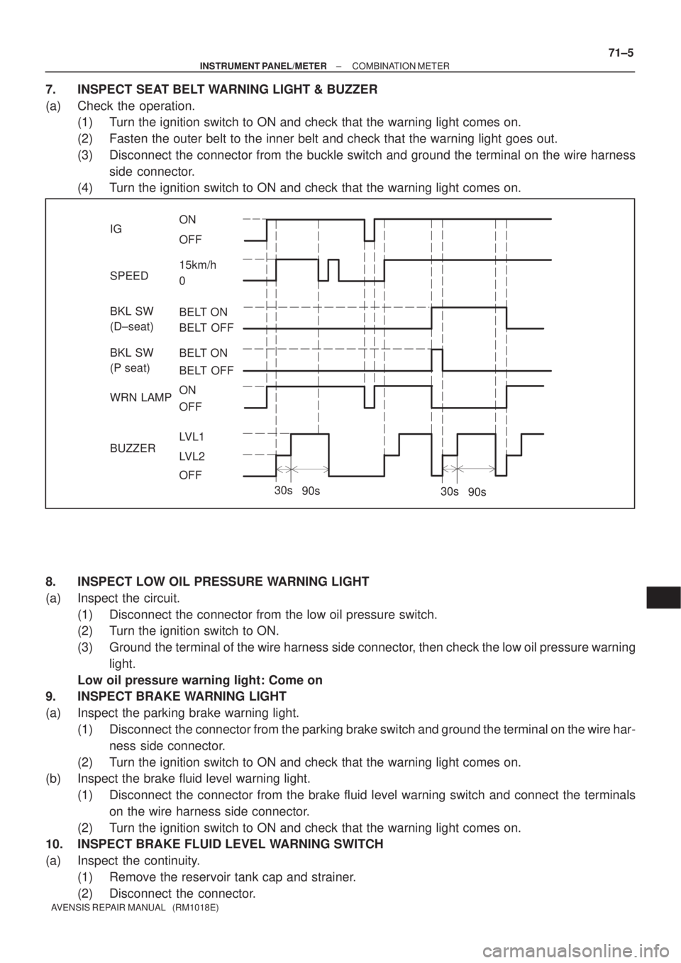
7. INSPECT SEAT BELT WARNING LIGHT & BUZZER
(a) Check the operation.
(1) Turn the ignition switch to ON and check that the warning light comes on.
(2) Fasten the outer belt to the inner belt and check that the warning light goes out.
(3) Disconnect the connector from the buckle switch and ground the terminal on the wire harness
side connector.
(4) Turn the ignition switch to ON and check that the warning light comes on.
8. INSPECT LOW OIL PRESSURE WARNING LIGHT
(a) Inspect the circuit.
(1) Disconnect the connector from the low oil pressure switch.
(2) Turn the ignition switch to ON.
(3) Ground the terminal of the wire harness side connector, then check the low oil pressure warning
light.
Low oil pressure warning light: Come on
9. INSPECT BRAKE WARNING LIGHT
(a) Inspect the parking brake warning light.
(1) Disconnect the connector from the parking brake switch and ground the terminal on the wire har-
ness side connector.
(2) Turn the ignition switch to ON and check that the warning light comes on.
(b) Inspect the brake fluid level warning light.
(1) Disconnect the connector from the brake fluid level warning switch and connect the terminals
on the wire harness side connector.
(2) Turn the ignition switch to ON and check that the warning light comes on.
10. INSPECT BRAKE FLUID LEVEL WARNING SWITCH
(a) Inspect the continuity.
(1) Remove the reservoir tank cap and strainer.
(2) Disconnect the connector.
Page 3239 of 5135
710CM±02
±
INSTRUMENT PANEL/METER COMBINATION METER
71±1
AVENSIS REPAIR MANUAL (RM1018E)
COMBINATION METER
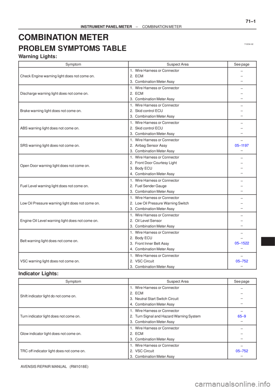
PROBLEM SYMPTOMS TABLE
Warning Lights:
SymptomSuspect AreaSee page
Check Engine warning light does not come on.
1.Wire Harness or Connector
2.ECM
3.Combination Meter Assy±
±
±
Discharge warning light does not come on.
1.Wire Harness or Connector
2.ECM
3.Combination Meter Assy±
±
±
Brake warning light does not come on.
1.Wire Harness or Connector
2.Skid control ECU
3.Combination Meter Assy±
±
±
ABS warning light does not come on.
1.Wire Harness or Connector
2.Skid control ECU
3.Combination Meter Assy±
±
±
SRS warning light does not come on.
1.Wire Harness or Connector
2.Airbag Sensor Assy
3.Combination Meter Assy±
05±1197 ±
Open Door warning light does not come on.
1.Wire Harness or Connector
2.Front Door Courtesy Light
3.Body ECU
4.Combination Meter Assy±
±
±
±
Fuel Level warning light does not come on.
1.Wire Harness or Connector
2.Fuel Sender Gauge
3.Combination Meter Assy±
±
±
Low Oil Pressure warning light does not come on.
1.Wire Harness or Connector
2.Low Oil Pressure Warning Switch
3.Combination Meter Assy±
±
±
Engine Oil Level warning light does not come on.
1.Wire Harness or Connector
2.Oil Level Sensor
3.Combination Meter Assy±
±
±
Belt warning light does not come on.
1.Wire Harness or Connector
2.Body ECU
3.Front Inner Belt Assy
4.Combination Meter Assy±
±
05±1522
±
VSC warning light does not come on.
1.Wire Harness or Connector
2.VSC Circuit
3.Combination Meter Assy±
05±752 ±
Indicator Lights:
SymptomSuspect AreaSee page
Shift indicator light do not come on.
1. Wire Harness or Connector
2. ECM
3. Neutral Start Switch Circuit
4. Combination Meter Assy±
±
±
±
Turn indicator light does not come on.
1. Wire Harness or Connector
2. Turn Signal and Hazard Warning System
3. Combination Meter Assy±
65±9 ±
Glow indicator light does not come on.
1. Wire Harness or Connector
2. ECM
3. Combination Meter Assy±
±
±
TRC off indicator light does not come on.
1. Wire Harness or Connector
2. VSC Circuit
3. Combination Meter Assy±
05±752 ±
Page 3462 of 5135
010B9±09
± INTRODUCTIONTERMS
01±7
1AZ±FSE ENGINE REPAIR MANUAL (RM1019E)
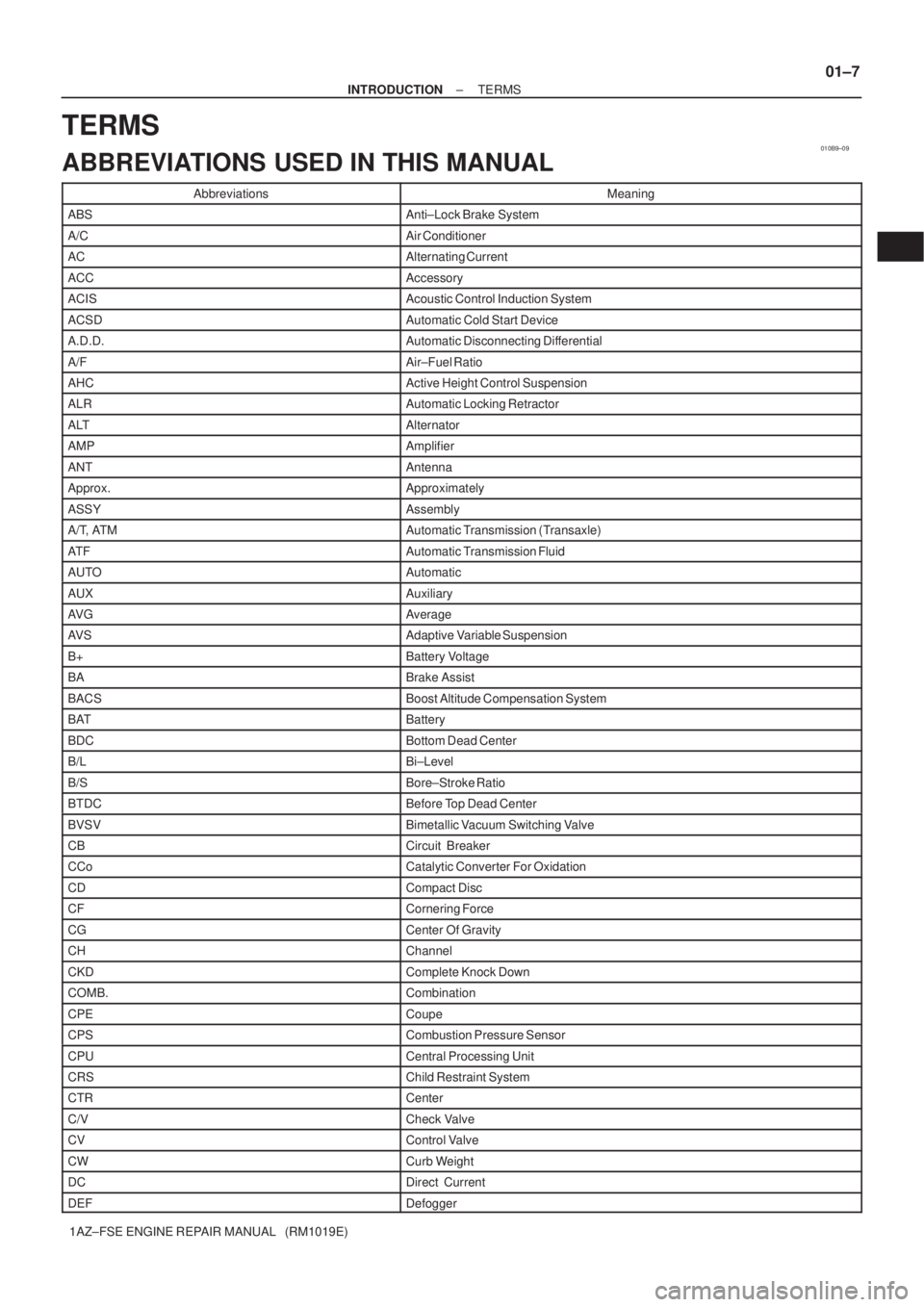
TERMS
ABBREVIATIONS USED IN THIS MANUAL
AbbreviationsMeaning
ABSAnti±Lock Brake System
A/CAir Conditioner
ACAlternating Current
ACCAccessory
ACISAcoustic Control Induction System
ACSDAutomatic Cold Start Device
A.D.D.Automatic Disconnecting Differential
A/FAir±Fuel Ratio
AHCActive Height Control Suspension
ALRAutomatic Locking Retractor
ALTAlternator
AMPAmplifier
ANTAntenna
Approx.Approximately
ASSYAssembly
A/T, ATMAutomatic Transmission (Transaxle)
AT FAutomatic Transmission Fluid
AUTOAutomatic
AUXAuxiliary
AV GAverage
AV SAdaptive Variable Suspension
B+Battery Voltage
BABrake Assist
BACSBoost Altitude Compensation System
BATBattery
BDCBottom Dead Center
B/LBi±Level
B/SBore±Stroke Ratio
BTDCBefore Top Dead Center
BVSVBimetallic Vacuum Switching Valve
CBCircuit Breaker
CCoCatalytic Converter For Oxidation
CDCompact Disc
CFCornering Force
CGCenter Of Gravity
CHChannel
CKDComplete Knock Down
COMB.Combination
CPECoupe
CPSCombustion Pressure Sensor
CPUCentral Processing Unit
CRSChild Restraint System
CTRCenter
C/VCheck Valve
CVControl Valve
CWCurb Weight
DCDirect Current
DEFDefogger
Page 3464 of 5135
± INTRODUCTIONTERMS
01±9
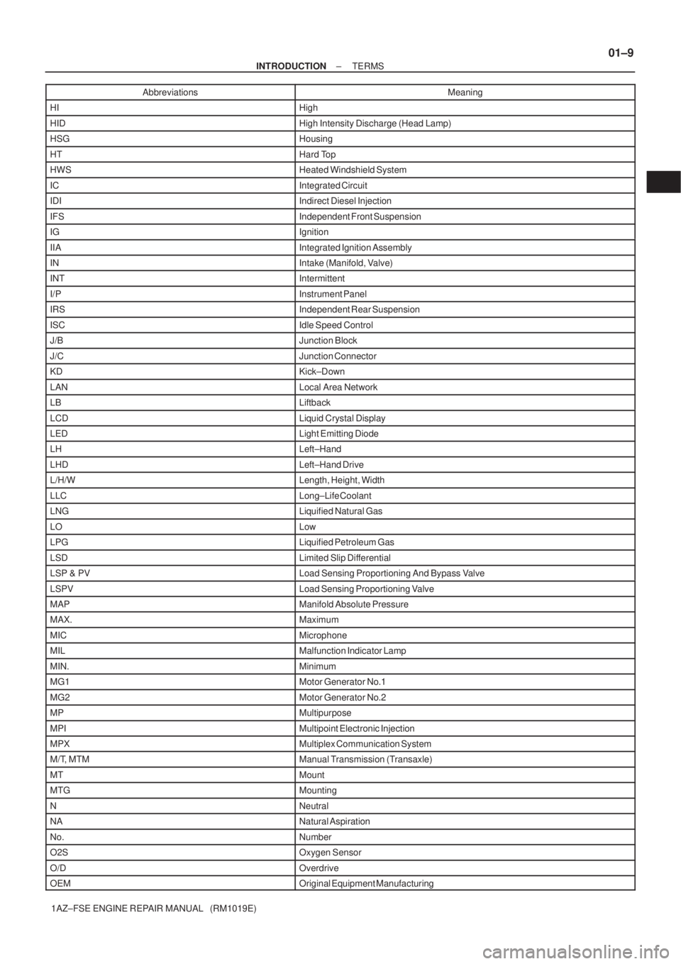
1AZ±FSE ENGINE REPAIR MANUAL (RM1019E)Abbreviations Meaning
HIHigh
HIDHigh Intensity Discharge (Head Lamp)
HSGHousing
HTHard Top
HWSHeated Windshield System
ICIntegrated Circuit
IDIIndirect Diesel Injection
IFSIndependent Front Suspension
IGIgnition
IIAIntegrated Ignition Assembly
INIntake (Manifold, Valve)
INTIntermittent
I/PInstrument Panel
IRSIndependent Rear Suspension
ISCIdle Speed Control
J/BJunction Block
J/CJunction Connector
KDKick±Down
LANLocal Area Network
LBLiftback
LCDLiquid Crystal Display
LEDLight Emitting Diode
LHLeft±Hand
LHDLeft±Hand Drive
L/H/WLength, Height, Width
LLCLong±Life Coolant
LNGLiquified Natural Gas
LOLow
LPGLiquified Petroleum Gas
LSDLimited Slip Differential
LSP & PVLoad Sensing Proportioning And Bypass Valve
LSPVLoad Sensing Proportioning Valve
MAPManifold Absolute Pressure
MAX.Maximum
MICMicrophone
MILMalfunction Indicator Lamp
MIN.Minimum
MG1Motor Generator No.1
MG2Motor Generator No.2
MPMultipurpose
MPIMultipoint Electronic Injection
MPXMultiplex Communication System
M/T, MTMManual Transmission (Transaxle)
MTMount
MTGMounting
NNeutral
NANatural Aspiration
No.Number
O2SOxygen Sensor
O/DOverdrive
OEMOriginal Equipment Manufacturing