Page 1793 of 5135
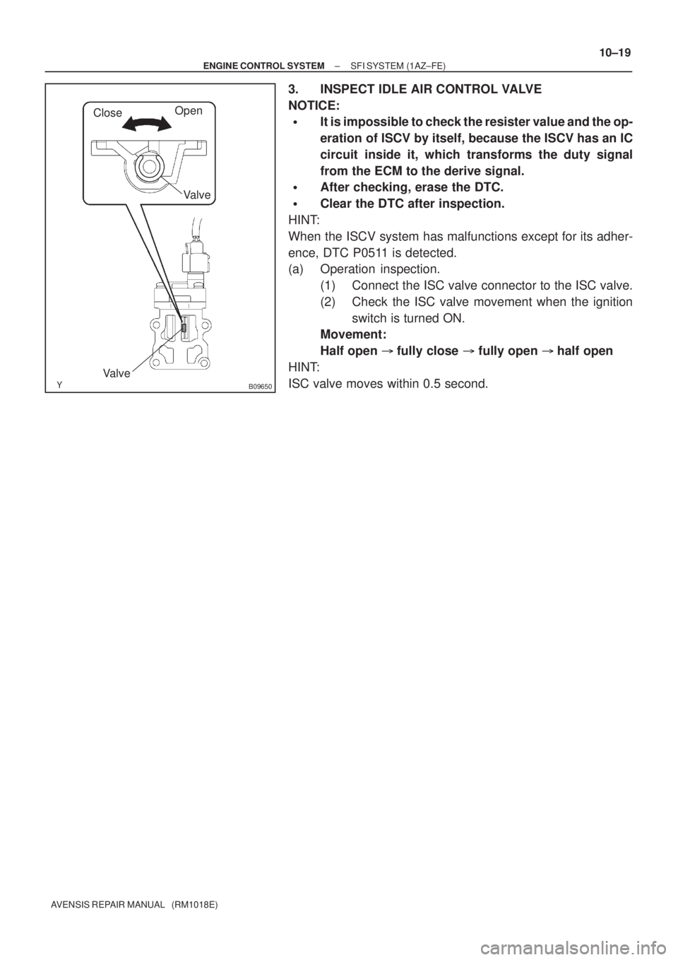
CloseOpen
Valve
Valve
B09650
± ENGINE CONTROL SYSTEMSFI SYSTEM (1AZ±FE)
10±19
AVENSIS REPAIR MANUAL (RM1018E)
3. INSPECT IDLE AIR CONTROL VALVE
NOTICE:
�It is impossible to check the resister value and the op-
eration of ISCV by itself, because the ISCV has an IC
circuit inside it, which transforms the duty signal
from the ECM to the derive signal.
�After checking, erase the DTC.
�Clear the DTC after inspection.
HINT:
When the ISCV system has malfunctions except for its adher-
ence, DTC P0511 is detected.
(a) Operation inspection.
(1) Connect the ISC valve connector to the ISC valve.
(2) Check the ISC valve movement when the ignition
switch is turned ON.
Movement:
Half open �fully close � fully open �half open
HINT:
ISC valve moves within 0.5 second.
Page 1808 of 5135
A60553
10±6
± ENGINE CONTROL SYSTEMSFI SYSTEM (1ZZ±FE/3ZZ±FE)
AVENSIS REPAIR MANUAL (RM1018E)
8. INSPECT CIRCUIT OPENING RELAY
(a) Inspect the relay continuity.
(1) Using an ohmmeter, check that there is continuity
between terminals 1 and 2.
Specified condition: Continuity
(2) Check that there is no continuity between terminals
3 and 5.
Specified condition: No continuity
(b) Inspect the relay operation.
(1) Apply battery voltage across terminals 1 and 2.
(2) Using an ohmmeter, check that there is continuity
between terminals 3 and 5.
Specified condition: Continuity
Page 1829 of 5135
E34090
± ENGINE CONTROL SYSTEMSFI SYSTEM (1AZ±FSE)
10±41
AVENSIS REPAIR MANUAL (RM1018E)
7. INSPECT CIRCUIT OPENING RELAY
(a) Inspect the relay continuity.
(1) Using an ohmmeter, check that there is continuity
between terminals 1 and 2.
Specified condition: Continuity
(2) Check that there is no continuity between terminals
3 and 5.
Specified condition: No continuity
(b) Inspect the relay operation.
(1) Apply battery voltage across terminals 1 and 2.
(2) Using an ohmmeter, check that there is continuity
between terminals 3 and 5.
Specified condition: Continuity
Page 1936 of 5135

AVENSIS REP")
A77115
Ohmmeter
Resistance
A77116
Ohmmeter
No continuity
A77117
Air E F
A77118
Air E
F
Battery
A64543
+B
Bank 2 Sensor 1:
HT
E1
12±14
± EMISSION CONTROLEMISSION CONTROL SYSTEM (1AZ±FSE)
AVENSIS REPAIR MANUAL (RM1018E)
4. INSPECT VACUUM SWITCHING VALVE ASSY NO.1
(a) Inspect VSV for open circuit.
(1) Using an ohmmeter, measure resistance between
the terminals.
Resistance: 26 to 30 � at 20�C (68�F)
If the resistance is not as specified, replace the VSV.
(b) Inspect the VSV for ground.
(1) Using an ohmmeter, check that there is no continu-
ity between each terminal and the body.
If there is continuity, replace the VSV.
(c) Inspect the VSV operation.
(1) Check that air flows with a little difficulty from port E
to port F.
(2) Apply battery voltage across the terminals.
(3) Check that air flows from port E to port F.
If operation is not as specified, replace the VSV.
5. INSPECT HEATED OXYGEN SENSOR
(a) Bank 2 Sensor 1:
(1) Using an ohmmeter, measure the resistance be-
tween the terminals.
Resistance:
Terminal No.Resistance
1 (HT) ± 2 (+B)11 to 16 � at 20 �C (68 �F)
1 (HT) ± 4 (E1)No Continuity
If the resistance is not as specified, replace the sensor.
Page 1941 of 5135

12±9
AVENSIS REPAI")
A77115
Ohmmeter
Resistance
A77116
Ohmmeter
No continuity
A77117
Air E F
A77118
Air E
F
Battery
A61829
+B HT
E1 Bank 1 Sensor 1:
± EMISSION CONTROLEMISSION CONTROL SYSTEM (1AZ±FE)
12±9
AVENSIS REPAIR MANUAL (RM1018E)
4. INSPECT VACUUM SWITCHING VALVE ASSY NO.1
(a) Inspect VSV for open circuit.
(1) Using an ohmmeter, measure resistance between
the terminals.
Resistance: 26 to 30 � at 20�C (68�F)
If the resistance is not as specified, replace the VSV.
(b) Inspect the VSV for ground.
(1) Using an ohmmeter, check that there is no continu-
ity between each terminal and the body.
If there is continuity, replace the VSV.
(c) Inspect the VSV operation.
(1) Check that air flows with a little difficulty from port E
to port F.
(2) Apply battery voltage across the terminals.
(3) Check that air flows from port E to port F.
If operation is not as specified, replace the VSV.
5. INSPECT AIR FUEL RATIO SENSOR
(a) Bank 1 Sensor 1:
(1) Using an ohmmeter, measure the resistance be-
tween the terminals.
Resistance:
Terminal No.Resistance
1 (HT) ± 2 (+B)1.8 to 3.4 � at 20 �C (68 �F)
1 (HT) ± (+B)5.0 to 7.5 � at 500 �C (932 �F)
1 (HT) ± 4 (E1)No Continuity
If the resistance is not as specified, replace the sensor.
Page 1945 of 5135

12±3
AVENSIS REPAIR MANUAL")
1209D±02
A62250
Port A
Port BPort C
A77115
Ohmmeter
Resistance
A77116
Ohmmeter
No continuity
A77117
Air E F
± EMISSION CONTROLEMISSION CONTROL SYSTEM (1ZZ±FE/3ZZ±FE)
12±3
AVENSIS REPAIR MANUAL (RM1018E)
INSPECTION
1. INSPECT CHARCOAL CANISTER ASSY
(a) Inspect charcoal canister operation.
(1) Check the charcoal canister operation according to
the table below.
SST 09992±00242
Inspection:
Checking methodResult
Close ports B and C, then apply vacuum
to port ANo leaks
Close port C, then apply vacuum to port
AAir flows from port B
Close port C, then blow air into port AAir flows from port B
Blow air into port AAir flows from ports B and C
2. INSPECT VACUUM SWITCHING VALVE ASSY NO.1
(a) Inspect VSV for open circuit.
(1) Using an ohmmeter, measure resistance between
the terminals.
Resistance: 26 to 30 � at 20�C (68�F)
If the resistance is not as specified, replace the VSV.
(b) Inspect the VSV for ground.
(1) Using an ohmmeter, check that there is no continu-
ity between each terminal and the body.
If there is continuity, replace the VSV.
(c) Inspect the VSV operation.
(1) Check that air flows with a little difficulty from port E
to port F.
Page 2002 of 5135
13030±02
A60591
A60592
A60593
Air
E
G
A60594
Air
Filter
Battery E
± INTAKETURBO CHARGER SYSTEM (1CD±FTV)
13±7
AVENSIS REPAIR MANUAL (RM1018E)
INSPECTION
1. VACUUM SWITCHING VALVE ASSY NO.1
(a) Inspect VSV for open circuit.
(1) Using an ohmmeter, check that the there is continu-
ity between the terminals.
Resistance: 37 ± 44 � at 20�C (68�F)
(b) Inspect VSV for ground.
(1) Using an ohmmeter, check that there is no continu-
ity between each terminal and the body.
Specified condition: No continuity
(c) Inspect VSV operation.
(1) Check that air flows from port E to G.
(2) Apply battery voltage across the terminals.
(3) Check that air flows from port E to filter.
Page 2009 of 5135

AVENSIS REPAIR MANUAL (RM1018E)
INSPECTION
1. INSPECT")
1209J±02
A77127
Ohmmeter
Resistance
A77128No ContinuityOhmmeter
A77129
Vacuum
A77130
6V Vacuum 12±18
± EMISSION CONTROLEGR SYSTEM (1CD±FTV)
AVENSIS REPAIR MANUAL (RM1018E)
INSPECTION
1. INSPECT VACUUM REGULATING VALVE ASSY
(a) Inspect E±VRV for open circuit
(1) Using an ohmmeter, measure resistance between
the terminals.
Resistance:
10 to 14 � at 20�C (68�F)
(b) Inspect E±VRV for ground
(1) Using an ohmmeter, check that there is no continu-
ity between each terminal and the body.
Specified condition : No continuity
(c) Inspect E±VRV for air tightness
(1) Apply vacuum to the vacuum output port. Check
that the needle of vacuum pump indicates an in-
crease of 66.7 kPa (500 mmHg, 19.7 in.Hg) or
more.
If the air tightness is not as specified, replace the E±VRV.
(d) Inspect E±VRV operation
(1) Apply about 4 dry batteries of 1.5V in series.
(2) Check that the need does not move when vacuum
is applied to the vacuum outlet port.
If operation is not as specified, replace the E±VRV.

AVENSIS REPAIR MANUAL (RM1018E)
8. INSPECT CIRCUIT OPENING RELAY
(a) Inspect the relay continuity.
(1) Using an ohmmeter, check that")

10±41
AVENSIS REPAIR MANUAL (RM1018E)
7. INSPECT CIRCUIT OPENING RELAY
(a) Inspect the relay continuity.
(1) Using an ohmmeter, check that there")

13±7
AVENSIS REPAIR MANUAL (RM1018E)
INSPECTION
1. VACUUM SWITCHING VALVE ASSY NO.1
(a) I")