Page 2431 of 5135
±
COOLING WATER PUMP ASSY(1CD±FTV)
16±49
AVENSIS REPAIR MANUAL (RM1018E)
41.SET NO. 1 CYLINDER TO TDC/COMPRESSION
SST09960±10010 (09962±01000, 09963±01000)
42.INSTALL TIMING BELT(See page 14±307)
43.CHECK VALVE TIMING(See page 14±307)
44.INSTALL TIMING CHAIN COVER PLATE(See page 14±307)
45.INSTALL TRANSVERSE ENGINE ENGINE MOUNTING BRACKET(See page 14±307)
46.INSTALL TIMING BELT GUIDE(See page 14±307)
47.INSTALL TIMING BELT NO.1 COVER(See page 14±307)
48.INSTALL TIMING BELT NO.2 COVER(See page 14±307)
49.INSTALL IDLER PULLEY SUB±ASSY(See page 11±69)
50.INSTALL CRANKSHAFT PULLEY(See page 14±307) SST 09213±54015 (90105±08076), 09330±00021
51.INSTALL ENGINE MOUNTING INSULATOR SUB±ASSY RH(See page 14±307)
52.INSTALL POWER STEERING IDLE PULLEY BRACKET (See page 14±286)
53.ADJUST V (COOLER COMPRESSOR TO CRANKSHAFT PULLEY) BELT NO.1 (See page 14±269)
54.INSTALL INJECTOR DRIVER(See page 11±69)
55. INSTALL FRONT WHEEL RH Torque: 103 N �m (1,050 kgf �cm, 76 ft �lbf)
56. INSTALL ENGINE COVER NO.1
Torque: 8.0 N �m (82 kgf �cm, 71 in. �lbf)
57.ADD ENGINE COOLANT(See page 16±44)
58.CHECK FOR ENGINE COOLANT LEAKS(See page 16±44)
59.CHECK FOR FUEL LEAKS(See page 11±60)
Page 2578 of 5135
320W7±01
F40019
F42620
±
BRAKE BRAKE BOOSTER ASSY (LHD)
32±19
AVENSIS REPAIR MANUAL (RM1018E)
REPLACEMENT
NOTICE:
Do not adjust the brake booster push rod.
1. DRAIN BRAKE FLUID
NOTICE:
Wash the brake fluid off immediately if it adheres to any painted surface\
.
2. REMOVE AIR CLEANER ASSEMBLY WITH HOSE
3. SEPARATE ENGINE ROOM RELAY BLOCK
4. REMOVE CHARCOAL CANISTER ASSY (GASOLINE ENGINE TYPE)
5.REMOVE FUEL FILTER ASSY (DIESEL ENGINE TYPE) (See page 11±82)
6.REMOVE BRAKE MASTER CYLINDER SUB±ASSY (See page 32±13)
(a) w/o VSC:
SST 09023±00100
(b) w/ VSC: SST 09023±38400
7.REMOVE HEATER ASSY (W/ COLD AREA) (See page 55±100)
8. REMOVE FRONT WHEEL LH
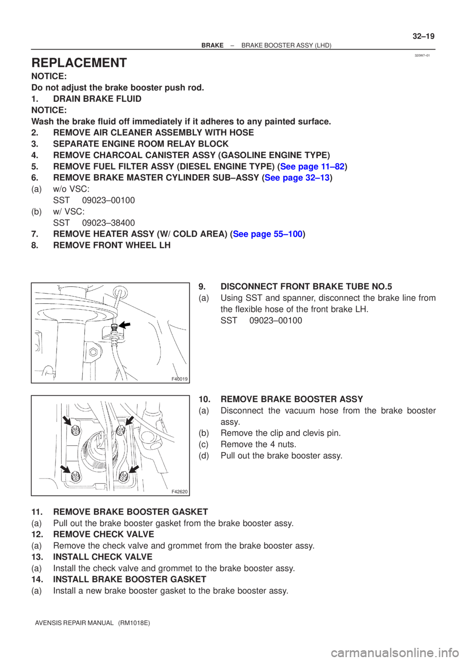
9. DISCONNECT FRONT BRAKE TUBE NO.5
(a) Using SST and spanner, disconnect the brake line fromthe flexible hose of the front brake LH.
SST 09023±00100
10. REMOVE BRAKE BOOSTER ASSY
(a) Disconnect the vacuum hose from the brake booster assy.
(b) Remove the clip and clevis pin.
(c) Remove the 4 nuts.
(d) Pull out the brake booster assy.
11. REMOVE BRAKE BOOSTER GASKET
(a) Pull out the brake booster gasket from the brake booster assy.
12. REMOVE CHECK VALVE
(a) Remove the check valve and grommet from the brake booster assy.
13. INSTALL CHECK VALVE
(a) Install the check valve and grommet to the brake booster assy.
14. INSTALL BRAKE BOOSTER GASKET
(a) Install a new brake booster gasket to the brake booster assy.
Page 2579 of 5135
F42620
F40019
32±20
±
BRAKE BRAKE BOOSTER ASSY (LHD)
AVENSIS REPAIR MANUAL (RM1018E)
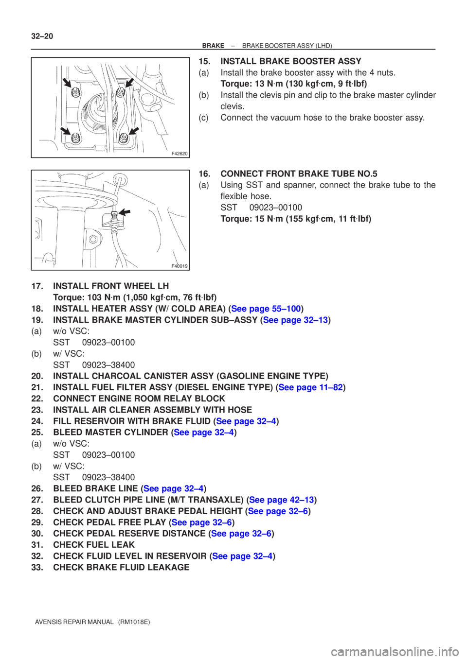
15. INSTALL BRAKE BOOSTER ASSY
(a) Install the brake booster assy with the 4 nuts. Torque: 13 N �m (130 kgf �cm, 9 ft �lbf)
(b) Install the clevis pin and clip to the brake master cylinder clevis.
(c) Connect the vacuum hose to the brake booster assy.
16. CONNECT FRONT BRAKE TUBE NO.5
(a) Using SST and spanner, connect the brake tube to the flexible hose.
SST 09023±00100
Torque: 15 N �m (155 kgf �cm, 11 ft �lbf)
17. INSTALL FRONT WHEEL LH Torque: 103 N �m (1,050 kgf �cm, 76 ft �lbf)
18.INSTALL HEATER ASSY (W/ COLD AREA) (See page 55±100)
19.INSTALL BRAKE MASTER CYLINDER SUB±ASSY (See page 32±13)
(a) w/o VSC: SST 09023±00100
(b) w/ VSC: SST 09023±38400
20. INSTALL CHARCOAL CANISTER ASSY (GASOLINE ENGINE TYPE)
21.INSTALL FUEL FILTER ASSY (DIESEL ENGINE TYPE) (See page 11±82)
22. CONNECT ENGINE ROOM RELAY BLOCK
23. INSTALL AIR CLEANER ASSEMBLY WITH HOSE
24.FILL RESERVOIR WITH BRAKE FLUID (See page 32±4)
25.BLEED MASTER CYLINDER (See page 32±4)
(a) w/o VSC:
SST 09023±00100
(b) w/ VSC: SST 09023±38400
26.BLEED BRAKE LINE (See page 32±4)
27.BLEED CLUTCH PIPE LINE (M/T TRANSAXLE) (See page 42±13)
28.CHECK AND ADJUST BRAKE PEDAL HEIGHT (See page 32±6)
29.CHECK PEDAL FREE PLAY (See page 32±6)
30.CHECK PEDAL RESERVE DISTANCE (See page 32±6)
31. CHECK FUEL LEAK
32.CHECK FLUID LEVEL IN RESERVOIR (See page 32±4)
33. CHECK BRAKE FLUID LEAKAGE
Page 2580 of 5135
320VU±01
F45162
Vacuum Hose
ClipBrake Vacuum
Check Valve
Check Valve
Grommet
Clevis Pin
Clip Wave Washer
13 (130, 9)
Engine Room Relay Block Way
Clutch Reservoir Tube M/T Transaxle:
Front Brake
Tube No.5
15 (155, 11) *1
29 (296, 21) *2
Brake Fluid Level
Switch Connector
� Brake Booster Gasket
20 (204, 15)
20 (204, 15)
Brake Master
Cylinder Sub±assy
� Brake Booster Assy
Brake Master
Cylinder clevis
15 (155, 11)
Fuel Filter Assy Diesel Engine Type: Heater Assy w/ Cold Area:
Air Cleaner Assembly
With Hose
Clutch Tube M/T Transaxle:Gasoline Engine Type:
15 (155, 11)
*1
w/ ABS:
*2
w/ VSC:N�m (kgf�cm, ft�lbf) : Specified torque
5.4 (55, 48 in.�lbf)
Charcoal Canister
Assy
32±18
± BRAKEBRAKE BOOSTER ASSY (LHD)
AVENSIS REPAIR MANUAL (RM1018E)
COMPONENTS
Page 2582 of 5135
320W6±01
G24218
G24217
F45393
± BRAKEBRAKE MASTER CYLINDER SUB±ASSY
32±13
AVENSIS REPAIR MANUAL (RM1018E)
REPLACEMENT
NOTICE:
Do not adjust the brake booster push rod.
1. DRAIN BRAKE FLUID
NOTICE:
Wash the brake fluid off immediately if it adheres to any painted surface.
2. REMOVE ENGINE ROOM RELAY BLOCK (LHD STEERING POSITION TYPE)
3. REMOVE AIR CLEANER CAP SUB±ASSY (LHD STEERING POSITION TYPE)
4. REMOVE CHARCOAL CANISTER ASSY (LHD STEERING POSITION TYPE)
5. REMOVE FUEL FILTER ASSY (LHD STEERING POSITION TYPE)
(a) Diesal engine type:
Remove the fuel filter assy with the 3 bolts.
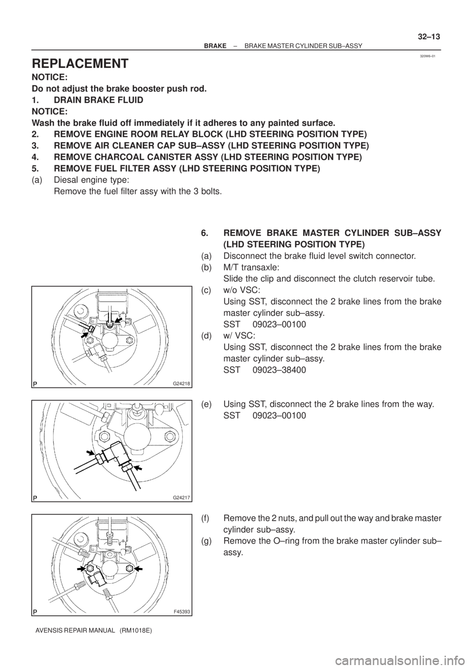
6. REMOVE BRAKE MASTER CYLINDER SUB±ASSY
(LHD STEERING POSITION TYPE)
(a) Disconnect the brake fluid level switch connector.
(b) M/T transaxle:
Slide the clip and disconnect the clutch reservoir tube.
(c) w/o VSC:
Using SST, disconnect the 2 brake lines from the brake
master cylinder sub±assy.
SST 09023±00100
(d) w/ VSC:
Using SST, disconnect the 2 brake lines from the brake
master cylinder sub±assy.
SST 09023±38400
(e) Using SST, disconnect the 2 brake lines from the way.
SST 09023±00100
(f) Remove the 2 nuts, and pull out the way and brake master
cylinder sub±assy.
(g) Remove the O±ring from the brake master cylinder sub±
assy.
Page 2585 of 5135
G24225
32±16
±
BRAKE BRAKE MASTER CYLINDER SUB±ASSY
AVENSIS REPAIR MANUAL (RM1018E)
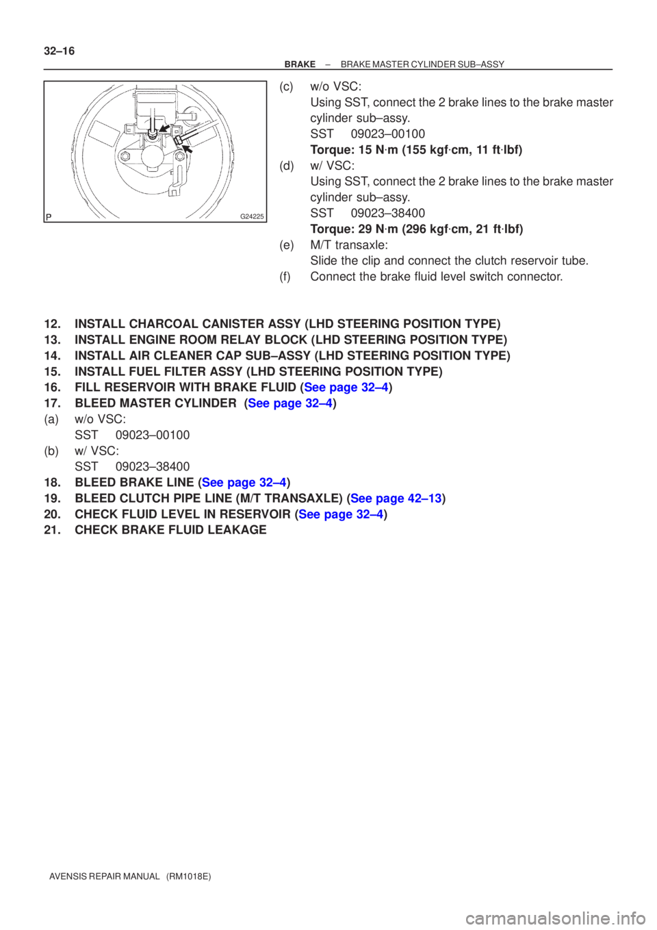
(c) w/o VSC: Using SST, connect the 2 brake lines to the brake master
cylinder sub±assy.
SST 09023±00100
Torque: 15 N �m (155 kgf �cm, 11 ft �lbf)
(d) w/ VSC: Using SST, connect the 2 brake lines to the brake master
cylinder sub±assy.
SST 09023±38400
Torque: 29 N �m (296 kgf �cm, 21 ft �lbf)
(e) M/T transaxle: Slide the clip and connect the clutch reservoir tube.
(f) Connect the brake fluid level switch connector.
12. INSTALL CHARCOAL CANISTER ASSY (LHD STEERING POSITION TYPE)
13. INSTALL ENGINE ROOM RELAY BLOCK (LHD STEERING POSITION TYPE)
14. INSTALL AIR CLEANER CAP SUB±ASSY (LHD STEERING POSITION TYPE)
15. INSTALL FUEL FILTER ASSY (LHD STEERING POSITION TYPE)
16.FILL RESERVOIR WITH BRAKE FLUID (See page 32±4)
17.BLEED MASTER CYLINDER (See page 32±4)
(a) w/o VSC: SST 09023±00100
(b) w/ VSC: SST 09023±38400
18.BLEED BRAKE LINE (See page 32±4)
19.BLEED CLUTCH PIPE LINE (M/T TRANSAXLE) (See page 42±13)
20.CHECK FLUID LEVEL IN RESERVOIR (See page 32±4)
21. CHECK BRAKE FLUID LEAKAGE
Page 2586 of 5135
320W5±01
G24285
LHD Steering Position Type:
Charcoal Canister Assy
Brake Fluid Level
Switch Connector
Clutch Reservoir
Tube M/T Transaxle:Brake Booster Assy
Clip
Way
20 (204, 15)
15 (155, 11)
15 (155, 11)*1
29 (296, 21)*2
15 (155, 11)*1
29 (296, 21)*2
Brake Master
Cylinder Sub±assy
20 (204, 15)
Engin Room Relay Block
RHD Steering Position Type:Air Cleaner Cap Sub±assy
Brake Fluid Level
Switch ConnectorBrake Master
Cylinder Sub±assy
Clip
Accelerator Control
Cable Support
20 (204, 15)
*1
w/ ABS:*2 w/ VSC:N�m (kgf�cm, ft�lbf) : Specified torque
15 (155, 11)*1
29 (296, 21)*2
15 (155, 11)*1
29 (296, 21)*2
Clutch Reservoir
Tube M/T Transaxle:
Brake Booster Assy
5.4 (55, 48 in.�lbf)
Fuel Filter Assy Diesel Engin Type:
± BRAKEBRAKE MASTER CYLINDER SUB±ASSY
32±11
AVENSIS REPAIR MANUAL (RM1018E)
BRAKE MASTER CYLINDER SUB±ASSY
COMPONENTS
Page 2658 of 5135
330C7±01
F44818
33±10
±
PARKING BRAKE PARKING BRAKE CABLE ASSY NO.3
AVENSIS REPAIR MANUAL (RM1018E)
REPLACEMENT
HINT:
For parking brake cable assy No.2, perform the same procedure to the RH sid\
e.
1. REMOVE REAR WHEEL
2.DISCONNECT REAR DISC BRAKE CALIPER ASSY LH (See page 30±31)
3.REMOVE REAR DISC(See page 33±14)
4.REMOVE PARKING BRAKE ADJUSTER KIT (See page 33±14)
5.REMOVE PARKING BRAKE SHOE ADJUSTING SCREW SET(See page 33±14)
6.REMOVE PARKING BRAKE SHOE KIT (See page 33±14) SST 09718±00010
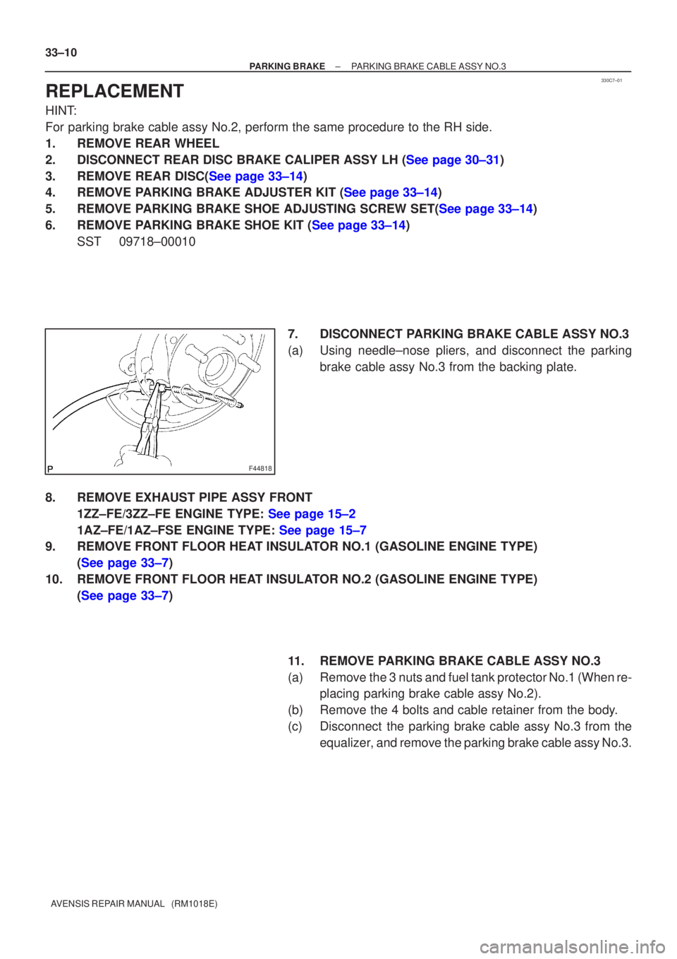
7. DISCONNECT PARKING BRAKE CABLE ASSY NO.3
(a) Using needle±nose pliers, and disconnect the parkingbrake cable assy No.3 from the backing plate.
8. REMOVE EXHAUST PIPE ASSY FRONT 1ZZ±FE/3ZZ±FE ENGINE TYPE: See page 15±2
1AZ±FE/1AZ±FSE ENGINE TYPE: See page 15±7
9. REMOVE FRONT FLOOR HEAT INSULATOR NO.1 (GASOLINE ENGINE TYPE)
(See page 33±7)
10. REMOVE FRONT FLOOR HEAT INSULATOR NO.2 (GASOLINE ENGINE TYPE) (See page 33±7)
11. REMOVE PARKING BRAKE CABLE ASSY NO.3
(a) Remove the 3 nuts and fuel tank protector No.1 (When re-placing parking brake cable assy No.2).
(b) Remove the 4 bolts and cable retainer from the body.
(c) Disconnect the parking brake cable assy No.3 from the equalizer, and remove the parking brake cable assy No.3.