Page 2287 of 5135

AVENSIS REPAIR MANUAL (RM1018E)
57.REMOVE INJECTION PIPE SUB±ASSY NO.4 SST0902")
A09656
A79144
A09566
1
234 5
67 89
1011
12 13
1415
16
1718
14±334
±
ENGINE MECHANICAL CYLINDER HEAD GASKET(1CD±FTV)
AVENSIS REPAIR MANUAL (RM1018E)
57.REMOVE INJECTION PIPE SUB±ASSY NO.4 SST09023±12700
HINT:
Perform the same procedures as injection pipe No. 1.
58.REMOVE VACUUM PUMP ASSY (See page 14±318)
59. REMOVE NOZZLE HOLDER SEAL
(a) Using a screwdriver, pry out the 4 nozzle holder seals.
60. REMOVE CYLINDER HEAD COVER SUB±ASSY
(a) Remove the 10 bolts, the cylinder head cover and thegasket.
61.REMOVE NOZZLE LEAKAGE PIPE ASSY(See page 11±60)
62.REMOVE INJECTOR ASSY(See page 11±60)
HINT:
Since each injector assembly has a characteristic fuel injecting behavior, store them in correct order so that
they can be returned to the original locations when re±assembling.
63.REMOVE CAMSHAFT OIL SEAL RETAINER (See page 14±318)
64.REMOVE NO.2 CAMSHAFT (See page 14±318)
65.REMOVE CAMSHAFT (See page 14±318) 66. REMOVE CYLINDER HEAD SUB±ASSY
(a) Using several steps, loosen the 18 cylinder head boltsuniformly in the sequence shown in the illustration. Re-
move the 18 cylinder head bolts and the plate washers.
NOTICE:
Cylinder head warpage or cracking could result from re-
moving bolts in incorrect order.
Page 2293 of 5135

AVENSIS REPAIR MANUAL (RM1018E)
88.INSTALL FUEL INLET PIPE SUB±ASSY
NOTICE:
�In case of having the cylinder head ga")
A79148
SST
A79149
SST
14±340
±
ENGINE MECHANICAL CYLINDER HEAD GASKET(1CD±FTV)
AVENSIS REPAIR MANUAL (RM1018E)
88.INSTALL FUEL INLET PIPE SUB±ASSY
NOTICE:
�In case of having the cylinder head gasket replaced,
must replace fuel inlet pipe, too.
�When assembling the pipe, perform the operation
with the engine cold under room temperature.
(a)Temporarily install the new fuel inlet pipe.
(b)Using SST, tighten the nut of the fuel inlet pipe to the com- mon rail side.
SST09023±12700
Torque:
42 N�m (428 kgf �cm, 31 ft �lbf) for a used pipe using SST
46 N �m (469 kgf �cm, 34 ft �lbf) for a used pipe not using
SST
31 N �m (316 kgf �cm, 23 ft �lbf) for a new pipe using SST
34 N �m (347 kgf �cm, 25 ft �lbf) for a new pipe not using
SST
HINT:
�Use a torque wrench with a fulcrum length of 30 cm
(11.81 in.)
�Check if the used pipe has deflection or is installed prop-
erly after inlet pipe is reassembled. If there is deflection
or if it can not be installed properly, replace the used pipe
with a new pipe.
(c)Using SST, tighten the nut of the fuel inlet pipe to the pump side.
SST09023±12700
Torque:
42 N�m (428 kgf �cm, 31 ft �lbf) for a used pipe using SST
46 N �m (469 kgf �cm, 34 ft �lbf) for a used pipe not using
SST
31 N �m (316 kgf �cm, 23 ft �lbf) for a new pipe using SST
34 N �m (347 kgf �cm, 25 ft �lbf) for a new pipe not using
SST
HINT:
�Use a torque wrench with a fulcrum length of 30 cm
(11.81 in.)
�Check if the used pipe has deflection or is installed prop-
erly after inlet pipe is reassembled. If there is deflection
or if it can not be installed properly, replace the used pipe
with a new pipe.
89.INSTALL TURBOCHARGER SUB±ASSY (See page 13±11)
90.INSTALL TURBO OIL INLET PIPE SUB±ASSY (See page 13±11)
91.INSTALL TURBOCHARGER STAY (See page 13±11)
92.INSTALL EXHAUST MANIFOLD CONVERTER SUB±ASSY (See page 13±11)
93.INSTALL MANIFOLD STAY NO.2 (See page 13±11)
94.INSTALL EXHAUST MANIFOLD HEAT INSULATOR NO.2 (See page 13±11)
Page 2294 of 5135

14±341
AVENSIS REPAIR MANUAL (RM1018E)
95.INSTALL TURBO INSULATOR NO.1 (See page 13±11)
96.INSTALL TURBO INSULATOR NO.2 (See page 13±11)
97.IN")
±
ENGINE MECHANICAL CYLINDER HEAD GASKET (1CD±FTV)
14±341
AVENSIS REPAIR MANUAL (RM1018E)
95.INSTALL TURBO INSULATOR NO.1 (See page 13±11)
96.INSTALL TURBO INSULATOR NO.2 (See page 13±11)
97.INSTALL EXHAUST PIPE ASSY (W/ COLD AREA) (See page 13±11)
98.INSTALL EXHAUST PIPE ASSY FRONT(See page 15±10)
99.INSTALL FLOOR PANEL BRACE FRONT(See page 15±10)
100.INSTALL HEATER BRACKET (W/ COLD AREA)(See page 13±11)
101.INSTALL HEATER PUMP ASSY (W/ COLD AREA)(See page 13±11)
102.INSTALL FUEL FILTER ASSY(See page 11±82)
103.SET NO. 1 CYLINDER TO TDC/COMPRESSION(See page 14±307)
SST 09960±10010 (09962±01000, 09963±01000)
104.INSTALL TIMING BELT(See page 14±307)
105.CHECK VALVE TIMING(See page 14±307)
106.TIMING CHAIN COVER PLATE(See page 14±307)
107.INSTALL TRANSVERSE ENGINE ENGINE MOUNTING BRACKET(See page 14±307)
108.INSTALL TIMING BELT GUIDE(See page 14±307)
109.INSTALL TIMING BELT NO.1 COVER(See page 14±307)
110.INSTALL TIMING BELT NO.2 COVER(See page 14±307)
111.INSTALL IDLER PULLEY SUB±ASSY(See page 14±307)
112.INSTALL CRANKSHAFT PULLEY(See page 14±307) SST 09213±54015 (90105±08076), 09330±00021
113.INSTALL ENGINE MOUNTING INSULATOR SUB±ASSY RH(See page 14±307)
114.INSTALL POWER STEERING IDLE PULLEY BRACKET(See page 14±307)
115. ADJUST V (COOLER COMPRESSOR TO CRANKSHAFT PULLEY) BELT NO.1 (See page 14±269)
116.INSTALL INJECTOR DRIVER (See page 14±286)
117.INSTALL AIR TUBE NO.1(See page 14±270)
118.INSTALL AIR TUBE NO.2 (See page 14±286)
119.INSTALL AIR CLEANER ASSY (See page 14±286)
120.INSTALL VACUUM RESERVOIR SUB±ASSY (See page 13±11)
121. INSTALL ENGINE COVER NO.1
Torque: 8.0 N �m (82 kgf �cm, 71 in. �lbf)
122. INSTALL FRONT WHEEL RH Torque: 103 N �m (1,050 kgf �cm, 76 ft �lbf)
123. ADD ENGINE OIL
124.ADD ENGINE COOLANT(See page 16±44)
125.CHECK FOR FUEL LEAKS(See page 11±60)
126. CHECK FOR ENGINE OIL LEAKS
127.CHECK FOR ENGINE COOLANT LEAKS(See page 16±44)
128. CHECK FOR EXHAUST GAS LEAKS
Page 2296 of 5135
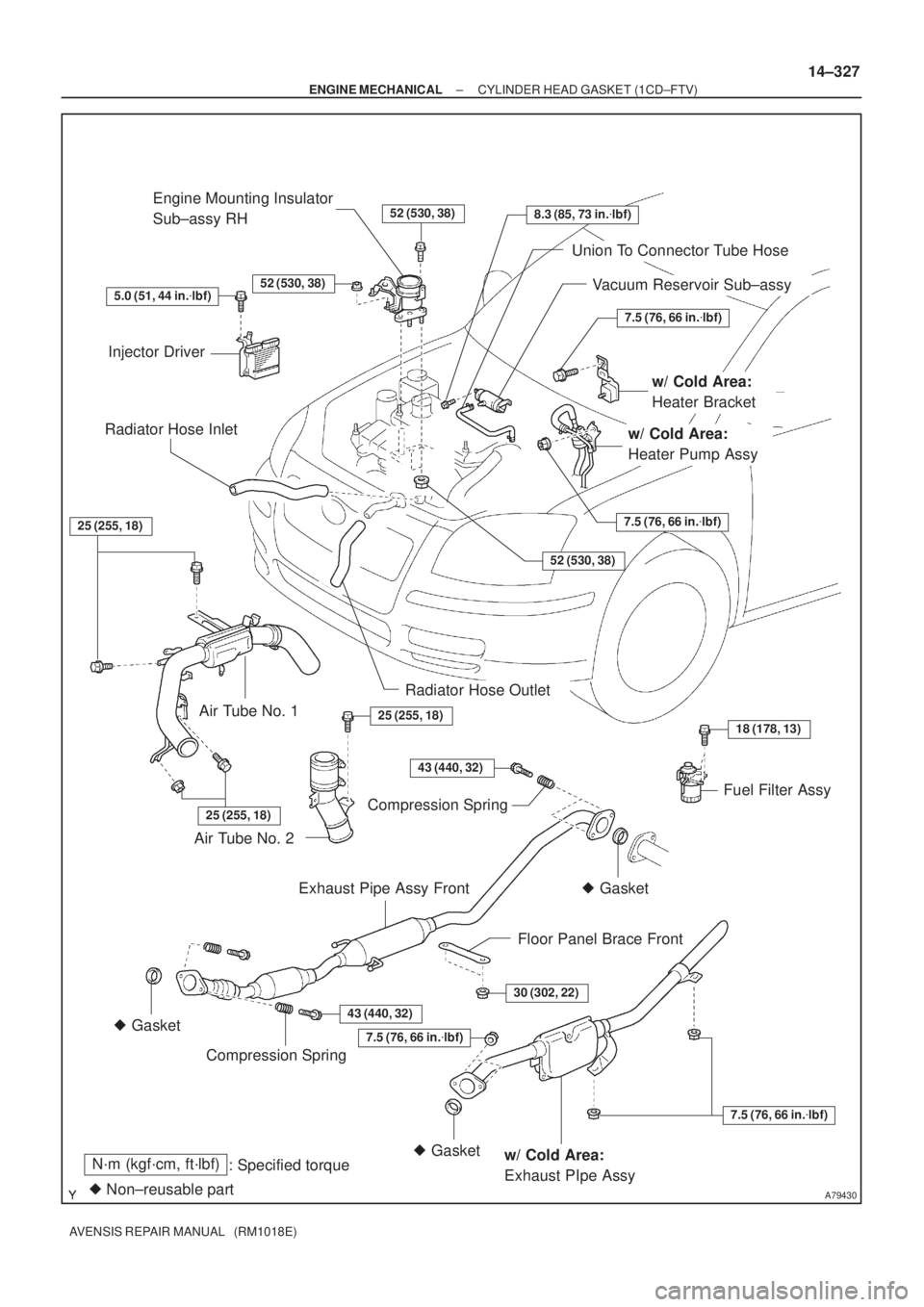
A79430
N´m (kgf´cm, ft´lbf)
: Specified torque
� Non±reusable part
52 (530, 38)
52 (530, 38)
7.5 (76, 66 in.�lbf)
7.5 (76, 66 in.�lbf)
52 (530, 38)
25 (255, 18)
25 (255, 18)
43 (440, 32)
18 (178, 13)
30 (302, 22)
7.5 (76, 66 in.�lbf)
7.5 (76, 66 in.�lbf)
43 (440, 32)� Gasket
� Gasket� Gasket
Injector DriverEngine Mounting Insulator
Sub±assy RH
Vacuum Reservoir Sub±assy
w/ Cold Area:
Heater Bracket
Radiator Hose Inlet
Radiator Hose Outlet
Fuel Filter Assy Air Tube No. 1
Air Tube No. 2
Exhaust Pipe Assy Front
Floor Panel Brace Front
w/ Cold Area:
Exhaust PIpe Assy
Union To Connector Tube Hose
w/ Cold Area:
Heater Pump Assy
Compression Spring
Compression Spring
8.3 (85, 73 in.�lbf)
25 (255, 18)
5.0 (51, 44 in.�lbf)
± ENGINE MECHANICALCYLINDER HEAD GASKET (1CD±FTV)
14±327
AVENSIS REPAIR MANUAL (RM1018E)
Page 2299 of 5135
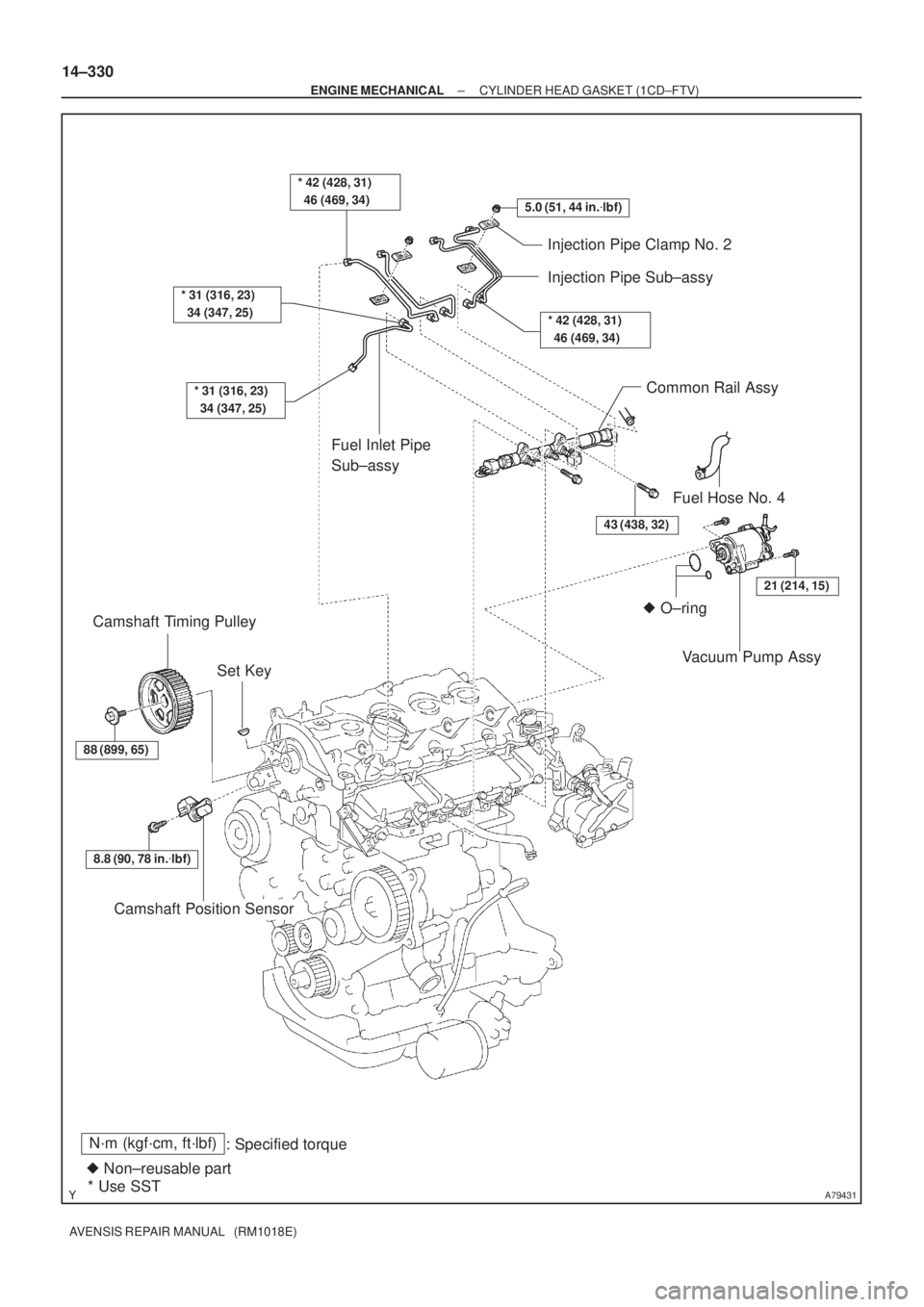
A79431
N´m (kgf´cm, ft´lbf)
: Specified torque
� Non±reusable part
* Use SST
5.0 (51, 44 in.�lbf)
* 31 (316, 23)
34 (347, 25)
* 31 (316, 23)
34 (347, 25)
Injection Pipe Clamp No. 2
Injection Pipe Sub±assy
* 42 (428, 31)
46 (469, 34)
Fuel Inlet Pipe
Sub±assy
� O±ring
43 (438, 32)
21 (214, 15)
Common Rail Assy
Fuel Hose No. 4
Camshaft Position Sensor
Set Key Camshaft Timing Pulley
88 (899, 65)
Vacuum Pump Assy
8.8 (90, 78 in.�lbf)
* 42 (428, 31)
46 (469, 34)
14±330
± ENGINE MECHANICALCYLINDER HEAD GASKET (1CD±FTV)
AVENSIS REPAIR MANUAL (RM1018E)
Page 2300 of 5135
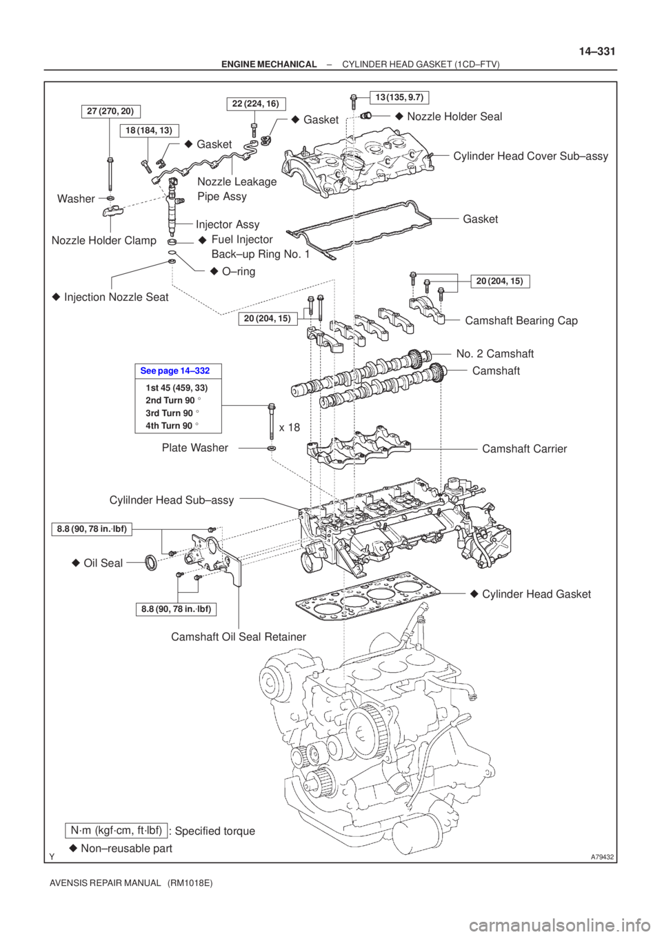
A79432
N´m (kgf´cm, ft´lbf): Specified torque
� Non±reusable part �
Gasket
18 (184, 13)
27 (270, 20)22 (224, 16)13 (135, 9.7)
� Gasket
� O±ring
Fuel Injector
Back±up Ring No. 1
�
� Injection Nozzle Seat
20 (204, 15)
8.8 (90, 78 in. �lbf)
� Oil Seal
8.8 (90, 78 in. �lbf)
1st 45 (459, 33)
2nd Turn 90 �
3rd Turn 90 �
4th Turn 90 �
See page 14±332
20 (204, 15)
Washer
Nozzle Holder Clamp Nozzle Leakage
Pipe Assy
Injector Assy �
Nozzle Holder Seal
Cylinder Head Cover Sub±assy
Gasket
Camshaft Bearing Cap
No. 2 Camshaft Camshaft
Camshaft Carrier
� Cylinder Head Gasket
Camshaft Oil Seal Retainer
Cylilnder Head Sub±assy
Plate Washer
x 18
±
ENGINE MECHANICAL CYLINDER HEAD GASKET (1CD±FTV)
14±331
AVENSIS REPAIR MANUAL (RM1018E)
Page 2302 of 5135

14±319
AVENSIS REPAIR MANUAL (RM1018E)
26.REMOVE INJECTION PIPE SUB±ASSY NO.1
(See page 11±60)
(a) Remove the 2 nuts and 2 upper i")
A79143
SST
A09656
A79144
±
ENGINE MECHANICAL CAMSHAFT(1CD±FTV)
14±319
AVENSIS REPAIR MANUAL (RM1018E)
26.REMOVE INJECTION PIPE SUB±ASSY NO.1
(See page 11±60)
(a) Remove the 2 nuts and 2 upper infection pipe clamps
from the intake manifold.
(b) Using SST, remove the injection pipe from the common rail side.
SST 09023±12700
(c) Using SST, remove the injection pipe from the injector side.
SST 09023±12700
(d) After removing the fuel pipe, to prevent dust or foreign ob- jects from being introduced, cover the common rail with
vinyl tape and protect the injector inlet with a vinyl or a
plastic bag.
27.REMOVE INJECTION PIPE SUB±ASSY NO.2(See page 11±60) SST 09023±12700
HINT:
Perform the same procedures as injection pipe No. 1.
28.REMOVE INJECTION PIPE SUB±ASSY NO.3(See page 11±60) SST 09023±12700
HINT:
Perform the same procedures as injection pipe No. 1.
29.REMOVE INJECTION PIPE SUB±ASSY NO.4(See page 11±60) SST 09023±12700
HINT:
Perform the same procedures as injection pipe No. 1.
30. REMOVE VACUUM PUMP ASSY
(a) Remove vacuum hose.
(b) Remove vacuum pump oil hose.
(c) Remove the 2 bolts and the vacuum pump assembly.
31. REMOVE NOZZLE HOLDER SEAL
(a) Using a screwdriver, pry out the 4 nozzle holder seals.
32. REMOVE CYLINDER HEAD COVER SUB±ASSY
(a) Remove the 10 bolts, the cylinder head cover and thegasket.
Page 2303 of 5135

AVENSIS REPAIR MANUAL (RM1018E)
33.REMOVE NOZZLE LEAKAGE PIPE ASSY (See page 11±60")
A09668
A09650
5
6
4 2
1
12 3
1011
13
8
7
15
14
9
A09619
SST
A09620
14±320
±
ENGINE MECHANICAL CAMSHAFT(1CD±FTV)
AVENSIS REPAIR MANUAL (RM1018E)
33.REMOVE NOZZLE LEAKAGE PIPE ASSY (See page 11±60)
34.REMOVE INJECTOR ASSY (See page 11±60)
HINT:
Since each injector assembly has a characteristic fuel injecting behavior, store them in correct order so that
they can be returned to the original locations when re±assembling. 35. REMOVE CAMSHAFT OIL SEAL RETAINER
(a) Remove the 4 bolts.
(b) Using a screwdriver, remove the oil seal retainer by pryingbetween the oil seal retainer and the camshaft bearing
cap.
36. REMOVE CAMSHAFT
(a) Using several steps, loosen and remove the 15 bearing cap bolts uniformly in the sequence shown in the illustra-
tion.
(b) Remove the 5 bearing caps and the camshaft sub±assy.
37. REMOVE NO.2 CAMSHAFT
(a) Remove the camshaft sub±assy and the camshaft carrier. 38. REMOVE CAMSHAFT OIL SEAL
(a) Using a screwdriver and a hammer, tap out the oil seal.
39. INSTALL CAMSHAFT OIL SEAL
(a) Using SST and a hammer, tap in a new oil seal until its sur-face is flush with the camshaft oil seal retainer edge.
SST 09223±46011