Page 2231 of 5135
±
ENGINE MECHANICAL VALVE CLEARANCE(1AZ±FSE)
14±191
AVENSIS REPAIR MANUAL (RM1018E)
(h)Install the camshafts. (See page 14±240)
(i)Install the chain tensioner. (See page 14±240)
14.INSTALL CYLINDER HEAD COVER SUB±ASSY (See page 14±240)
15.INSTALL IGNITION COIL ASSY
Torque: 9.0 N �m (92 kgf �cm,80 in. �lbf)
16.INSTALL FUEL PIPE SUB±ASSY NO.1 (See page 11±52) SST09023±12900
17.INSTALL FUEL TUBE SUB±ASSY (See page 11±33)
18.INSTALL FUEL PRESSURE PULSATION DAMPER ASSY (See page 11±52)
19.CHECK FOR ENGINE OIL LEAKS
20.CHECK FOR FUEL LEAKS (
See page 11±33)
21. INSTALL ENGINE COVER SUB±ASSY NO.1 Torque: 7.0 N �m (71 kgf �cm, 62 in. �lbf)
Page 2234 of 5135
A79418N´m (kgf´cm, ft´lbf)
: Specified torque
25 (255, 18)
18 (178, 13)
Injector Driver
Air Tube No. 2Union To Connector Tube Hose
Fuel Filter AssyHeater Inlet Water Hose Heater Outlet Water Hose Vacuum Reservoir Sub±assy
8.3 (85, 73 in.�lbf)
5.0 (51, 44 in.�lbf)
14±278
± ENGINE MECHANICALPARTIAL ENGINE ASSY (1CD±FTV)
AVENSIS REPAIR MANUAL (RM1018E)
Page 2240 of 5135

: Specified torque
� Non±reusable part� Gasket
� O±ring
* Use SST� Gasket � Gasket
� Gasket
� Gasket
� Gasket3.6 to 6.9 (40 to 70, 35 to 61 in.�lbf)
5.0 (51, 44 in.�lb")
A79423
N´m (kgf´cm, ft´lbf)
: Specified torque
� Non±reusable part� Gasket
� O±ring
* Use SST� Gasket � Gasket
� Gasket
� Gasket
� Gasket3.6 to 6.9 (40 to 70, 35 to 61 in.�lbf)
5.0 (51, 44 in.�lbf)
7.4 (76, 66 in.�lbf)
* 31 (316, 23)
34 (347, 25)
43 (438, 32)
21 (214, 15)
18 (184, 13)
21 (214, 15)
21 (214, 15)
21 (214, 15)
64 (650, 47)
21 (214, 15)
* 31 (316, 23)
34 (347, 25)
* 31 (316, 23)
34 (347, 25)
Injection Pipe Clamp No. 2
� Injection Pipe Sub±assy
* 31 (316, 23)
34 (347, 25)
Common Rail Assy
Fuel Hose No. 4
Vacuum Pump Assy
Nozzle Leakage Pipe No. 2Fuel Inlet Pipe Sub±assy
EGR Valve Assy
Water Outlet Sub±assy
Engine Coolant
Temperature Sensor
Intake Air Connector Sub±assy
Intake Manifold
Wiring Harness Clamp Bracket Injection Pump
Drive Pulley Timing Belt
No. 3 CoverSeal Washer Camshaft Position Sensor
Check Valve
8.8 (90, 78 in.�lbf)
8.8 (90, 78 in.�lbf)
21 (214, 15)
21 (214, 15)
14±284
± ENGINE MECHANICALPARTIAL ENGINE ASSY (1CD±FTV)
AVENSIS REPAIR MANUAL (RM1018E)
Page 2241 of 5135
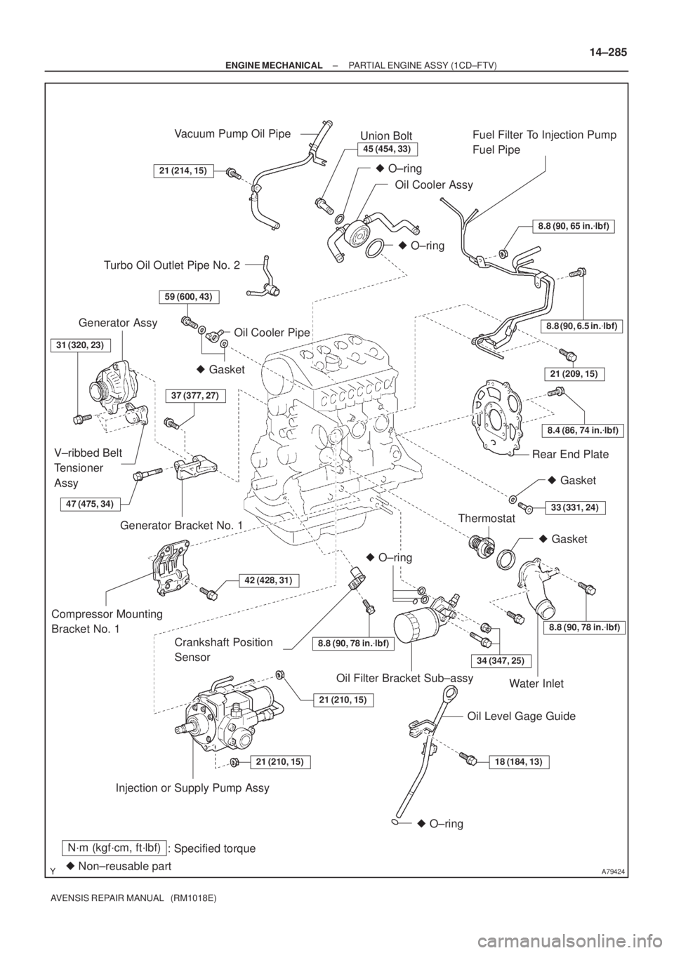
A79424
N´m (kgf´cm, ft´lbf)
: Specified torque
� Non±reusable part
8.8 (90, 65 in.�lbf)
8.8 (90, 6.5 in.�lbf)
8.4 (86, 74 in.�lbf)
21 (209, 15)
8.8 (90, 78 in.�lbf)
34 (347, 25)
18 (184, 13)21 (210, 15)
21 (210, 15)
42 (428, 31)
37 (377, 27)
59 (600, 43)
21 (214, 15)
45 (454, 33)
� O±ring
� O±ring
� Gasket
� O±ring
� O±ring
Vacuum Pump Oil Pipe
Union Bolt
Oil Cooler AssyFuel Filter To Injection Pump
Fuel Pipe
Rear End Plate
Crankshaft Position
Sensor
Thermostat
Water Inlet
Oil Level Gage Guide Oil Filter Bracket Sub±assy
Injection or Supply Pump Assy Compressor Mounting
Bracket No. 1Generator Bracket No. 1 V±ribbed Belt
Tensioner
AssyGenerator Assy
Oil Cooler Pipe
� Gasket
Turbo Oil Outlet Pipe No. 2
31 (320, 23)
� Gasket
33 (331, 24)
8.8 (90, 78 in.�lbf)
47 (475, 34)
± ENGINE MECHANICALPARTIAL ENGINE ASSY (1CD±FTV)
14±285
AVENSIS REPAIR MANUAL (RM1018E)
Page 2242 of 5135

AVENSIS REPAIR MANUAL (RM1018E)
VALVE CLEARANCE(1CD±FTV)
ADJUSTMENT
NOTICE:
�Before removing the injection pipes,")
141C2±01
A78277
A79143
SST
14±270
±
ENGINE MECHANICAL VALVE CLEARANCE(1CD±FTV)
AVENSIS REPAIR MANUAL (RM1018E)
VALVE CLEARANCE(1CD±FTV)
ADJUSTMENT
NOTICE:
�Before removing the injection pipes, clean them up with a soft brush and compr\
essed air.
�After removing the injection pipe, cover the supply pump, the common rail and the injector
mounting area of the cylinder head cover with vinyl tape to prevent dust from being introduce\
d.
�After removing the cylinder head cover, protect the injector inlet with a vinyl or a plastic bag
to prevent foreign objects from being introduced.
HINT:
Inspect and adjust the valve clearance when the engine is cold.
1.REMOVE RADIATOR SUPPORT OPENING COVER
2.REMOVE FRONT WHEEL RH
3.REMOVE ENGINE UNDER COVER RH
4.DRAIN ENGINE COOLANT (See page 16±44)
5.REMOVE ENGINE COVER NO.1
(a)Remove the 5 nuts and the engine cover.
6.REMOVE AIR TUBE NO.1
(a)Disconnect the vacuum hoses and the connectors.
(b)Loosen the hose clamps.
(c)Remove the 3 bolts and nut, and then detach the air tubeNo. 1.
7.REMOVE TIMING BELT NO.2 COVER (See page 14±307) 8. REMOVE INJECTION PIPE SUB±ASSY NO.1
(a) Remove the 2 nuts and 2 upper infection pipe clampsfrom the intake manifold.
(b) Using SST, remove the injection pipe from the common rail side.
SST 09023±12700
(c) Using SST, remove the injection pipe from the injector
side.
SST 09023±12700
(d) After removing the fuel pipe, to prevent dust or foreign ob- jects from being introduced, cover the common rail with
vinyl tape and protect the injector inlet with a vinyl or a
plastic bag.
Page 2243 of 5135

14±271
AVENSIS REPAIR MANUAL (RM1018E)
9.REMOVE INJECTION P")
A09687
UpwardCam Lobe
Clearance
A80107
A81553
Upward
Notch
Cam Lobe
Intake
Manifold
Side
±
ENGINE MECHANICAL VALVE CLEARANCE(1CD±FTV)
14±271
AVENSIS REPAIR MANUAL (RM1018E)
9.REMOVE INJECTION PIPE SUB±ASSY NO.2
SST09023±12700
HINT:
Perform the same procedures as injection pipe No. 1.
10.REMOVE INJECTION PIPE SUB±ASSY NO.3
SST09023±12700
HINT:
Perform the same procedures as injection pipe No. 1.
11.REMOVE INJECTION PIPE SUB±ASSY NO.4
SST09023±12700
HINT:
Perform the same procedures as injection pipe No. 1.
12.REMOVE CYLINDER HEAD COVER SUB±ASSY (See page 11±60)
13.REMOVE NOZZLE LEAKAGE PIPE ASSY (See page 11±60)
14.REMOVE INJECTOR ASSY (See page 11±60)
HINT:
Since each injector assembly has characteristic fuel injecting behavior, store them in correct order so that
they can be returned to the original locations when re±assembling.
15. INSPECT VALVE CLEARANCE
(a) Turn the crankshaft so that the cam lobe located over theinspecting valve faces upward.
(b) Using a feeler gauge, measure the clearance between the valve lifter and the camshaft.
(c) Measure the clearance at 16 places.
(d) Record the out±of specification valve clearance mea- surements. They will be used later to determine the re-
quired replacement adjusting shim.
Valve clearance (Cold):
Intake0.20 to 0.30 mm (0.008 to 0.012 in.)
Exhaust0.35 to 0.45 mm (0.014 to 0.018 in.)
16. ADJUST VALVE CLEARANCE
(a) Remove the adjusting shim.(1) Turn the crankshaft so that the cam lobe located
over the adjusting valve faces upward.
(2) Position the notch of the valve lifter toward the in- take manifold side.
Page 2246 of 5135

AVENSIS REPAIR MANUAL (RM1018E)
(d)Using SST, tighten the nut of the injection pipe to the injec- tor side.
SST09023±12700
Torque:
42 N�m (42")
14±274
±
ENGINE MECHANICAL VALVE CLEARANCE(1CD±FTV)
AVENSIS REPAIR MANUAL (RM1018E)
(d)Using SST, tighten the nut of the injection pipe to the injec- tor side.
SST09023±12700
Torque:
42 N�m (428 kgf �cm, 31 ft �lbf) for a used pipe using SST
46 N �m (469 kgf �cm, 34 ft �lbf) for a used pipe not using
SST
31 N �m (316 kgf �cm, 23 ft �lbf) for a new pipe using SST
34 N �m (347 kgf �cm, 25 ft �lbf) for a new pipe not using
SST
HINT:
�Use a torque wrench with a fulcrum length of 30 cm
(11.81 in.)
�Check if the used pipe has deflection or is installed prop-
erly after injection pipe is reassembled. If there is deflec-
tion or if it can not be installed properly, replace the used
pipe with a new pipe.
(e)Install the 2 upper injection pipe clamps with the 2 nuts. Torque: 5.0 N �m (51 kgf �cm, 44 in. �lbf)
21.INSTALL INJECTION PIPE SUB±ASSY NO.2
SST09023±12700
HINT:
Perform the same procedures as injection pipe No. 1.
22.INSTALL INJECTION PIPE SUB±ASSY NO.3 SST09023±12700
HINT:
Perform the same procedures as injection pipe No. 1.
23.INSTALL INJECTION PIPE SUB±ASSY NO.4 SST09023±12700
HINT:
Perform the same procedures as injection pipe No. 1.
24.INSTALL TIMING BELT NO.2 COVER (See page 11±60)
25. INSTALL AIR TUBE NO.1 Torque: 25 N �m (255 kgf �cm, 18 ft �lbf)
26. INSTALL ENGINE COVER NO.1 Torque: 8.0 N �m (82 kgf �cm, 71 in. �lbf)
27. INSTALL FRONT WHEEL RH Torque: 103 N �m (1,050 kgf �cm, 76 ft �lbf)
28.ADD ENGINE COOLANT (See page 16±44)
29.CHECK FOR ENGINE COOLANT LEAKS (See page 16±44)
30.CHECK FOR FUEL LEAKS (See page 11±60)
Page 2256 of 5135

AVENSIS REPAIR MANUAL (RM1018E)
REPLACEMENT
1.DISCHARGE FUEL SYSTEM PRESSURE (See page 11±15)
2.REMOVE FRONT WHEE")
141BO±01
A77339
A77292
14±254
±
ENGINE MECHANICAL CYLINDER HEAD GASKET(1AZ±FSE)
AVENSIS REPAIR MANUAL (RM1018E)
REPLACEMENT
1.DISCHARGE FUEL SYSTEM PRESSURE (See page 11±15)
2.REMOVE FRONT WHEEL RH
3.REMOVE RADIATOR SUPPORT OPENING COVER
4.REMOVE ENGINE ROOM COVER SIDE
5.REMOVE ENGINE UNDER COVER RH
6.REMOVE ENGINE UNDER COVER LH
7.DRAIN COOLANT (See page 16±19)
8.DRAIN ENGINE OIL
(a)Install a new gasket and the drain plug after draining engine oil. Torque: 25 N �m (255 kgf �cm,18 ft �lbf)
9.REMOVE ENGINE COVER SUB±ASSY NO.1
(a)Remove the 2 nuts and the engine cover No. 1.
10.REMOVE FUEL PRESSURE PULSATION DAMPER ASSY
11.SEPARATE FUEL TUBE SUB±ASSY (See page 11±33)
12.REMOVE FUEL PIPE SUB±ASSY NO.1 (See page 11±52) SST 09023±12900
13.REMOVE FUEL PUMP ASSY (See page 11±52)
14.REMOVE FAN AND GENERATOR V BELT (See page 14±185) SST 09249±63010
15.REMOVE GENERATOR ASSY (See page 19±20)
16.REMOVE EXHAUST PIPE ASSY FRONT (See page 15±7)
17. SEPARATE VANE PUMP ASSY
(a) Remove the 2 bolts and separate the vane pump.
18. REMOVE IGNITION COIL ASSY
(a) Remove the 4 bolts and 4 ignition coils.

14±191
AVENSIS REPAIR MANUAL (RM1018E)
(h)Install the camshafts. (See page 14±240)
(i)Install the chain tensioner. (See page 14±240)
14.INSTALL CYLI")

: Specified torque
25 (255, 18)
18 (178, 13)
Injector Driver
Air Tube No. 2Union To Connector Tube Hose
Fuel Filter AssyHeater Inlet Water Hose Heater Outlet Water Hose V")