Page 2659 of 5135
F44819
F44820
±
PARKING BRAKE PARKING BRAKE CABLE ASSY NO.3
33±11
AVENSIS REPAIR MANUAL (RM1018E)
12. INSTALL PARKING BRAKE CABLE ASSY NO.3
(a) Connect the parking brake cable assy No.3 to the equaliz-
er.
(b) Install the parking brake cable assy No.3 with the 4 bolts. Torque: 5.0 N �m (55 kgf �cm, 48 in. �lbf)
(c) Install the fuel tank protector No.1 and 3 nuts (When re- placing parking brake cable assy No.2).
Torque: 5.5 N �m (56 kgf �cm, 49 in. �lbf)
13. INSTALL FRONT FLOOR HEAT INSULATOR NO.2 (GASOLINE ENGINE TYPE) (See page 33±7)
14. INSTALL FRONT FLOOR HEAT INSULATOR NO.1 (GASOLINE ENGINE TYPE) (See page 33±7)
15. INSTALL EXHAUST PIPE ASSY FRONT 1ZZ±FE/3ZZ±FE ENGINE TYPE: See page 15±2
1AZ±FE/1AZ±FSE ENGINE TYPE: See page 15±7
16. CONNECT PARKING BRAKE CABLE ASSY NO.3
(a) Connect the parking brake cable assy No.3 to the backingplate.
Page 2661 of 5135
3306C±05
F44817
Parking Brake Cable Assy No.2
Parking Brake Cable Assy No.3
Equalizer
Front Floor Heat
Insulator No.1Front Floor Heat Insulator No.2Fuel Tank Protector No.1
Exhaust Pipe SupportCable
Retainer
N�m (kgf�cm, ft�lbf) : Specified torqueFront Floor Panel Brace Gasoline Engine Type:Gasoline Engine Type:
5.5 (56, 49 in.�lbf)
5.0 (51, 44 in.�lbf)
5.0 (51, 44 in.�lbf)
5.0 (51, 44 in.�lbf)
5.0 (51, 44 in.�lbf)
43 (440, 32)
5.5 (56, 49 in.�lbf)
Parking Brake Cable No.2 Clamp
Parking Brake Cable
No.2 Clamp
5.0 (51, 44 in.�lbf)
43 (440, 32)30 (302, 21)
Exhaust Pipe Assy Front
Exhaust Pipe Support
43 (440, 32)
5.5 (56, 49 in.�lbf)
5.5 (56, 49 in.�lbf)
5.0 (51, 44 in.�lbf)
± PARKING BRAKEPARKING BRAKE CABLE ASSY NO.3
33±9
AVENSIS REPAIR MANUAL (RM1018E)
PARKING BRAKE CABLE ASSY NO.3
COMPONENTS
Page 2840 of 5135

5507E±03
AC2810
AC2811
N11084
Wrong Okay
HI
LO HI LO
± HEATER & AIR CONDITIONERAIR CONDITIONING SYSTEM
55±1
AVENSIS REPAIR MANUAL (RM1018E)
AIR CONDITIONING SYSTEM
PRECAUTION
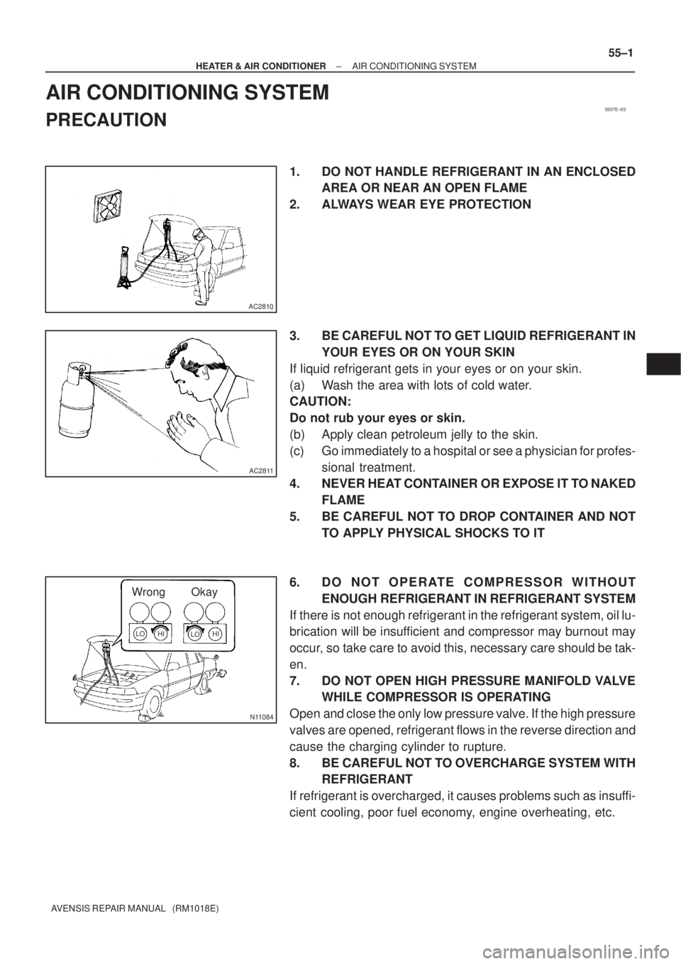
1. DO NOT HANDLE REFRIGERANT IN AN ENCLOSED
AREA OR NEAR AN OPEN FLAME
2. ALWAYS WEAR EYE PROTECTION
3. BE CAREFUL NOT TO GET LIQUID REFRIGERANT IN
YOUR EYES OR ON YOUR SKIN
If liquid refrigerant gets in your eyes or on your skin.
(a) Wash the area with lots of cold water.
CAUTION:
Do not rub your eyes or skin.
(b) Apply clean petroleum jelly to the skin.
(c) Go immediately to a hospital or see a physician for profes-
sional treatment.
4. NEVER HEAT CONTAINER OR EXPOSE IT TO NAKED
FLAME
5. BE CAREFUL NOT TO DROP CONTAINER AND NOT
TO APPLY PHYSICAL SHOCKS TO IT
6. DO NOT OPERATE COMPRESSOR WITHOUT
ENOUGH REFRIGERANT IN REFRIGERANT SYSTEM
If there is not enough refrigerant in the refrigerant system, oil lu-
brication will be insufficient and compressor may burnout may
occur, so take care to avoid this, necessary care should be tak-
en.
7. DO NOT OPEN HIGH PRESSURE MANIFOLD VALVE
WHILE COMPRESSOR IS OPERATING
Open and close the only low pressure valve. If the high pressure
valves are opened, refrigerant flows in the reverse direction and
cause the charging cylinder to rupture.
8. BE CAREFUL NOT TO OVERCHARGE SYSTEM WITH
REFRIGERANT
If refrigerant is overcharged, it causes problems such as insuffi-
cient cooling, poor fuel economy, engine overheating, etc.
Page 2922 of 5135

± HEATER & AIR CONDITIONERCOMBUSTION TYPE POWER HEATER SYSTEM
55±17
AVENSIS REPAIR MANUAL (RM1018E)
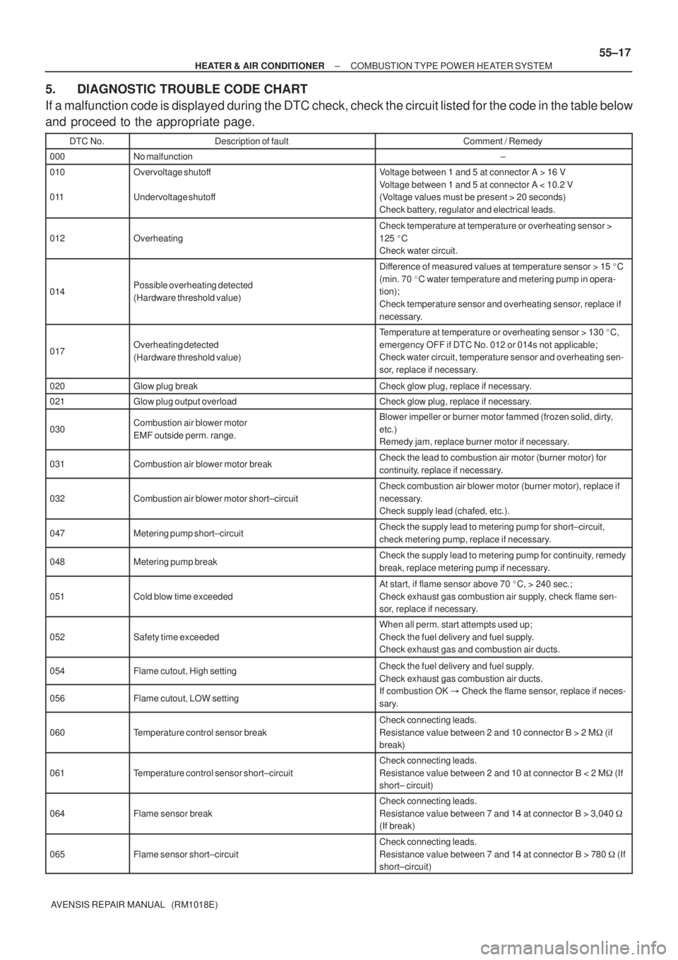
5. DIAGNOSTIC TROUBLE CODE CHART
If a malfunction code is displayed during the DTC check, check the circuit listed for the code in the table below
and proceed to the appropriate page.
DTC No.Description of faultComment / Remedy
000No malfunction±
010
011Overvoltage shutoff
Undervoltage shutoffVoltage between 1 and 5 at connector A > 16 V
Voltage between 1 and 5 at connector A < 10.2 V
(Voltage values must be present > 20 seconds)
Check battery, regulator and electrical leads.
012Overheating
Check temperature at temperature or overheating sensor >
125 �C
Check water circuit.
014Possible overheating detected
(Hardware threshold value)
Difference of measured values at temperature sensor > 15 �C
(min. 70 �C water temperature and metering pump in opera-
tion);
Check temperature sensor and overheating sensor, replace if
necessary.
017Overheating detected
(Hardware threshold value)
Temperature at temperature or overheating sensor > 130 �C,
emergency OFF if DTC No. 012 or 014s not applicable;
Check water circuit, temperature sensor and overheating sen-
sor, replace if necessary.
020Glow plug breakCheck glow plug, replace if necessary.
021Glow plug output overloadCheck glow plug, replace if necessary.
030Combustion air blower motor
EMF outside perm. range.Blower impeller or burner motor fammed (frozen solid, dirty,
etc.)
Remedy jam, replace burner motor if necessary.
031Combustion air blower motor breakCheck the lead to combustion air motor (burner motor) for
continuity, replace if necessary.
032Combustion air blower motor short±circuit
Check combustion air blower motor (burner motor), replace if
necessary.
Check supply lead (chafed, etc.).
047Metering pump short±circuitCheck the supply lead to metering pump for short±circuit,
check metering pump, replace if necessary.
048Metering pump breakCheck the supply lead to metering pump for continuity, remedy
break, replace metering pump if necessary.
051Cold blow time exceeded
At start, if flame sensor above 70 �C, > 240 sec.;
Check exhaust gas combustion air supply, check flame sen-
sor, replace if necessary.
052Safety time exceeded
When all perm. start attempts used up;
Check the fuel delivery and fuel supply.
Check exhaust gas and combustion air ducts.
054Flame cutout, High settingCheck the fuel delivery and fuel supply.
Check exhaust gas combustion air ducts.
056Flame cutout, LOW setting
Check exhaust gas combustion air ducts.
If combustion OK � Check the flame sensor, replace if neces-
sary.
060Temperature control sensor break
Check connecting leads.
Resistance value between 2 and 10 connector B > 2 M� (if
break)
061Temperature control sensor short±circuit
Check connecting leads.
Resistance value between 2 and 10 at connector B < 2 M� (If
short± circuit)
064Flame sensor break
Check connecting leads.
Resistance value between 7 and 14 at connector B > 3,040 �
(If break)
065Flame sensor short±circuit
Check connecting leads.
Resistance value between 7 and 14 at connector B > 780 � (If
short±circuit)
Page 2997 of 5135
550YS±01
I35345Claw
I35346
I35347
I35348
55±100
±
HEATER & AIR CONDITIONER HEATER ASSY
AVENSIS REPAIR MANUAL (RM1018E)
HEATER ASSY
REPLACEMENT
1.REMOVE AIR CLEANER ASSY (See page 11±82)
2.REMOVE FUEL FILTER ASSY (See page 11±82) 3. REMOVE AIR DUCT NO.3
(a) Release the claw fitting and remove the bolt and the en-gine room relay No.2 block.
(b) Remove the clip and the air duct No.3.
4. DISCONNECT HEATER INLET WATER HOSE
(a) Using pliers, grip the claws of the clip and slide the clip to disconnect the heater inlet water hose.
HINT:
Prepare a support plate and waste to catch the leaked coolant.
5. DISCONNECT HEATER WATER INLET HOSE A
(a) Using pliers, grip the claws of the clip and slide the clip to disconnect the heater inlet water hose A.
HINT:
Prepare a support plate and waste to catch the leaked coolant.
Page 2998 of 5135
I35349
I35350
I35350
I35349
±
HEATER & AIR CONDITIONER HEATER ASSY
55±101
AVENSIS REPAIR MANUAL (RM1018E)
6. REMOVE HEATER ASSY
(a) Using pliers, grip the claws of the clip and slide the clip to
disconnect the heater fuel hose.
HINT:
Prepare a support plate and waste to catch the leaked fuel.
(b) Disconnect the connector.
(c) Remove the 2 bolts and the heater assy.
7. INSTALL HEATER ASSY
(a) Install the heater assy with the 2 bolts. Torque: 7.5 N �m (76 kgf �cm, 66 in. �lbf)
(b) Connect the connector.
(c) Install the heater fuel hose.
HINT:
Prepare a support plate and waste to catch the leaked fuel.
8.INSTALL FUEL FILTER ASSY (See page 11±82)
9.INSTALL AIR CLEANER ASSY (See page 11±82)
10.ADD ENGINE COOLANT (See page 16±44)
11.CHECK FOR ENGINE COOLANT LEAKS (See page 16±37)
12.CHECK FUEL LEAK (See page 11±56)
Page 3106 of 5135

650SV±01
I33423
V LH LineV RH LineV Line
Ground
H Line
± LIGHTINGHEADLAMP UNIT LH
65±19
AVENSIS REPAIR MANUAL (RM1018E)
ADJUSTMENT
1. HEADLIGHT AIM ONLY
HINT:
�Perform aiming adjustment with Low±beam.
�Since the Low±beam light and the High±beam light is a
unit, if aiming on either side is connect, the other side
should also be connect.
However, check both beams just to make sure.
(a) Prepare vehicle in the following conditions.
�Check that any damage or deformation does not exist on
the body around the headlights.
�Fuel tank is full.
�The tire inflation pressure is at the specified level.
�Vehicle is parked at a level surface.
�A person having an average weight sits in the driver's
seat.
�Vehicle is bounced up and down to stabilize the suspen-
sion to the normal position.
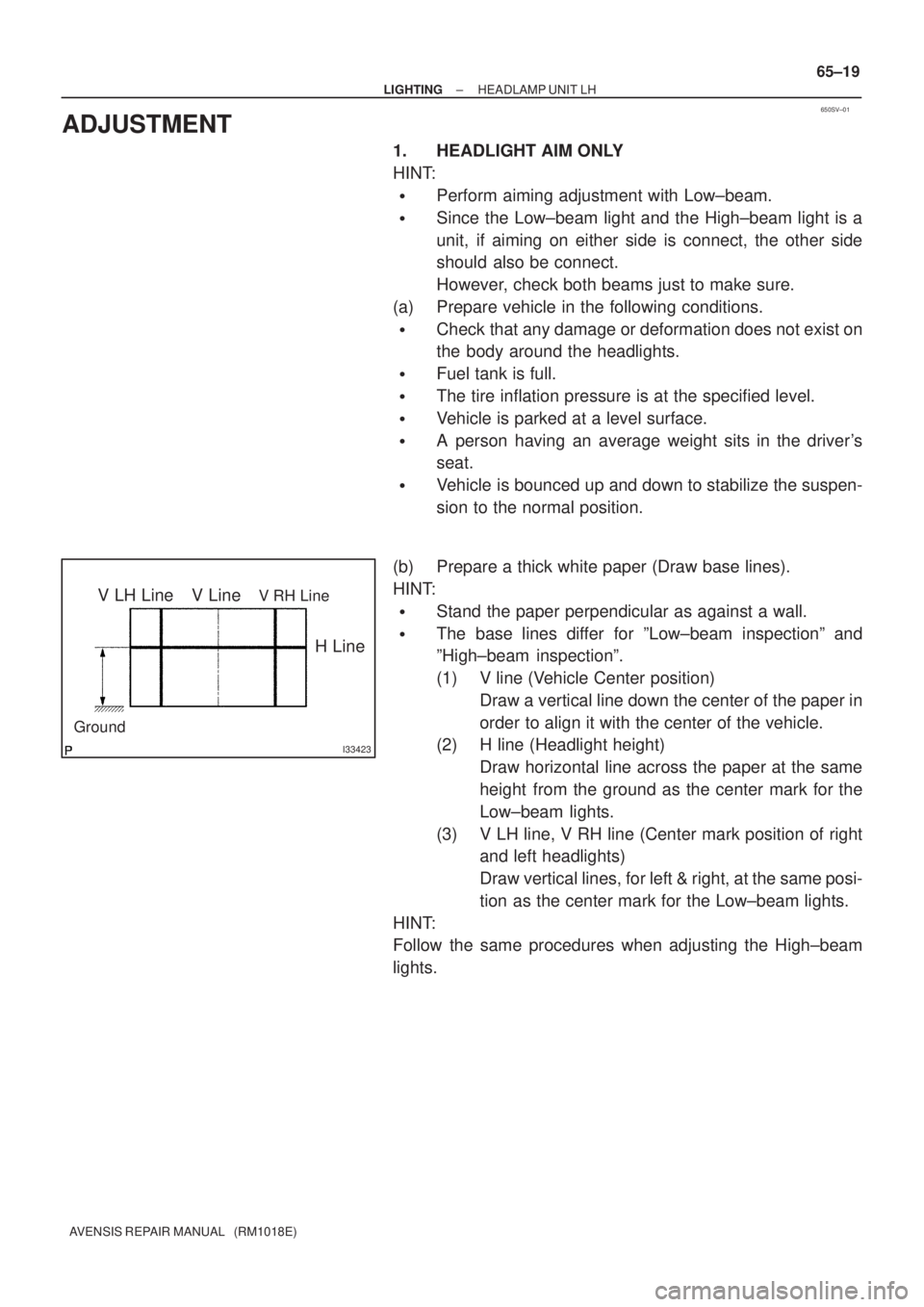
(b) Prepare a thick white paper (Draw base lines).
HINT:
�Stand the paper perpendicular as against a wall.
�The base lines differ for ºLow±beam inspectionº and
ºHigh±beam inspectionº.
(1) V line (Vehicle Center position)
Draw a vertical line down the center of the paper in
order to align it with the center of the vehicle.
(2) H line (Headlight height)
Draw horizontal line across the paper at the same
height from the ground as the center mark for the
Low±beam lights.
(3) V LH line, V RH line (Center mark position of right
and left headlights)
Draw vertical lines, for left & right, at the same posi-
tion as the center mark for the Low±beam lights.
HINT:
Follow the same procedures when adjusting the High±beam
lights.
Page 3122 of 5135

670S8±01
������I35168
������I35169
(2)
(1)
(3)
H02440
Riveter
Mandrel
67±10
±
AUDIO & VISUAL SYSTEM FRONT NO.1 SPEAKER ASSY
AVENSIS REPAIR MANUAL (RM1018E)
FRONT NO.1 SPEAKER ASSY
REPLACEMENT
1. REMOVE REAR DOOR WINDOW REGULATOR HANDLE ASSY (W/O POWER WINDOW) (See page 75±8)
2.REMOVE FRONT DOOR LOWER FRAME BRACKET GARNISH LH (See page 75±8)
3.REMOVE FRONT DOOR TRIM BASE LH (See page 75±8)
4.REMOVE FUEL LID OPENER SWITCH (See page 75±8)
5. REMOVE POWER WINDOW REGULATOR SWITCH ASSY (W/ POWER WINDOW) (See page 75±8)
6.REMOVE FRONT DOOR TRIM BOARD SUB±ASSY LH (See page 75±8)
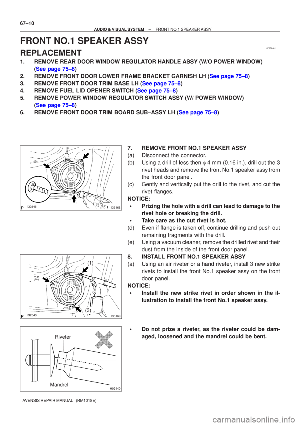
7. REMOVE FRONT NO.1 SPEAKER ASSY
(a) Disconnect the connector.
(b) Using a drill of less then � 4 mm (0.16 in.), drill out the 3
rivet heads and remove the front No.1 speaker assy from
the front door panel.
(c) Gently and vertically put the drill to the rivet, and cut the rivet flanges.
NOTICE:
�Prizing the hole with a drill can lead to damage to the
rivet hole or breaking the drill.
�Take care as the cut rivet is hot.
(d) Even if flange is taken off, continue drilling and push out remaining fragments with the drill.
(e) Using a vacuum cleaner, remove the drilled rivet and their
dust from the inside of the front door panel.
8. INSTALL FRONT NO.1 SPEAKER ASSY
(a) Using an air riveter or a hand riveter, install 3 new strike rivets to install the front No.1 speaker assy on the front
door panel.
NOTICE:
�Install the new strike rivet in order shown in the il-
lustration to install the front No.1 speaker assy.
�Do not prize a riveter, as the riveter could be dam-
aged, loosened and the mandrel could be bent.