Page 3158 of 5135
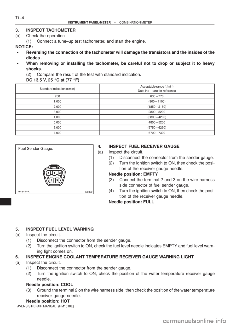
I35138
LHD:
FUSE
1. ±
2. DEF I/ UP 7.5A
3. ST 7.5A
4. MIR HTR 7.5A
5. RAD No.2 15A6. DOME 7.5A
7. ECU±B2 7.5A
8. PWR SEAT 30A
9. ±
10. P±RR P/W 20A11. P±FR P/W 20A
12. D±RR P/W 20A
13. D±FR P/W 20A
14. ECU±B1 7.5A
15. FUEL OPN 10A
16. FR DIC 20A
RELAY
A. ST
B. FR FOG
C. P/POINT
D. FR DEICER
A
B
13 14 15 934567
8
C
D
16 11 1 2 10 12
Fuse Block Assy
Drive Side Relay Block Assy 68±6
± WIRINGPOWER SOURCE
AVENSIS REPAIR MANUAL (RM1018E)
Page 3159 of 5135
I35137
AB
CD
13 14 15 93 456 7
8
16 10 1211 12
RHD:
Fuse Block Assy
FUSE
1. ±
2. DEF I/ UP 7.5A
3. ST 7.5A
4. MIR HTR 10A
5. RAD No.2 15A6. DOME 7.5A
7. ECU±B2 7.5A
8. PWR SEAT 30A
9. ±
10. P±RR P/W 20A11. D±FR P/W 20A
12. P±RR P/W 20A
13. P±FR P/W 20A
14. ECU±B1 7.5A
15. FUEL OPN 10A
16. FR DIC 20A
Passenger Side Relay Block Assy
RELAY
A. P/POINT
B. FR FOG
C. ST
D. FR DEICER
± WIRINGPOWER SOURCE
68±7
AVENSIS REPAIR MANUAL (RM1018E)
Page 3236 of 5135

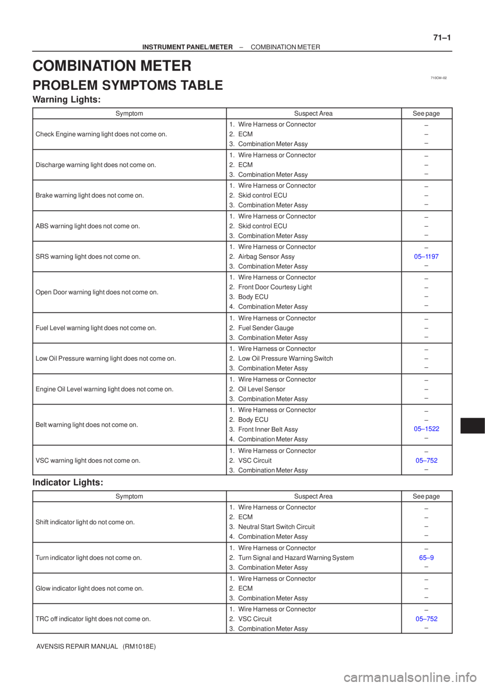
I30899
Fuel Sender Gauge: 71±4
± INSTRUMENT PANEL/METERCOMBINATION METER
AVENSIS REPAIR MANUAL (RM1018E)
3. INSPECT TACHOMETER
(a) Check the operation
(1) Connect a tune±up test tachometer, and start the engine.
NOTICE:
�Reversing the connection of the tachometer will damage the transistors and the insides of the
diodes .
�When removing or installing the tachometer, be careful not to drop or subject it to heavy
shocks.
(2) Compare the result of the test with standard indication.
DC 13.5 V, 25 �C at (77 �F)
Standard indication (r/min)Acceptable range (r/min)
Data in ( ) are for reference
700630 ± 770
1,000(900 ± 1100)
2,000(1850 ± 2150)
3,0002800 ± 3200
4,000(3800 ± 4200)
5,0004800 ± 5200
6,000(5750 ± 6250)
7,0006700 ± 7300
4. INSPECT FUEL RECEIVER GAUGE
(a) Inspect the circuit.
(1) Disconnect the connector from the sender gauge.
(2) Turn the ignition switch to ON, then check the posi-
tion of the receiver gauge needle.
Needle position: EMPTY
(3) Connect the terminal 2 and 3 on the wire harness
side connector of fuel sender gauge.
(4) Turn the ignition switch to ON, then check the posi-
tion of the receiver gauge needle.
Needle position: FULL
5. INSPECT FUEL LEVEL WARNING
(a) Inspect the circuit.
(1) Disconnect the connector from the sender gauge.
(2) Turn the ignition switch to ON, check the fuel level needle indicates EMPTY and fuel level warn-
ing light comes on.
6. INSPECT ENGINE COOLANT TEMPERATURE RECEIVER GAUGE WARNING LIGHT
(a) Inspect the circuit.
(1) Disconnect the connector from the sender gauge.
(2) Turn the ignition switch to ON, check the position of the water temperature receiver gauge
needle.
Needle position: COOL
(3) Ground the terminal 2 on the wire harness side, then check the position of the water temperature
receiver gauge needle.
Needle position: HOT
Page 3239 of 5135

710CM±02
±
INSTRUMENT PANEL/METER COMBINATION METER
71±1
AVENSIS REPAIR MANUAL (RM1018E)
COMBINATION METER
PROBLEM SYMPTOMS TABLE
Warning Lights:
SymptomSuspect AreaSee page
Check Engine warning light does not come on.
1.Wire Harness or Connector
2.ECM
3.Combination Meter Assy±
±
±
Discharge warning light does not come on.
1.Wire Harness or Connector
2.ECM
3.Combination Meter Assy±
±
±
Brake warning light does not come on.
1.Wire Harness or Connector
2.Skid control ECU
3.Combination Meter Assy±
±
±
ABS warning light does not come on.
1.Wire Harness or Connector
2.Skid control ECU
3.Combination Meter Assy±
±
±
SRS warning light does not come on.
1.Wire Harness or Connector
2.Airbag Sensor Assy
3.Combination Meter Assy±
05±1197 ±
Open Door warning light does not come on.
1.Wire Harness or Connector
2.Front Door Courtesy Light
3.Body ECU
4.Combination Meter Assy±
±
±
±
Fuel Level warning light does not come on.
1.Wire Harness or Connector
2.Fuel Sender Gauge
3.Combination Meter Assy±
±
±
Low Oil Pressure warning light does not come on.
1.Wire Harness or Connector
2.Low Oil Pressure Warning Switch
3.Combination Meter Assy±
±
±
Engine Oil Level warning light does not come on.
1.Wire Harness or Connector
2.Oil Level Sensor
3.Combination Meter Assy±
±
±
Belt warning light does not come on.
1.Wire Harness or Connector
2.Body ECU
3.Front Inner Belt Assy
4.Combination Meter Assy±
±
05±1522
±
VSC warning light does not come on.
1.Wire Harness or Connector
2.VSC Circuit
3.Combination Meter Assy±
05±752 ±
Indicator Lights:
SymptomSuspect AreaSee page
Shift indicator light do not come on.
1. Wire Harness or Connector
2. ECM
3. Neutral Start Switch Circuit
4. Combination Meter Assy±
±
±
±
Turn indicator light does not come on.
1. Wire Harness or Connector
2. Turn Signal and Hazard Warning System
3. Combination Meter Assy±
65±9 ±
Glow indicator light does not come on.
1. Wire Harness or Connector
2. ECM
3. Combination Meter Assy±
±
±
TRC off indicator light does not come on.
1. Wire Harness or Connector
2. VSC Circuit
3. Combination Meter Assy±
05±752 ±
Page 3240 of 5135

71±2
±
INSTRUMENT PANEL/METER COMBINATION METER
AVENSIS REPAIR MANUAL (RM1018E)
SLIP indicator light does not come on.
1.Wire Harness or Connector
2.Skid Control ECU
3.Combination Meter Assy±
05±752 ±
CRUISE indicator light does not come on.
1.Wire Harness or Connector
2.ECM
3.Combination Meter Assy±
±
±
High Beam indicator light does not come on.
1.Wire Harness or Connector
2.Headlight Dimmer Switch
3.Combination Meter Assy±
65±9 ±
Fr FOG indicator does not come on.
1.Wire Harness or Connector
2.Fr FOG Relay
3.Fr FOG Light Switch
4.Combination Meter Assy±
±
±
±
Rr FOG indicator does not come on.
1.Wire Harness or Connector
2.Rr FOG Relay
3.Rr FOG Light Switch
4.Combination Meter Assy±
±
±
±
TAIL indicator does not come on.
1.Wire Harness or Connector
2.TAIL Relay
3.Combination Meter Assy±
±
±
WATER LEVEL indicator does not come on (1KD±FTV).
1.Wire Harness or Connector
2.Water Level Sensor
3.Combination Meter Assy±
±
±
EMPS indicator does not come on.
1.Wire Harness or Connector
2.EMPS ECU
3.Combination Meter Assy±
±
±
A/T OIL TEMP indicator does not come on.
1.Refer to troubleshooting
2.Wire Harness or Connector
3.Combination Meter Assy05±856
±
±
ECT SNOW indicator does not come on.
1.Refer to troubleshooting
2.Wire Harness or Connector
3.Combination Meter Assy05±980±
±
AUTO LEVELING indicator does not come on.
1.Wire Harness or Connector
2.Auto Leveling ECU
3.Combination Meter Assy±
±
±
Meter Gauges:
SymptomSuspect AreaSee page
Speedometer does not operate.1.Refer to troubleshooting05±1510
Water temperature does not operate.1.Refer to troubleshooting05±1515
Tachometer does not operate.1.Refer to troubleshooting05±1513
Fuel Gauge does not operate or operates abnormally.1.Refer to troubleshooting05±1517
OTHERS:
SymptomSuspect AreaSee page
key reminder buzzer does not operate.
1. Wire Harness or Connector
2. Body ECU (KSW, DCTY)
3. Door Coutesy Switch
4. Key Unlock Warning Switch
5. Combination Meter Assy±
±
±
05±1586 ±
Light reminder buzzer does not operate.
1. Wire Harness or Connector
2. Body ECU (DCTY)
3. Combination Meter Assy±
±
±
Seat belt Warning buzzer does not operate.
1. Perform DATA LIST with hand±held tester
2. Wire Harness or Connector
3. Seat Belt Buckle Switch
4. Combination Meter Assy05±1499±
61±3
±
Page 3241 of 5135

700TI±01
B68929
B68929
±
WINDSHIELD/WINDOWGLASS/MIRROR OUTER REAR VIEW MIRROR ASSY LH
70±65
AVENSIS REPAIR MANUAL (RM1018E)
OUTER REAR VIEW MIRROR ASSY LH
REPLACEMENT
HINT:
�The installation is in the reverse order of the removal. However, when there is a special point concern-
ing the installation, it is indicated.
�Use the same procedures on the RH side as on the LH side.
1.REMOVE FRONT DOOR HOLE COVER SUB±ASSY NO.1 LH (See page 75±8)
(a) Remove the front door lower frame bracket garnish.
(b) Remove the front door trim base.
(c) Only driver side: Remove the fuel lid opener switch.
(d) w/ Power window: Remove the power window regulator switch.
(e) Remove the front door trim board sub.
(f) Remove the front door inside handle.
(g) remove the front service hole cover No. 1.
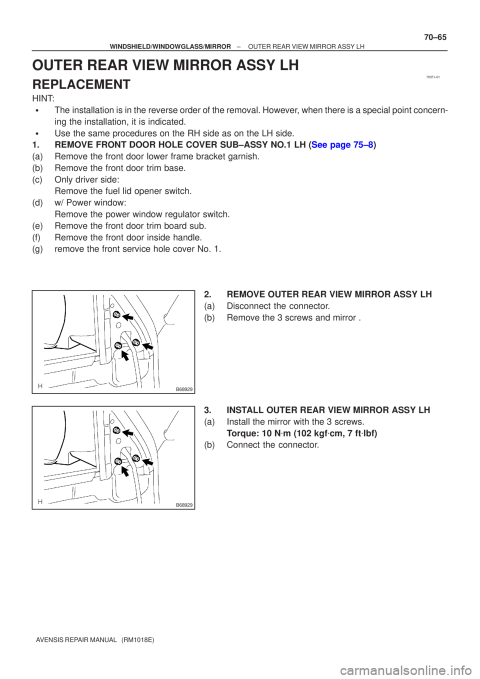
2. REMOVE OUTER REAR VIEW MIRROR ASSY LH
(a) Disconnect the connector.
(b) Remove the 3 screws and mirror .
3. INSTALL OUTER REAR VIEW MIRROR ASSY LH
(a) Install the mirror with the 3 screws.Torque: 10 N �m (102 kgf �cm, 7 ft �lbf)
(b) Connect the connector.
Page 3304 of 5135
73095±02
B68828
Fuel Lid Opener Switch
B68829
Shaft Strokes
Open 73±30
± THEFT DETERRENT & DOOR LOCKFUEL LID OPENER SYSTEM
AVENSIS REPAIR MANUAL (RM1018E)
INSPECTION
1. INSPECT FUEL LID OPENER SWITCH
(a) Check the switch resistance.
Standard:
Tester ConnectionSwitch PositionSpecified Condition
23OFF10 k� or higher2 ± 3ONBelow 1 �
If the result is not as specified, replace the switch.
2. INSPECT FUEL LID LOCK CONTROL ASSY
(a) Apply battery voltage to the lock control and check the
motor operates in the direction.
Standard:
Measurement ConditionSpecified Condition
Battery positive (+) � Terminal 2
Battery negative (±) � Terminal 1Open direction
If the result is not as specified, replace the lock control assy.
(b) Check the shaft strokes.
Standard: 18.0 mm (0.709 in.) or more
Page 3305 of 5135
73094±02
±
THEFT DETERRENT & DOOR LOCK FUEL LID OPENER SYSTEM
73±29
AVENSIS REPAIR MANUAL (RM1018E)
PROBLEM SYMPTOMS TABLE
SymptomSuspected AreaSee Page
Fuel lid opener does not operate.
1. FUEL OPN fuse
2. Fuel lid opener switch
3. Fuel lid lock control assy
4. Wire harness68±1
73±30
73±30