Page 2447 of 5135
± IGNITIONIGNITION SYSTEM (1AZ±FE)
18±11
AVENSIS REPAIR MANUAL (RM1018E)
4. INSPECT CRANKSHAFT POSITION SENSOR
(a) Using an ohmmeter, measure the resistance between the terminals.
RESISTANCE:
985 to 1,600 � at cold
1,265 to 1,890 �at hot
NOTICE:
ºColdº and ºHotº mean the temperature of the coils themselves.ºColdº is from ± 10�C (14�F) to 50
�C (122 �F) and ºHotº is from 50 �C (122 �F) to 100 �C (212 �F).
Page 2448 of 5135

1807M±01
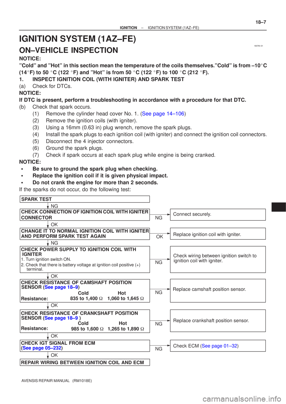
CHECK POWER SUPPLY TO IGNITION COIL WITHSENSOR (See page 18±9)
SPARK TEST
Replace crankshaft position sensor.
CHECK RESISTANCE OF CAMSHAFT POSITION
1. Turn ignition switch ON.
2. Check that there is battery voltage at ignition coil positive (+) terminal.
CHECK CONNECTION OF IGNITION COIL WITH IGNITER
Resistance: ColdHot
1,060 to 1,645 �
CHECK RESISTANCE OF CRANKSHAFT POSITION
Resistance: ColdHot
985 to 1,600 �1,265 to 1,890 �
CHECK IGT SIGNAL FROM ECM
(See page 05±232)
REPAIR WIRING BETWEEN IGNITION COIL AND ECM Connect securely.
Check wiring between ignition switch to ignition coil with igniter.
Check ECM (See page 01±32)
NG
OK
OK
OK
OK NG
NG
NG
NG
NG
SENSOR (See page 18±9 )
835 to 1,400
�
IGNITER
CHANGE IT TO NORMAL IGNITION COIL WITH IGNITER
AND PERFORM SPARK TEST AGAIN
OK
Replace ignition coil with igniter.
NG
OK
CONNECTOR
Replace camshaft position sensor.
±
IGNITION IGNITION SYSTEM(1AZ±FE)
18±7
AVENSIS REPAIR MANUAL (RM1018E)
IGNITION SYSTEM(1AZ±FE)
ON±VEHICLE INSPECTION
NOTICE:
ºColdº and ºHotº in this section mean the temperature of the coils thems\
elves.ºColdº is from ±10 �C
(14 �F) to 50 �C (122 �F) and ºHotº is from 50 �C (122 �F) to 100 �C (212 �F).
1.INSPECT IGNITION COIL (WITH IGNITER) AND SPARK TEST
(a)Check for DTCs.
NOTICE:
If DTC is present, perform a troubleshooting in accordance with a proced\
ure for that DTC.
(b)Check that spark occurs. (1)Remove the cylinder head cover No. 1. (See page 14±106)
(2) Remove the ignition coils (with igniter).
(3) Using a 16mm (0.63 in) plug wrench, remove the spark plugs.
(4) Install the spark plugs to each ignition coil (with igniter) and connect the \
ignition coil connectors.
(5) Disconnect the 4 injector connectors.
(6) Ground the spark plugs.
(7) Check if spark occurs at each spark plug while engine is being cranked.
NOTICE:
�Be sure to ground the spark plug when checking.
�Replace the ignition coil if it is given physical impact.
�Do not crank the engine for more than 2 seconds.
If the sparks do not occur, do the following test:
Page 2452 of 5135
1807P±01
A50033
P03783
P03792
± IGNITIONIGNITION SYSTEM (1ZZ±FE/3ZZ±FE)
18±3
AVENSIS REPAIR MANUAL (RM1018E)
INSPECTION
1. INSPECT SPARK PLUG
(a) Clean the spark plugs.
If the electrode has traces of wet carbon, clean the electrode
with a spark plug cleaner then dry it.
Air pressure: Below 588 kPa (6kg/cm
2, 85 psi)
Duration: 20 seconds or less
(b) Check the spark plug for any damage on its thread and
insulator damage.
If there is damage, replace the spark plug.
Recommended spark plug:
DENSO madeK16R±U11
NGK madeBKR5EYA11
(c) Adjust electrode gap.
Electrode gap: 1.0 to 1.1 mm (0.039 to 0.043 in.)
2. INSPECT CAMSHAFT POSITION SENSOR
(a) Using an ohmmeter, measure the resistance between the terminals.
RESISTANCE:
835 to 1,400 � at cold
1,060 to 1,645 �at hot
NOTICE:
ºColdº and ºHotº mean the temperature of the coils themselves.ºColdº is from ± 10�C (14�F) to 50
�C (122 �F) and ºHotº is from 50 �C (122 �F) to 100 �C (212 �F).
Page 2453 of 5135
18±4
± IGNITIONIGNITION SYSTEM (1ZZ±FE/3ZZ±FE)
AVENSIS REPAIR MANUAL (RM1018E)
3. INSPECT CRANKSHAFT POSITION SENSOR
(a) Using an ohmmeter, measure the resistance between the terminals.
RESISTANCE:
1,630 to 2,740 � at cold
2,065 to 3,225 �at hot
NOTICE:
ºColdº and ºHotº mean the temperature of the coils themselves.ºColdº is from ± 10�C (14�F) to 50
�C (122 �F) and ºHotº is from 50 �C (122 �F) to 100 �C (212 �F).
Page 2454 of 5135

1807O±01
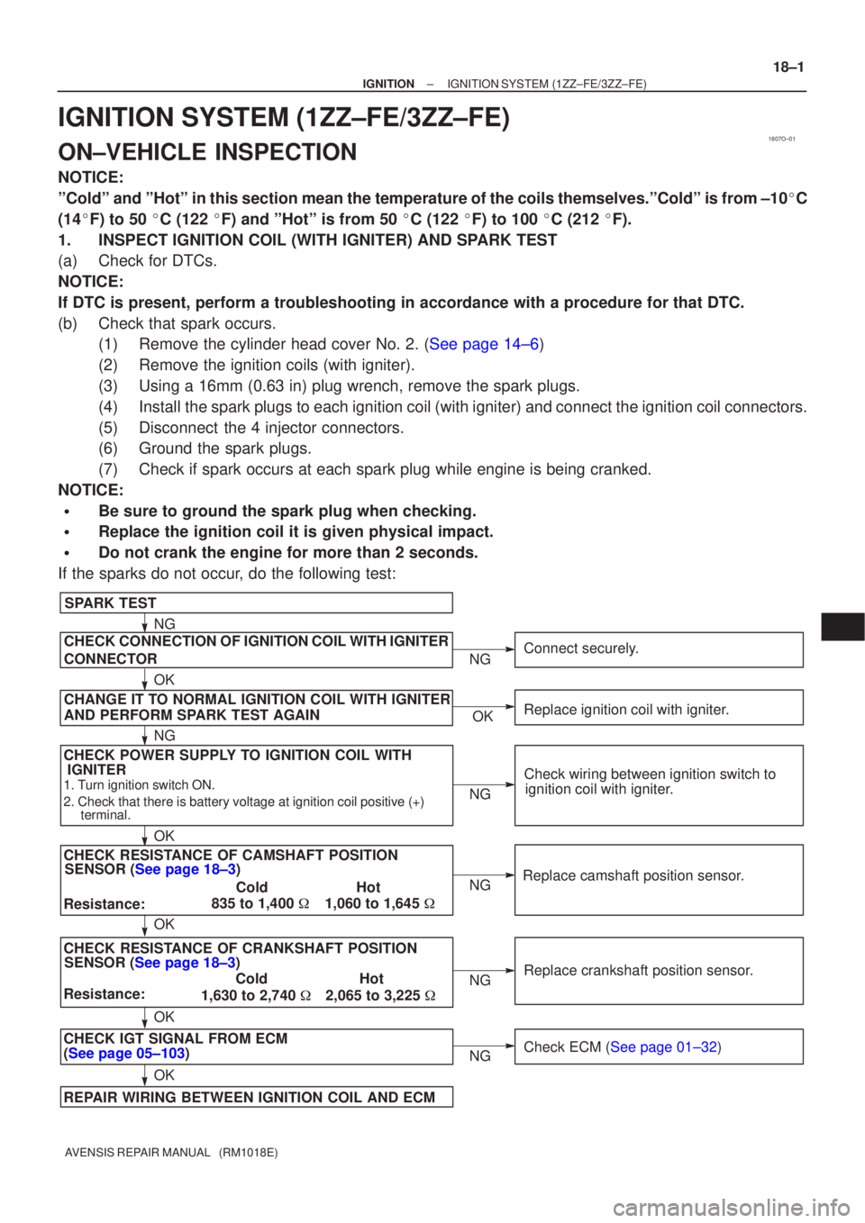
CHECK POWER SUPPLY TO IGNITION COIL WITHSENSOR (See page 18±3)
SPARK TEST
Replace crankshaft position sensor.
CHECK RESISTANCE OF CAMSHAFT POSITION
1. Turn ignition switch ON.
2. Check that there is battery voltage at ignition coil positive (+) terminal.
CHECK CONNECTION OF IGNITION COIL WITH IGNITER
Resistance: ColdHot
1,060 to 1,645 �
CHECK RESISTANCE OF CRANKSHAFT POSITION
Resistance: ColdHot
1,630 to 2,740 �2,065 to 3,225 �
CHECK IGT SIGNAL FROM ECM
(See page 05±103)
REPAIR WIRING BETWEEN IGNITION COIL AND ECM Connect securely.
Check wiring between ignition switch to ignition coil with igniter.
Check ECM (See page 01±32)
NG
OK
OK
OK
OK NG
NG
NG
NG
NG
SENSOR (See page 18±3)
835 to 1,400
�
IGNITER
CHANGE IT TO NORMAL IGNITION COIL WITH IGNITER
AND PERFORM SPARK TEST AGAIN
OK
Replace ignition coil with igniter.
NG
OK
CONNECTOR
Replace camshaft position sensor.
±
IGNITION IGNITION SYSTEM(1ZZ±FE/3ZZ±FE)
18±1
AVENSIS REPAIR MANUAL (RM1018E)
IGNITION SYSTEM(1ZZ±FE/3ZZ±FE)
ON±VEHICLE INSPECTION
NOTICE:
ºColdº and ºHotº in this section mean the temperature of the coils thems\
elves.ºColdº is from ±10 �C
(14 �F) to 50 �C (122 �F) and ºHotº is from 50 �C (122 �F) to 100 �C (212 �F).
1.INSPECT IGNITION COIL (WITH IGNITER) AND SPARK TEST
(a)Check for DTCs.
NOTICE:
If DTC is present, perform a troubleshooting in accordance with a proced\
ure for that DTC.
(b)Check that spark occurs. (1)Remove the cylinder head cover No. 2. (See page 14±6)
(2) Remove the ignition coils (with igniter).
(3) Using a 16mm (0.63 in) plug wrench, remove the spark plugs.
(4) Install the spark plugs to each ignition coil (with igniter) and connect the \
ignition coil connectors.
(5) Disconnect the 4 injector connectors.
(6) Ground the spark plugs.
(7) Check if spark occurs at each spark plug while engine is being cranked.
NOTICE:
�Be sure to ground the spark plug when checking.
�Replace the ignition coil it is given physical impact.
�Do not crank the engine for more than 2 seconds.
If the sparks do not occur, do the following test:
Page 2649 of 5135
400D7±02
D25120
OK if hot
Add if hot 40±2
± AUTOMATIC TRANSMISSION / TRANSAUTOMATIC TRANSAXLE FLUID (ATM)
AVENSIS REPAIR MANUAL (RM1018E)
AUTOMATIC TRANSAXLE FLUID (ATM)
ON±VEHICLE INSPECTION
1. CHECK THE FLUID LEVEL
HINT:
Drive the vehicle so that the engine and transaxle are at the nor-
mal operating temperature.
Fluid temperature: 70 ± 80 �C (158 ± 176 �F)
(a) Park the vehicle on a level surface and set the parking
brake.
(b) With the engine idling and the brake pedal depressed,
shift the shift lever into all position from P to L position and
return to P position.
(c) Pull out the dipstick and wipe it clean.
(d) Push it back fully into the pipe.
(e) Pull it out and check that the fluid level is in the HOT posi-
tion.
If there are leaks, it is necessary to repair or replace O±rings,
FIPGs, oil seals, plugs or other parts.
Page 2675 of 5135

400DD±02
C83111
AT0103
D25591
C50009
40±52
± AUTOMATIC TRANSMISSION / TRANSTRANSMISSION WIRE (U241E)
AVENSIS REPAIR MANUAL (RM1018E)
TRANSMISSION WIRE (U241E)
REPLACEMENT
1. REMOVE ENGINE UNDER COVER LH
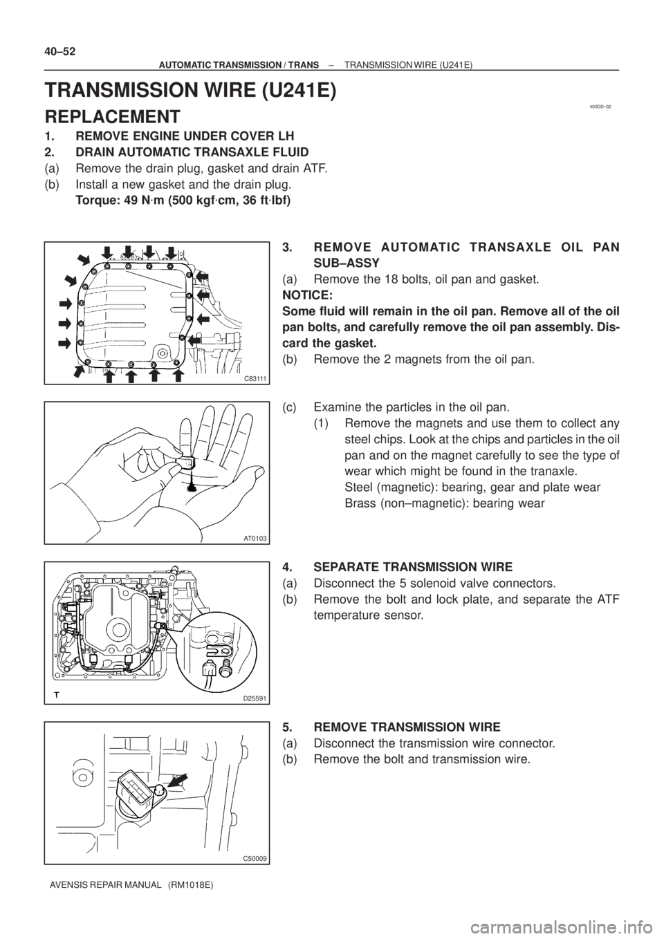
2. DRAIN AUTOMATIC TRANSAXLE FLUID
(a) Remove the drain plug, gasket and drain ATF.
(b) Install a new gasket and the drain plug.
Torque: 49 N�m (500 kgf�cm, 36 ft�lbf)
3. REMOVE AUTOMATIC TRANSAXLE OIL PAN
SUB±ASSY
(a) Remove the 18 bolts, oil pan and gasket.
NOTICE:
Some fluid will remain in the oil pan. Remove all of the oil
pan bolts, and carefully remove the oil pan assembly. Dis-
card the gasket.
(b) Remove the 2 magnets from the oil pan.
(c) Examine the particles in the oil pan.
(1) Remove the magnets and use them to collect any
steel chips. Look at the chips and particles in the oil
pan and on the magnet carefully to see the type of
wear which might be found in the tranaxle.
Steel (magnetic): bearing, gear and plate wear
Brass (non±magnetic): bearing wear
4. SEPARATE TRANSMISSION WIRE
(a) Disconnect the 5 solenoid valve connectors.
(b) Remove the bolt and lock plate, and separate the ATF
temperature sensor.
5. REMOVE TRANSMISSION WIRE
(a) Disconnect the transmission wire connector.
(b) Remove the bolt and transmission wire.
Page 2676 of 5135

D03636
C50009
D25591
D25674
Magnet
C83111
± AUTOMATIC TRANSMISSION / TRANSTRANSMISSION WIRE (U241E)
40±53
AVENSIS REPAIR MANUAL (RM1018E)
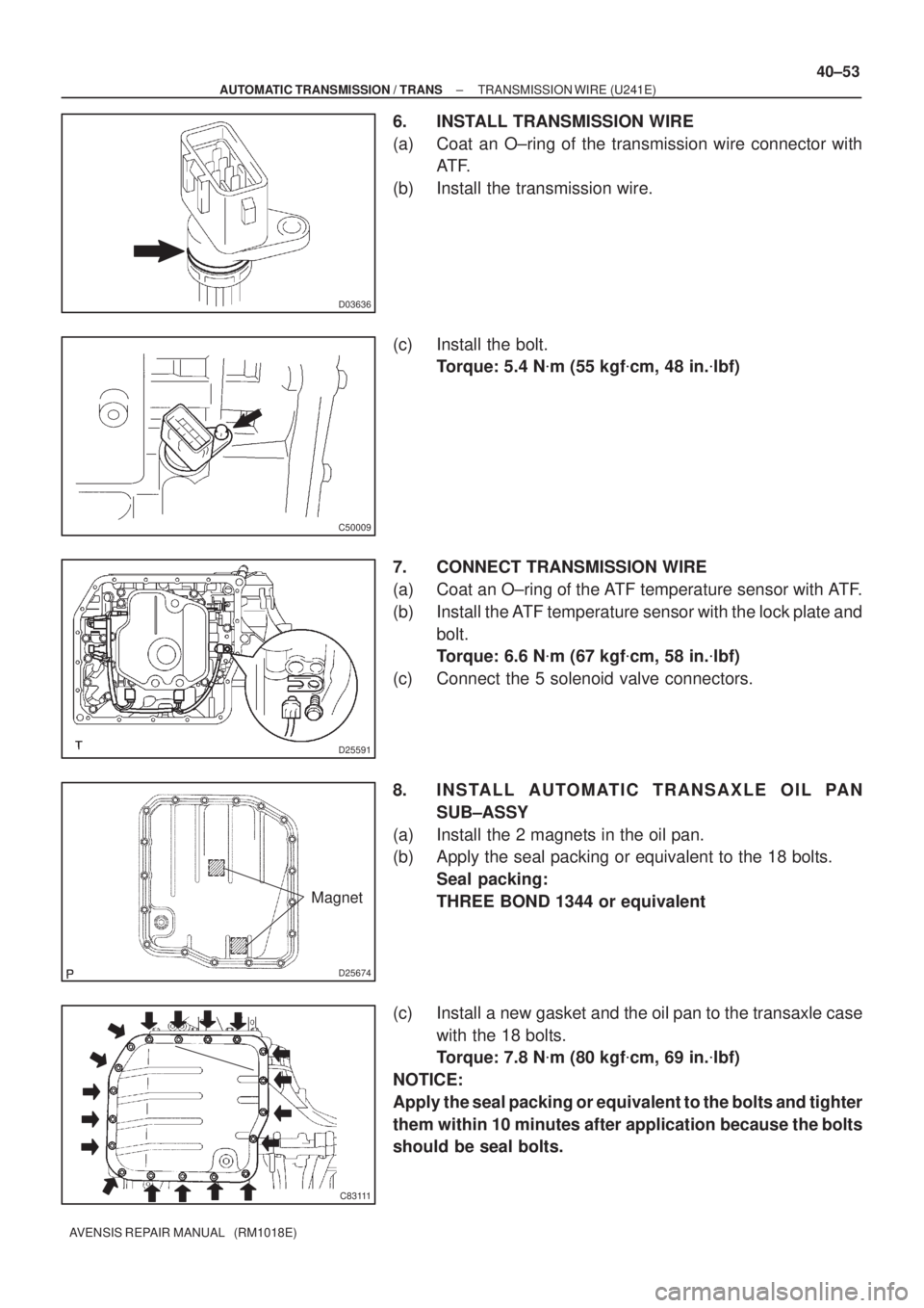
6. INSTALL TRANSMISSION WIRE
(a) Coat an O±ring of the transmission wire connector with
AT F.
(b) Install the transmission wire.
(c) Install the bolt.
Torque: 5.4 N�m (55 kgf�cm, 48 in.�lbf)
7. CONNECT TRANSMISSION WIRE
(a) Coat an O±ring of the ATF temperature sensor with ATF.
(b) Install the ATF temperature sensor with the lock plate and
bolt.
Torque: 6.6 N�m (67 kgf�cm, 58 in.�lbf)
(c) Connect the 5 solenoid valve connectors.
8. INSTALL AUTOMATIC TRANSAXLE OIL PAN
SUB±ASSY
(a) Install the 2 magnets in the oil pan.
(b) Apply the seal packing or equivalent to the 18 bolts.
Seal packing:
THREE BOND 1344 or equivalent
(c) Install a new gasket and the oil pan to the transaxle case
with the 18 bolts.
Torque: 7.8 N�m (80 kgf�cm, 69 in.�lbf)
NOTICE:
Apply the seal packing or equivalent to the bolts and tighter
them within 10 minutes after application because the bolts
should be seal bolts.