Page 1913 of 5135
A62779SST
A79153
A62166
SST
11±72
±
FUEL INJECTION OR SUPPLY PUMP ASSY(1CD±FTV)
AVENSIS REPAIR MANUAL (RM1018E)
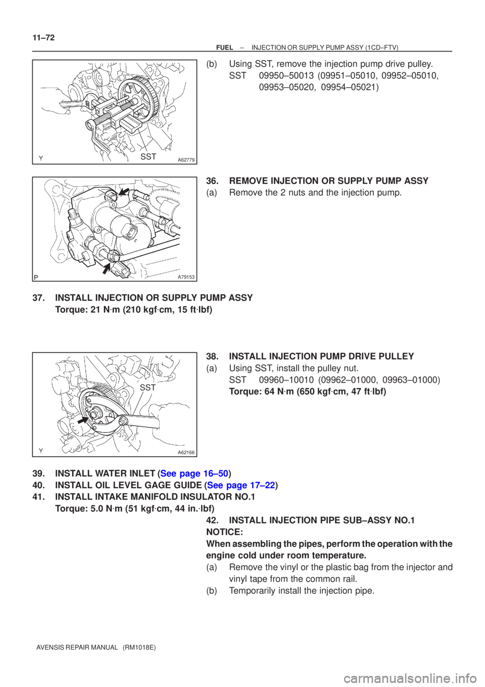
(b)Using SST, remove the injection pump drive pulley. SST09950±50013 (09951±05010, 09952±05010, 09953±05020, 09954±05021)
36.REMOVE INJECTION OR SUPPLY PUMP ASSY
(a)Remove the 2 nuts and the injection pump.
37.INSTALL INJECTION OR SUPPLY PUMP ASSY Torque: 21 N �m (210 kgf �cm, 15 ft �lbf)
38.INSTALL INJECTION PUMP DRIVE PULLEY
(a)Using SST, install the pulley nut. SST09960±10010 (09962±01000, 09963±01000)
Torque: 64 N �m (650 kgf �cm, 47 ft �lbf)
39.INSTALL WATER INLET(See page 16±50)
40.INSTALL OIL LEVEL GAGE GUIDE(See page 17±22)
41. INSTALL INTAKE MANIFOLD INSULATOR NO.1 Torque: 5.0 N �m (51 kgf �cm, 44 in. �lbf)
42. INSTALL INJECTION PIPE SUB±ASSY NO.1
NOTICE:
When assembling the pipes, perform the operation with the
engine cold under room temperature.
(a) Remove the vinyl or the plastic bag from the injector and vinyl tape from the common rail.
(b) Temporarily install the injection pipe.
Page 2077 of 5135
A77332
23
145
±
ENGINE MECHANICAL PARTIAL ENGINE ASSY(1AZ±FE)
14±129
AVENSIS REPAIR MANUAL (RM1018E)
91.REMOVE KNOCK SENSOR
(a)Remove the nut and the knock sensor.
92.REMOVE ENGINE COOLANT TEMPERATURE SENSOR
(a)Using SST, remove the engine coolant temperature sensor.
SST09817±33190
93.REPLACE PARTIAL ENGINE ASSY
94.INSTALL ENGINE COOLANT TEMPERATURE SENSOR
(a)Install a new gasket to the engine coolant temperature sensor.
(b)Install the engine coolant temperature sensor. Torque: 20 N �m (208 kgf �cm,15 ft �lbf)
SST09817±33190
95.INSTALL KNOCK SENSOR
Torque: 20 N �m (208 kgf �cm,15 ft �lbf)
96.INSTALL ENGINE OIL PRESSURE SWITCH ASSY
(a)Clean the threads of the oil pressure switch, apply adhesive there. Adhesive: Part No. 08833±00080 THREE BOND 1344 or equivalent
(b)Install the oil pressure switch. Torque: 15 N �m (153 kgf �cm,11 ft �lbf)
97.INSTALL WATER BY±PASS PIPE NO.1
(a)Install a new gasket and the water by±pass pipe No. 1 with the bolt a\
nd 2 nuts. Torque: 9.0 N �m (92 kgf �cm,80 in. �lbf)
98.INSTALL FUEL DELIVERY PIPE W/INJECTOR (See page 11±26)
99.INSTALL DRIVE SHAFT BEARING BRACKET Torque: 54 N �m (551 kgf �cm,40 ft �lbf)
100.INSTALL V±RIBBED BELT TENSIONER ASSY
Torque: 60 N �m (607 kgf �cm,44 ft �lbf)
101.INSTALL IGNITION COIL ASSY Torque: 9.0 N �m (92 kgf �cm,80 in. �lbf)
102.INSTALL THERMOSTAT (See page 16±23)
103. INSTALL WATER INLET
Torque: 9.0 N �m (92 kgf �cm, 80 in. �lbf)
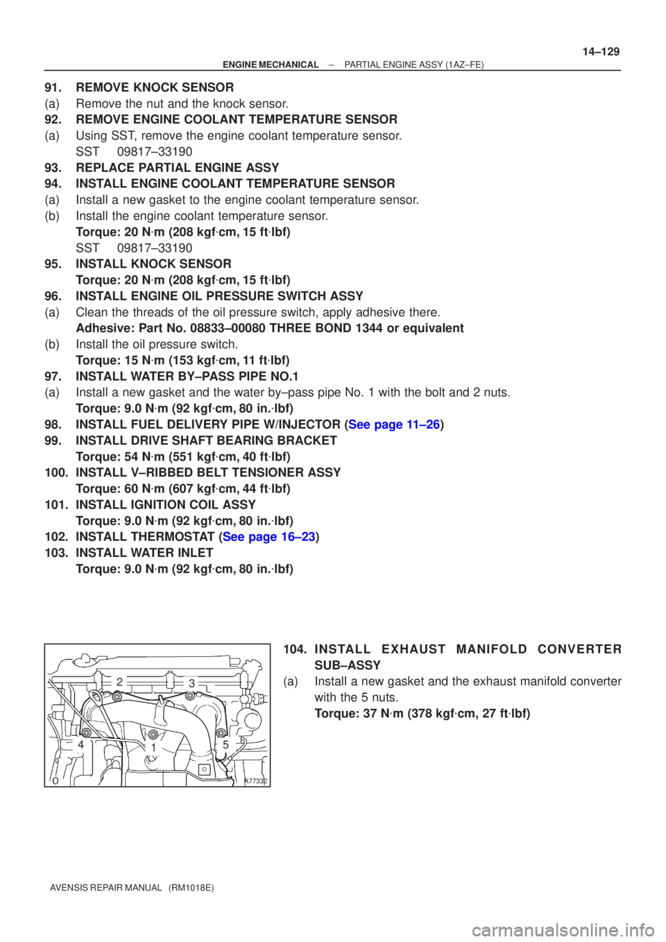
104. I N S TA L L E X HAUST MANIFOLD CONVERTER
SUB±ASSY
(a) Install a new gasket and the exhaust manifold converter
with the 5 nuts.
Torque: 37 N �m (378 kgf �cm, 27 ft �lbf)
Page 2092 of 5135
A79295
N´m (kgf´cm, ft´lbf)
: Specified torque
� Non±reusable part
5.0 (50, 43 in.�lbf)
� O±ring
� Gasket� Gasket� Gasket � Gasket
� O±ring
15 (153, 11)
20 (204, 15)
9.0 (92, 80 in.�lbf)
9.0 (92, 80 in.�lbf)
Fuel Delivery Pipe
w/ Injector
Oil Control Valve
Knock Control SensorSpacer
Water By±pass Pipe No. 1
Oil Level Gauge
Sub±assy
Oil Level Gauge Guide
Water Inlet
9.0 (92, 79 in.�lbf)Engine Oil Pressure Switch Assy
Water Temperature Sensor
Thermostat
9.0 (92, 80 in.�lbf)
19 (194, 14)
19 (194, 14)
20 (204, 15)
14±120
± ENGINE MECHANICALPARTIAL ENGINE ASSY (1AZ±FE)
AVENSIS REPAIR MANUAL (RM1018E)
Page 2208 of 5135
A78645
Oil Pressure Switch
14±212
±
ENGINE MECHANICAL PARTIAL ENGINE ASSY(1AZ±FSE)
AVENSIS REPAIR MANUAL (RM1018E)
94.REMOVE WATER BY±PASS PIPE NO.1
(a)Remove the 2 bolts and 2 nuts.
(b)Remove the water by±pass pipe No. 1 and a gasket.
95.REMOVE KNOCK SENSOR
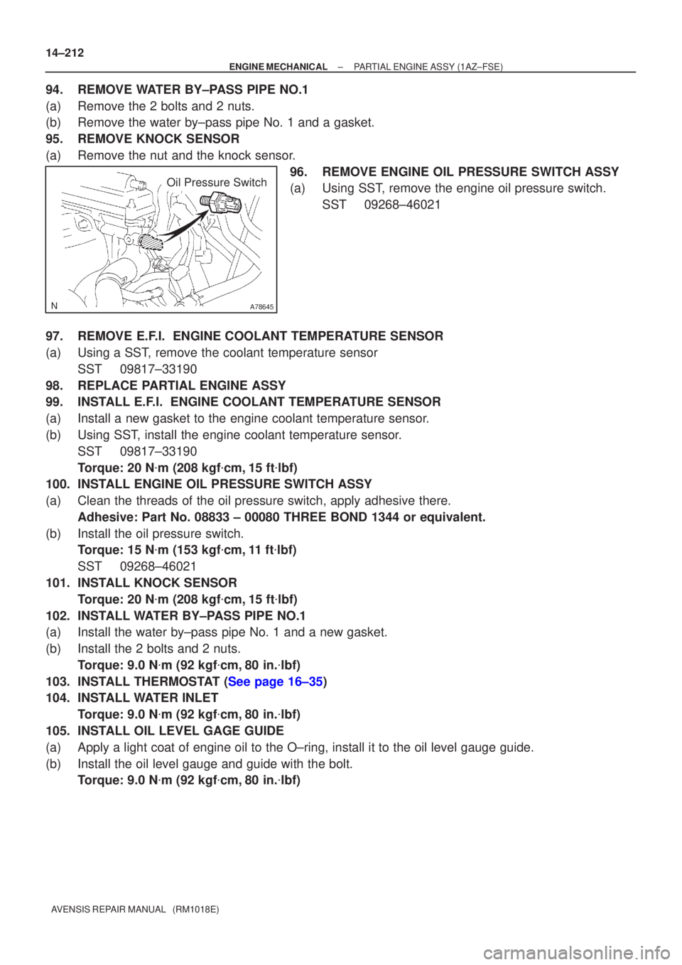
(a)Remove the nut and the knock sensor. 96.REMOVE ENGINE OIL PRESSURE SWITCH ASSY
(a)Using SST, remove the engine oil pressure switch.SST09268±46021
97.REMOVE E.F.I. ENGINE COOLANT TEMPERATURE SENSOR
(a)Using a SST, remove the coolant temperature sensor SST09817±33190
98.REPLACE PARTIAL ENGINE ASSY
99.INSTALL E.F.I. ENGINE COOLANT TEMPERATURE SENSOR
(a)Install a new gasket to the engine coolant temperature sensor.
(b)Using SST, install the engine coolant temperature sensor. SST09817±33190
Torque: 20 N �m (208 kgf �cm,15 ft �lbf)
100.INSTALL ENGINE OIL PRESSURE SWITCH ASSY
(a)Clean the threads of the oil pressure switch, apply adhesive there.
Adhesive: Part No. 08833 ± 00080 THREE BOND 1344 or equivalent.
(b)Install the oil pressure switch. Torque: 15 N �m (153 kgf �cm,11 ft �lbf)
SST09268±46021
101.INSTALL KNOCK SENSOR Torque: 20 N �m (208 kgf �cm,15 ft �lbf)
102.INSTALL WATER BY±PASS PIPE NO.1
(a)Install the water by±pass pipe No. 1 and a new gasket.
(b)Install the 2 bolts and 2 nuts. Torque: 9.0 N �m (92 kgf �cm,80 in. �lbf)
103.INSTALL THERMOSTAT (See page 16±35)
104. INSTALL WATER INLET Torque: 9.0 N �m (92 kgf �cm, 80 in. �lbf)
105. INSTALL OIL LEVEL GAGE GUIDE
(a) Apply a light coat of engine oil to the O±ring, install it to the oil\
level gauge guide.
(b) Install the oil level gauge and guide with the bolt. Torque: 9.0 N �m (92 kgf �cm, 80 in. �lbf)
Page 2225 of 5135
A77370
N´m (kgf´cm, ft´lbf)
: Specified torque
� Non±reusable part� O±ring
13 (127, 9.0)
� E±ring
� O±ring
Nozzle Holder Clamp
Fuel Injector
� Gasket
� Fuel Injector Seal
Fuel Delivery Pipe Sub±assy
19 (194, 14)
Camshaft Timing
Oil Control Valve
� O±ring
20 (208, 15)
Knock Sensor
Insulator No. 2
15 (153, 11)
Engine Oil Pressure
Switch Assy
20 (208, 15)
E. F. I. Engine Coolant
Temperature Sensor
Surge Tank Stay No. 1
9.0 (92, 79 in.�lbf)
21 (210, 15)
� Back Up Ring No. 3
� Back Up Ring No. 2
� Back Up Ring No. 1
± ENGINE MECHANICALPARTIAL ENGINE ASSY (1AZ±FSE)
14±203
AVENSIS REPAIR MANUAL (RM1018E)
Page 2291 of 5135
A09663
:Seal Packing
14±338
±
ENGINE MECHANICAL CYLINDER HEAD GASKET(1CD±FTV)
AVENSIS REPAIR MANUAL (RM1018E)
76.INSTALL CAMSHAFT OIL SEAL RETAINER (See page 14±318)
77.INSTALL CAMSHAFT TIMING PULLEY (See page 14±318) SST 09960±10010 (09962±01000, 09963±01000)
78.INSTALL CAMSHAFT POSITION SENSOR (See page 10±64)
79.INSTALL INJECTOR ASSY(See page 11±60)
80.INSTALL NOZZLE LEAKAGE PIPE ASSY(See page 11±60) SST 09992±00242
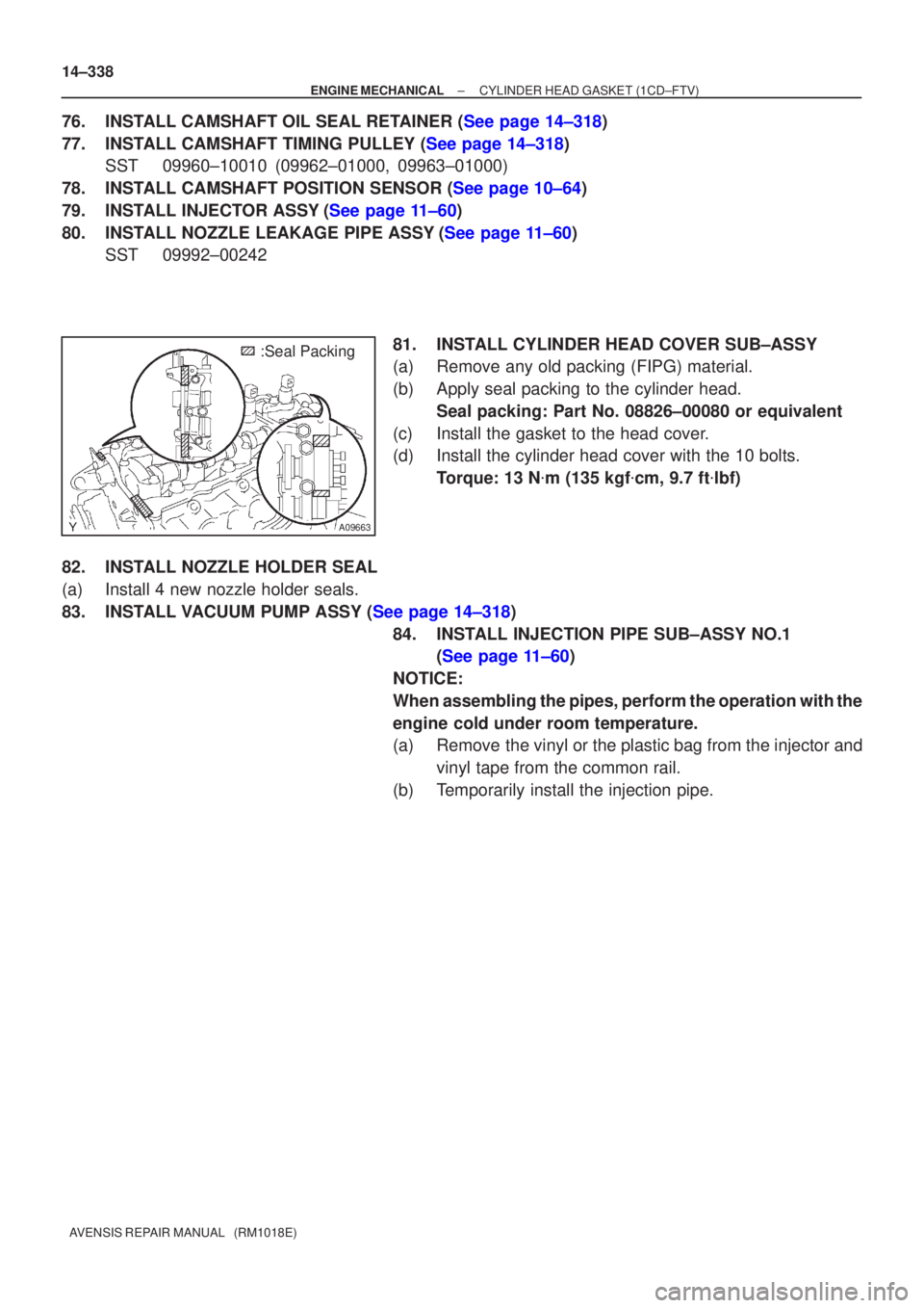
81. INSTALL CYLINDER HEAD COVER SUB±ASSY
(a) Remove any old packing (FIPG) material.
(b) Apply seal packing to the cylinder head.Seal packing: Part No. 08826±00080 or equivalent
(c) Install the gasket to the head cover.
(d) Install the cylinder head cover with the 10 bolts. Torque: 13 N �m (135 kgf �cm, 9.7 ft �lbf)
82. INSTALL NOZZLE HOLDER SEAL
(a) Install 4 new nozzle holder seals.
83.INSTALL VACUUM PUMP ASSY (See page 14±318) 84. INSTALL INJECTION PIPE SUB±ASSY NO.1(See page 11±60)
NOTICE:
When assembling the pipes, perform the operation with the
engine cold under room temperature.
(a) Remove the vinyl or the plastic bag from the injector and vinyl tape from the common rail.
(b) Temporarily install the injection pipe.
Page 2293 of 5135
A79148
SST
A79149
SST
14±340
±
ENGINE MECHANICAL CYLINDER HEAD GASKET(1CD±FTV)
AVENSIS REPAIR MANUAL (RM1018E)
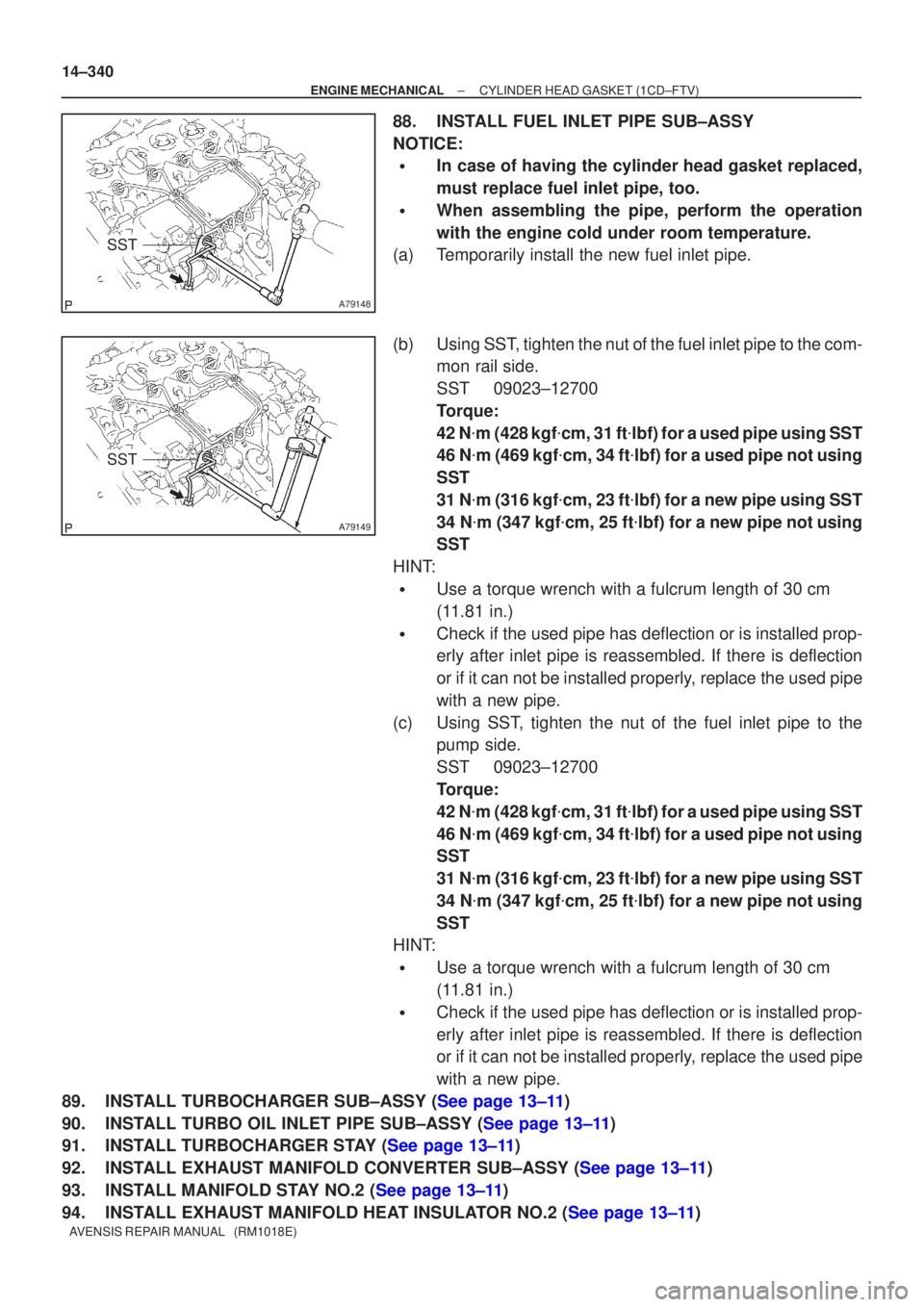
88.INSTALL FUEL INLET PIPE SUB±ASSY
NOTICE:
�In case of having the cylinder head gasket replaced,
must replace fuel inlet pipe, too.
�When assembling the pipe, perform the operation
with the engine cold under room temperature.
(a)Temporarily install the new fuel inlet pipe.
(b)Using SST, tighten the nut of the fuel inlet pipe to the com- mon rail side.
SST09023±12700
Torque:
42 N�m (428 kgf �cm, 31 ft �lbf) for a used pipe using SST
46 N �m (469 kgf �cm, 34 ft �lbf) for a used pipe not using
SST
31 N �m (316 kgf �cm, 23 ft �lbf) for a new pipe using SST
34 N �m (347 kgf �cm, 25 ft �lbf) for a new pipe not using
SST
HINT:
�Use a torque wrench with a fulcrum length of 30 cm
(11.81 in.)
�Check if the used pipe has deflection or is installed prop-
erly after inlet pipe is reassembled. If there is deflection
or if it can not be installed properly, replace the used pipe
with a new pipe.
(c)Using SST, tighten the nut of the fuel inlet pipe to the pump side.
SST09023±12700
Torque:
42 N�m (428 kgf �cm, 31 ft �lbf) for a used pipe using SST
46 N �m (469 kgf �cm, 34 ft �lbf) for a used pipe not using
SST
31 N �m (316 kgf �cm, 23 ft �lbf) for a new pipe using SST
34 N �m (347 kgf �cm, 25 ft �lbf) for a new pipe not using
SST
HINT:
�Use a torque wrench with a fulcrum length of 30 cm
(11.81 in.)
�Check if the used pipe has deflection or is installed prop-
erly after inlet pipe is reassembled. If there is deflection
or if it can not be installed properly, replace the used pipe
with a new pipe.
89.INSTALL TURBOCHARGER SUB±ASSY (See page 13±11)
90.INSTALL TURBO OIL INLET PIPE SUB±ASSY (See page 13±11)
91.INSTALL TURBOCHARGER STAY (See page 13±11)
92.INSTALL EXHAUST MANIFOLD CONVERTER SUB±ASSY (See page 13±11)
93.INSTALL MANIFOLD STAY NO.2 (See page 13±11)
94.INSTALL EXHAUST MANIFOLD HEAT INSULATOR NO.2 (See page 13±11)
Page 2306 of 5135
A62592
SST
A09663
:Seal Packing
±
ENGINE MECHANICAL CAMSHAFT(1CD±FTV)
14±323
AVENSIS REPAIR MANUAL (RM1018E)
(c)Install the oil seal retainer with the 4 bolts. Tighten the 4
bolts uniformly in several steps.
Torque: 8.8 N �m (90 kgf �cm, 78 in. �lbf)
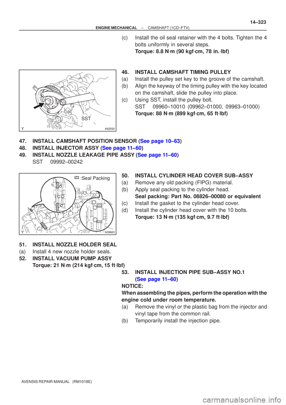
46.INSTALL CAMSHAFT TIMING PULLEY
(a)Install the pulley set key to the groove of the camshaft.
(b)Align the keyway of the timing pulley with the key located on the camshaft, slide the pulley into place.
(c)Using SST, install the pulley bolt. SST09960±10010 (09962±01000, 09963±01000)
Torque: 88 N �m (899 kgf �cm, 65 ft �lbf)
47.INSTALL CAMSHAFT POSITION SENSOR (See page 10±63)
48.INSTALL INJECTOR ASSY (See page 11±60)
49.INSTALL NOZZLE LEAKAGE PIPE ASSY(See page 11±60) SST09992±00242
50.INSTALL CYLINDER HEAD COVER SUB±ASSY
(a)Remove any old packing (FIPG) material.
(b)Apply seal packing to the cylinder head.Seal packing: Part No. 08826±00080 or equivalent
(c)Install the gasket to the cylinder head cover.
(d)Install the cylinder head cover with the 10 bolts.
Torque: 13 N �m (135 kgf �cm, 9.7 ft �lbf)
51.INSTALL NOZZLE HOLDER SEAL
(a)Install 4 new nozzle holder seals.
52.INSTALL VACUUM PUMP ASSY Torque: 21 N �m (214 kgf �cm,15 ft �lbf)
53.INSTALL INJECTION PIPE SUB±ASSY NO.1 (See page 11±60)
NOTICE:
When assembling the pipes, perform the operation with the
engine cold under room temperature.
(a) Remove the vinyl or the plastic bag from the injector and vinyl tape from the common rail.
(b) Temporarily install the injection pipe.