Page 2679 of 5135
400DC±02
C83111
AT0103
D25591
D09179
± AUTOMATIC TRANSMISSION / TRANSTRANSMISSION VALVE BODY ASSY (U241E)
40±47
AVENSIS REPAIR MANUAL (RM1018E)
TRANSMISSION VALVE BODY ASSY (U241E)
REPLACEMENT
1. REMOVE ENGINE UNDER COVER LH
2. DRAIN AUTOMATIC TRANSAXLE FLUID
(a) Remove the drain plug, gasket and drain ATF.
(b) Install a new gasket and the drain plug.
Torque: 49 N�m (500 kgf�cm, 36 ft�lbf)
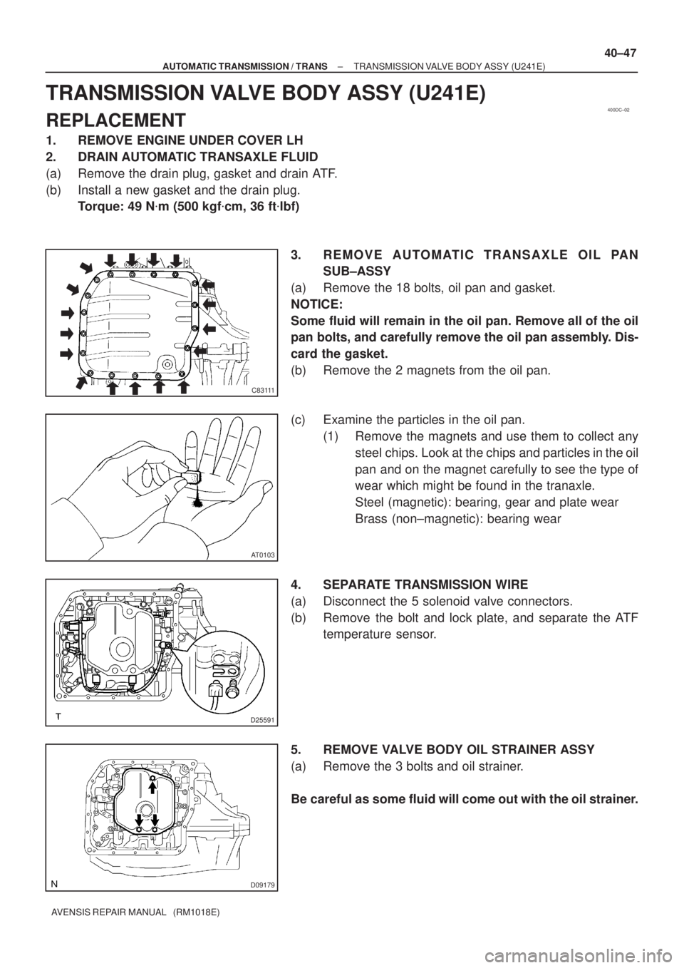
3. REMOVE AUTOMATIC TRANSAXLE OIL PAN
SUB±ASSY
(a) Remove the 18 bolts, oil pan and gasket.
NOTICE:
Some fluid will remain in the oil pan. Remove all of the oil
pan bolts, and carefully remove the oil pan assembly. Dis-
card the gasket.
(b) Remove the 2 magnets from the oil pan.
(c) Examine the particles in the oil pan.
(1) Remove the magnets and use them to collect any
steel chips. Look at the chips and particles in the oil
pan and on the magnet carefully to see the type of
wear which might be found in the tranaxle.
Steel (magnetic): bearing, gear and plate wear
Brass (non±magnetic): bearing wear
4. SEPARATE TRANSMISSION WIRE
(a) Disconnect the 5 solenoid valve connectors.
(b) Remove the bolt and lock plate, and separate the ATF
temperature sensor.
5. REMOVE VALVE BODY OIL STRAINER ASSY
(a) Remove the 3 bolts and oil strainer.
Be careful as some fluid will come out with the oil strainer.
Page 2682 of 5135
D25591
D25674
Magnet
C83111
40±50
±
AUTOMATIC TRANSMISSION / TRANS TRANSMISSION VALVE BODY ASSY (U241E)
AVENSIS REPAIR MANUAL (RM1018E)
9. INSTALL TRANSMISSION WIRE
(a) Coat an O±ring with ATF.
(b) Install the ATF temperature sensor with the lock plate and bolt.
Torque: 6.6 N �m (67 kgf �cm, 58 in. �lbf)
(c) Connect the 5 solenoid valve connectors.
10. INSTALL AUTOMATIC TRANSAXLE OIL PAN SUB±ASSY
(a) Install the 2 magnets in the oil pan.
(b) Apply the seal packing or equivalent to the 18 bolts. Seal packing:
THREE BOND 1344 or equivalent
(c) Install a new gasket and the oil pan to the transaxle case with the 18 bolts.
Torque: 7.8 N �m (80 kgf �cm, 69 in. �lbf)
NOTICE:
Apply the seal packing or equivalent to the bolts and tight-
en them within 10 minutes after application because the
bolts should be seal bolts.
11. ADD AUTOMATIC TRANSAXLE FLUID
12.INSPECT AUTOMATIC TRANSAXLE FLUID (See page 40±2)
13. RESET MEMORY
(a)1AZ±FE (See pege 05±863)
(b)1AZ±FSE (See pege 05±920)
Page 2686 of 5135
D30633
Detent
Spring
Cover
A
B
D30632
C62926
O±Ring
D30631
������C93943
Magnet
± AUTOMATIC TRANSMISSION / TRANSTRANSMISSION VALVE BODY ASSY (U341E)
40±45
AVENSIS REPAIR MANUAL (RM1018E)
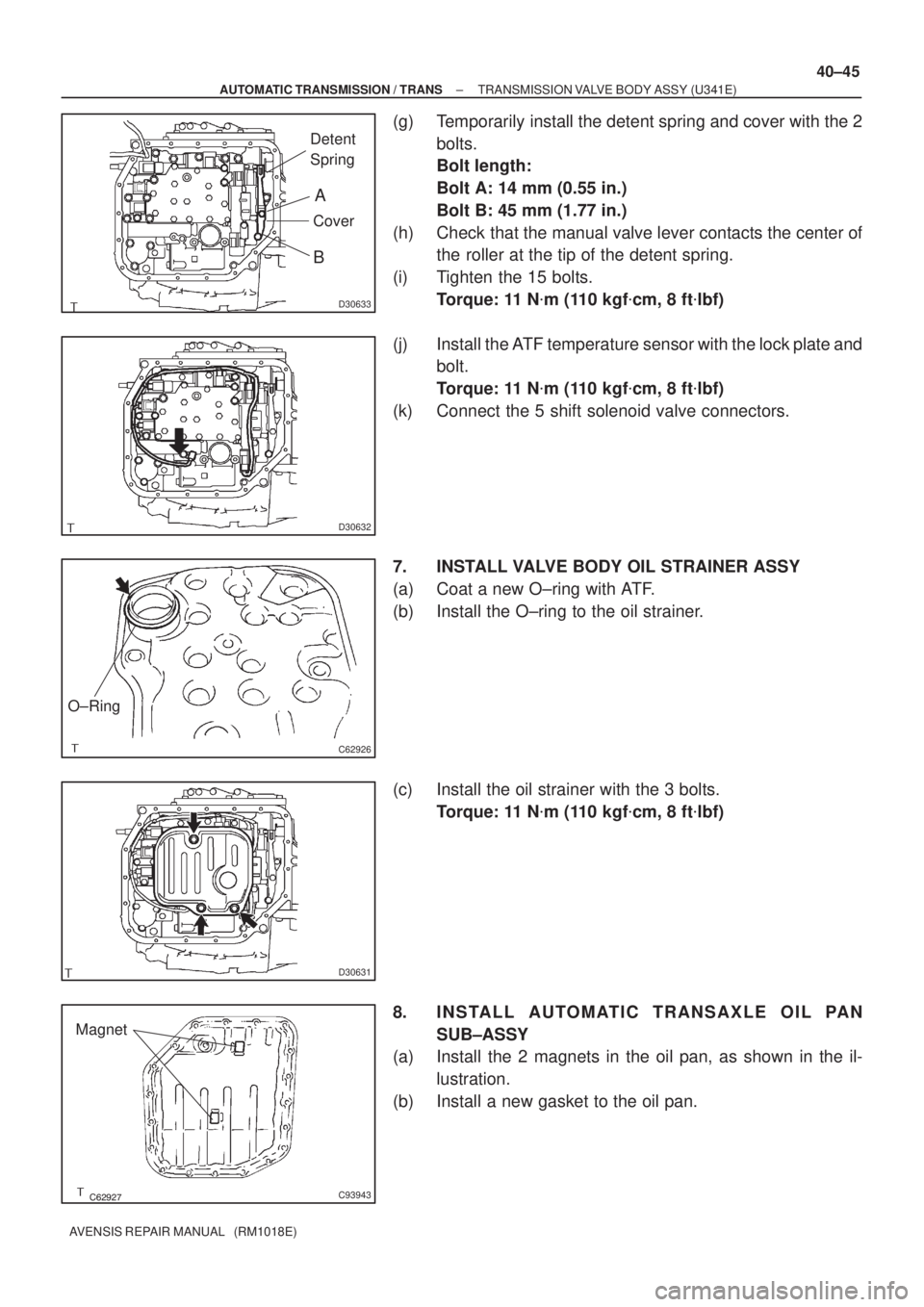
(g) Temporarily install the detent spring and cover with the 2
bolts.
Bolt length:
Bolt A: 14 mm (0.55 in.)
Bolt B: 45 mm (1.77 in.)
(h) Check that the manual valve lever contacts the center of
the roller at the tip of the detent spring.
(i) Tighten the 15 bolts.
Torque: 11 N�m (110 kgf�cm, 8 ft�lbf)
(j) Install the ATF temperature sensor with the lock plate and
bolt.
Torque: 11 N�m (110 kgf�cm, 8 ft�lbf)
(k) Connect the 5 shift solenoid valve connectors.
7. INSTALL VALVE BODY OIL STRAINER ASSY
(a) Coat a new O±ring with ATF.
(b) Install the O±ring to the oil strainer.
(c) Install the oil strainer with the 3 bolts.
Torque: 11 N�m (110 kgf�cm, 8 ft�lbf)
8. INSTALL AUTOMATIC TRANSAXLE OIL PAN
SUB±ASSY
(a) Install the 2 magnets in the oil pan, as shown in the il-
lustration.
(b) Install a new gasket to the oil pan.
Page 2881 of 5135
R11229
NormalAbnormal
R11786Engine Idling Engine Stopped5 mm (0.20 in.)
or less
±
POWER STEERING POWER STEERING SYSTEM
51±5
AVENSIS REPAIR MANUAL (RM1018E)
(c) Start the engine and run it at idle.
(d) Turn the steering wheel from lock to lock several times to
boost fluid temperature.
Fluid temperature: 80 �C (176 �F)
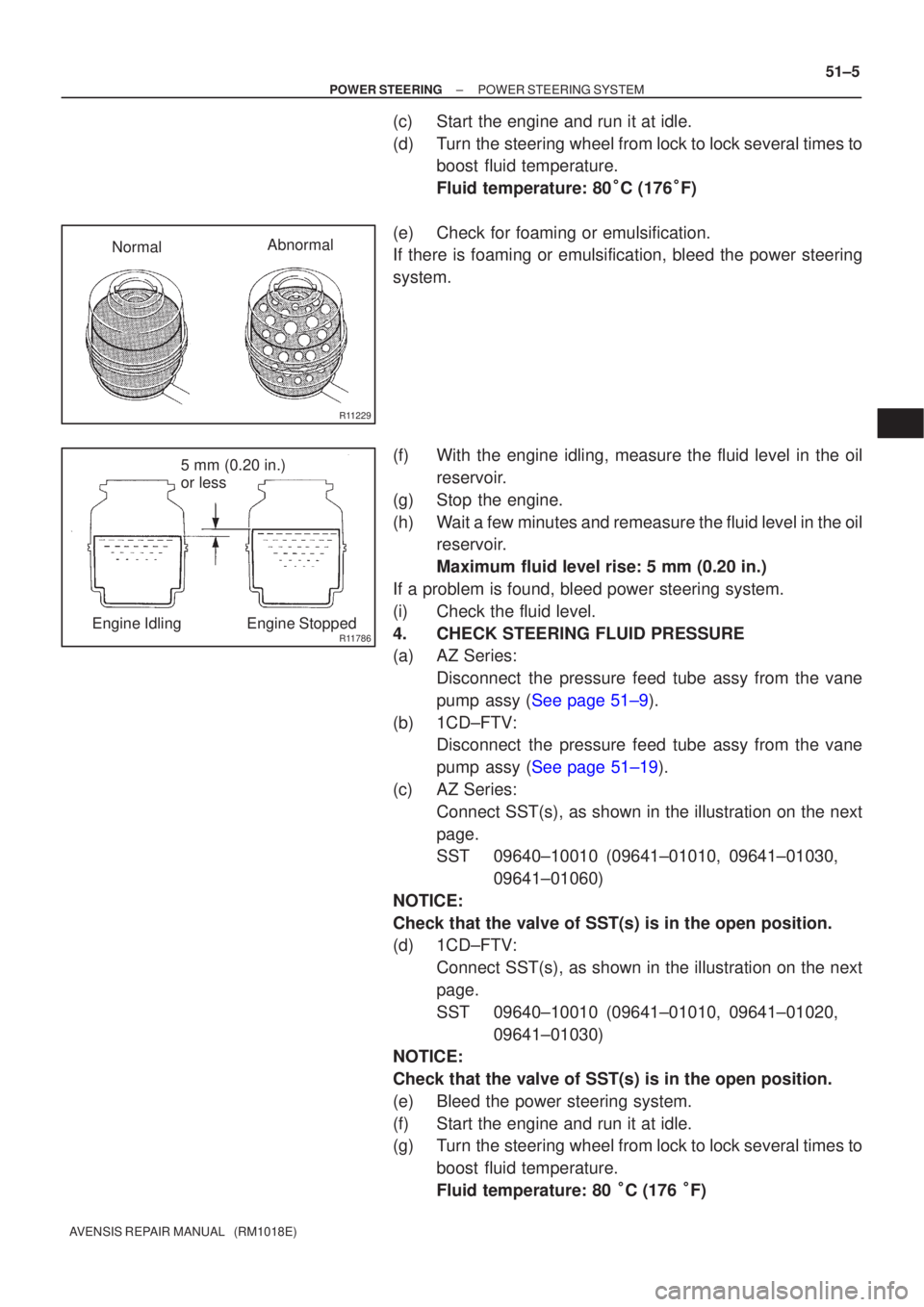
(e) Check for foaming or emulsification.
If there is foaming or emulsification, bleed the power steering
system.
(f) With the engine idling, measure the fluid level in the oil reservoir.
(g) Stop the engine.
(h) Wait a few minutes and remeasure the fluid level in the oil reservoir.
Maximum fluid level rise: 5 mm (0.20 in.)
If a problem is found, bleed power steering system.
(i) Check the fluid level.
4. CHECK STEERING FLUID PRESSURE
(a) AZ Series: Disconnect the pressure feed tube assy from the vane
pump assy (See page 51±9).
(b) 1CD±FTV: Disconnect the pressure feed tube assy from the vane
pump assy (See page 51±19).
(c) AZ Series: Connect SST(s), as shown in the illustration on the next
page.
SST 09640±10010 (09641±01010, 09641±01030, 09641±01060)
NOTICE:
Check that the valve of SST(s) is in the open position.
(d) 1CD±FTV: Connect SST(s), as shown in the illustration on the next
page.
SST 09640±10010 (09641±01010, 09641±01020, 09641±01030)
NOTICE:
Check that the valve of SST(s) is in the open position.
(e) Bleed the power steering system.
(f) Start the engine and run it at idle.
(g) Turn the steering wheel from lock to lock several times to
boost fluid temperature.
Fluid temperature: 80 �C (176 �F)
Page 2882 of 5135
D30364
Attachment
OUT
IN IN OUTAttachment
SST(s) SST(s)
Attachment
Attachment AZ Series:
1CD±FTV:
Z15498
Oil
Reservoir
PS Vane
Pump PS Gear
SST(s) Closed
Z15499
Oil
Reservoir
PS Vane
Pump PS Gear
SST(s) Open 51±6
± POWER STEERINGPOWER STEERING SYSTEM
AVENSIS REPAIR MANUAL (RM1018E)
(h) With the engine idling, close the valve of SST(s) and ob-
serve the reading on SST(s).
Minimum fluid pressure:
AZ Series:
8,300 to 9,000 kPa (85 to 92 kgf/cm
2, 1,204 to 1,305 psi)
1CD±FTV:
8,800 to 9,500 kPa (90 to 97 kgf/cm
2, 1,276 to 1,378 psi)
NOTICE:
�Do not keep the valve closed for more than 10 se-
conds.
�Do not let the fluid temperature become too high.
(i) With the engine idling, open the valve fully.
(j) Measure the fluid pressure at engine speeds of 1,000 rpm
and 3,000 rpm.
Fluid pressure difference:
490 kPa (5 kgf/cm
2, 71 psi) or less
NOTICE:
Do not turn the steering wheel.
Page 2883 of 5135
Z15500
Oil
ReservoirPS Vane
Pump
PS Gear
SST(s)
Open
Lock Position
F08858
±
POWER STEERING POWER STEERING SYSTEM
51±7
AVENSIS REPAIR MANUAL (RM1018E)
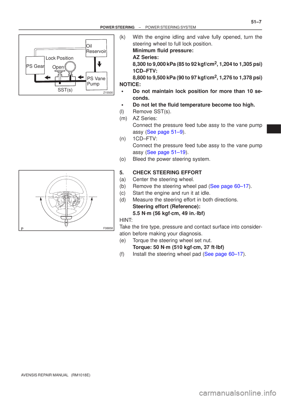
(k) With the engine idling and valve fully opened, turn the
steering wheel to full lock position.
Minimum fluid pressure:
AZ Series:
8,300 to 9,000 kPa (85 to 92 kgf/cm
2, 1,204 to 1,305 psi)
1CD±FTV:
8,800 to 9,500 kPa (90 to 97 kgf/cm
2, 1,276 to 1,378 psi)
NOTICE:
�Do not maintain lock position for more than 10 se-
conds.
�Do not let the fluid temperature become too high.
(l) Remove SST(s).
(m) AZ Series:
Connect the pressure feed tube assy to the vane pump
assy (See page 51±9).
(n) 1CD±FTV:
Connect the pressure feed tube assy to the vane pump
assy (See page 51±19).
(o) Bleed the power steering system.
5. CHECK STEERING EFFORT
(a) Center the steering wheel.
(b)Remove the steering wheel pad (See page 60±17).
(c) Start the engine and run it at idle.
(d) Measure the steering effort in both directions. Steering effort (Reference):
5.5 N´m (56 kgf´cm, 49 in.´lbf)
HINT:
Take the tire type, pressure and contact surface into consider-
ation before making your diagnosis.
(e) Torque the steering wheel set nut. Torque: 50 N´m (510 kgf´cm, 37 ft´lbf)
(f)Install the steering wheel pad (See page 60±17).
Page 3240 of 5135
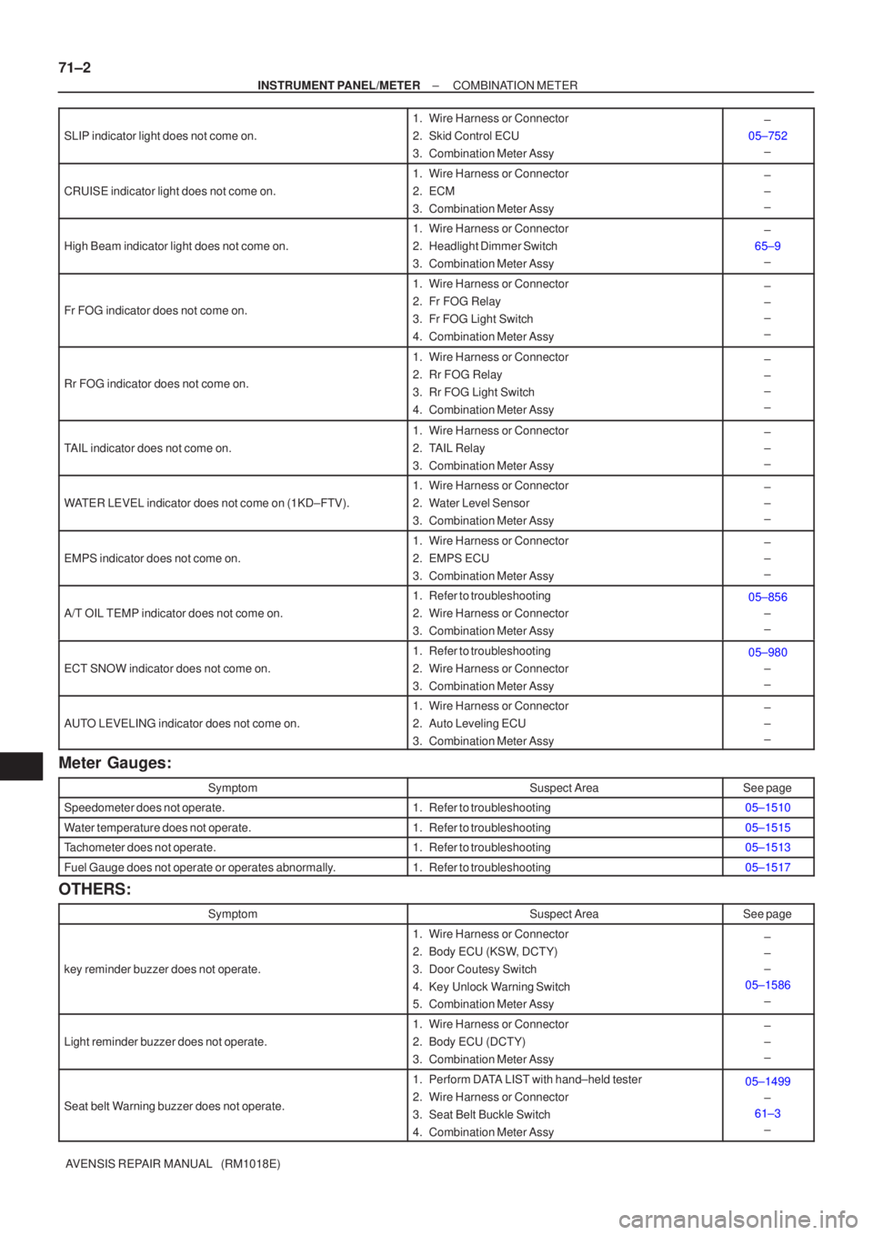
71±2
±
INSTRUMENT PANEL/METER COMBINATION METER
AVENSIS REPAIR MANUAL (RM1018E)
SLIP indicator light does not come on.
1.Wire Harness or Connector
2.Skid Control ECU
3.Combination Meter Assy±
05±752 ±
CRUISE indicator light does not come on.
1.Wire Harness or Connector
2.ECM
3.Combination Meter Assy±
±
±
High Beam indicator light does not come on.
1.Wire Harness or Connector
2.Headlight Dimmer Switch
3.Combination Meter Assy±
65±9 ±
Fr FOG indicator does not come on.
1.Wire Harness or Connector
2.Fr FOG Relay
3.Fr FOG Light Switch
4.Combination Meter Assy±
±
±
±
Rr FOG indicator does not come on.
1.Wire Harness or Connector
2.Rr FOG Relay
3.Rr FOG Light Switch
4.Combination Meter Assy±
±
±
±
TAIL indicator does not come on.
1.Wire Harness or Connector
2.TAIL Relay
3.Combination Meter Assy±
±
±
WATER LEVEL indicator does not come on (1KD±FTV).
1.Wire Harness or Connector
2.Water Level Sensor
3.Combination Meter Assy±
±
±
EMPS indicator does not come on.
1.Wire Harness or Connector
2.EMPS ECU
3.Combination Meter Assy±
±
±
A/T OIL TEMP indicator does not come on.
1.Refer to troubleshooting
2.Wire Harness or Connector
3.Combination Meter Assy05±856
±
±
ECT SNOW indicator does not come on.
1.Refer to troubleshooting
2.Wire Harness or Connector
3.Combination Meter Assy05±980±
±
AUTO LEVELING indicator does not come on.
1.Wire Harness or Connector
2.Auto Leveling ECU
3.Combination Meter Assy±
±
±
Meter Gauges:
SymptomSuspect AreaSee page
Speedometer does not operate.1.Refer to troubleshooting05±1510
Water temperature does not operate.1.Refer to troubleshooting05±1515
Tachometer does not operate.1.Refer to troubleshooting05±1513
Fuel Gauge does not operate or operates abnormally.1.Refer to troubleshooting05±1517
OTHERS:
SymptomSuspect AreaSee page
key reminder buzzer does not operate.
1. Wire Harness or Connector
2. Body ECU (KSW, DCTY)
3. Door Coutesy Switch
4. Key Unlock Warning Switch
5. Combination Meter Assy±
±
±
05±1586 ±
Light reminder buzzer does not operate.
1. Wire Harness or Connector
2. Body ECU (DCTY)
3. Combination Meter Assy±
±
±
Seat belt Warning buzzer does not operate.
1. Perform DATA LIST with hand±held tester
2. Wire Harness or Connector
3. Seat Belt Buckle Switch
4. Combination Meter Assy05±1499±
61±3
±
Page 3434 of 5135
B67164
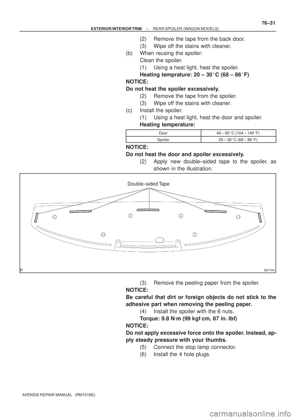
Double±sided Tape
± EXTERIOR/INTERIOR TRIMREAR SPOILER (WAGON MODELS)
76±31
AVENSIS REPAIR MANUAL (RM1018E)
(2) Remove the tape from the back door.
(3) Wipe off the stains with cleaner.
(b) When reusing the spoiler:
Clean the spoiler.
(1) Using a heat light, heat the spoiler.
Heating temprature: 20 ± 30�C (68 ± 86�F)
NOTICE:
Do not heat the spoiler excessively.
(2) Remove the tape from the spoiler.
(3) Wipe off the stains with cleaner.
(c) Install the spoiler.
(1) Using a heat light, heat the door and spoiler.
Heating temperature:
Door40 ± 60�C (104 ± 140�F)
Spoiler20 ± 30�C (68 ± 86�F)
NOTICE:
Do not heat the door and spoiler excessively.
(2) Apply new double±sided tape to the spoiler, as
shown in the illustration.
(3) Remove the peeling paper from the spoiler.
NOTICE:
Be careful that dirt or foreign objects do not stick to the
adhesive part when removing the peeling paper.
(4) Install the spoiler with the 6 nuts.
Torque: 9.8 N�m (99 kgf�cm, 87 in.�lbf)
NOTICE:
Do not apply excessive force onto the spoiler. Instead, ap-
ply steady pressure with your thumbs.
(5) Connect the stop lamp connector.
(6) Install the 4 hole plugs.