Page 4615 of 5135

A93407SST
−
ENGINE MECHANICAL CYLINDER HEAD GASKET (1CD −FTV)(From
September, 2003)14 −167
AVENSIS Supplement (RM1045E)
43. REMOVE TURBO INSULATOR NO.2 (See page 13 −12)
44. REMOVE TURBO INSULATOR NO.1 (See page 13 −12)
45. REMOVE EXHAUST MANIFOLD HEAT INSULATOR NO.2 (See page 13 −12)
46. REMOVE EGR PIPE INSULATOR (See page 13 −12)
47. REMOVE GENERATOR ASSY (See Pub. No. RM1018E on page 19 −29)
48. REMOVE EXHAUST GAS TEMPERATURE SENSOR (See page 14 −108)
SST 09023 −38400
49. REMOVE VACUUM TRANSMITTING PIPE SUB −ASSY NO.1 (See page 14 −108)
SST 09023 −38200
50. REMOVE VACUUM TRANSMITTING PIPE SUB −ASSY NO.2 (See page 14 −108)
SST 09023 −38200
51. REMOVE MANIFOLD STAY NO.2 (See page 13 −12)
52. REMOVE MANIFOLD STAY (See page 13 −12)
53. REMOVE MANIFOLD CONVERTER SUB −ASSY (See page 13 −12)
54. REMOVE TURBOCHARGER STAY (See page 13 −12)
55. REMOVE TURBO WATER HOSE NO.1 (See page 13 −12)
56. REMOVE TURBO WATER HOSE NO.2 (See page 13 −12)
57. SEPARATE TURBO OIL INLET PIPE SUB −ASSY (See page 13 −12)
58. REMOVE TURBOCHARGER SUB −ASSY (See page 13 −12)
59. REMOVE CAMSHAFT POSITION SENSOR (See page 14 −108)
60. REMOVE CAMSHAFT TIMING PULLEY (See page 14 −151)
SST 09960 −10010 (09962 −01000, 09963 −01000)
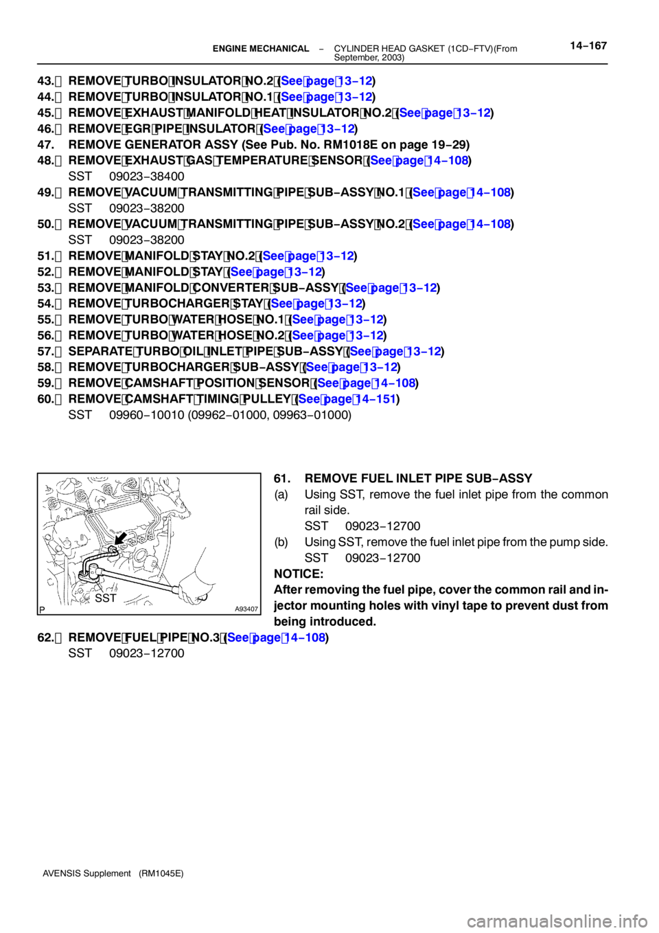
61. REMOVE FUEL INLET PIPE SUB −ASSY
(a) Using SST, remove the fuel inlet pipe from the common rail side.
SST 09023 −12700
(b) Using SST, remove the fuel inlet pipe from the pump side.
SST 09023 −12700
NOTICE:
After removing the fuel pipe, cover the common rail and in-
jector mounting holes with vinyl tape to prevent dust from
being introduced.
62. REMOVE FUEL PIPE NO.3 (See page 14 −108)
SST 09023 −12700
Page 4623 of 5135

A87960
Fulcrum Length
30 cm (11.81 in.)
SST
−
ENGINE MECHANICAL CYLINDER HEAD GASKET (1CD −FTV)(From
September, 2003)14 −175
AVENSIS Supplement (RM1045E)
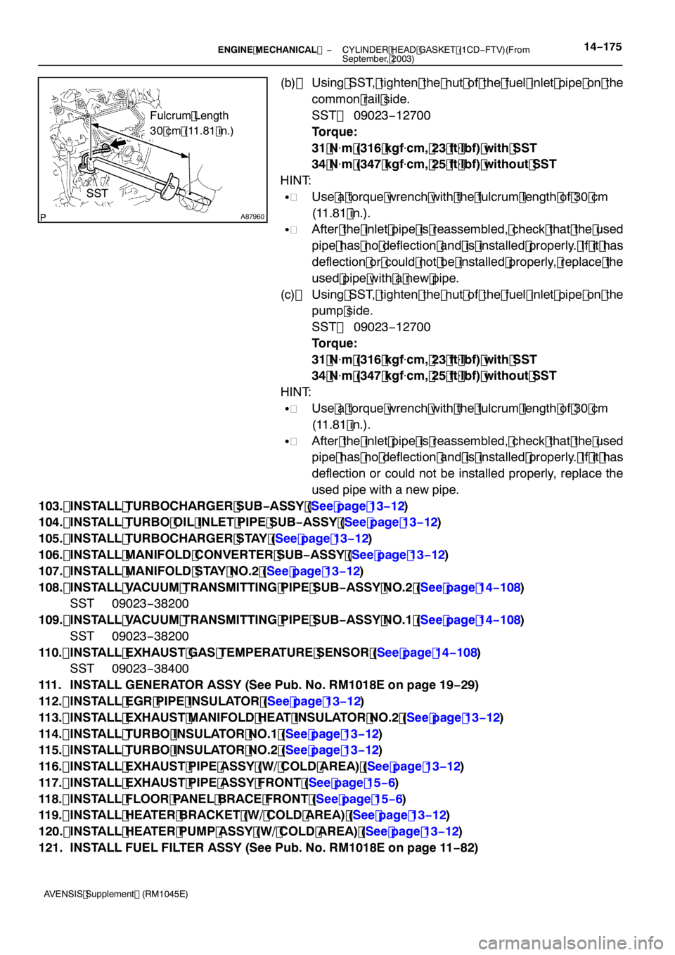
(b) Using SST, tighten the nut of the fuel inlet pipe on the
common rail side.
SST 09023 −12700
Torque:
31 N �m (316 kgf �cm, 23 ft �lbf) with SST
34 N �m (347 kgf �cm, 25 ft �lbf) without SST
HINT:
S Use a torque wrench with the fulcrum length of 30 cm
(11.81 in.).
S After the inlet pipe is reassembled, check that the used
pipe has no deflection and is installed properly. If it has
deflection or could not be installed properly, replace the
used pipe with a new pipe.
(c) Using SST, tighten the nut of the fuel inlet pipe on the pump side.
SST 09023 −12700
Torque:
31 N �m (316 kgf �cm, 23 ft �lbf) with SST
34 N �m (347 kgf �cm, 25 ft �lbf) without SST
HINT:
S Use a torque wrench with the fulcrum length of 30 cm
(11.81 in.).
S After the inlet pipe is reassembled, check that the used
pipe has no deflection and is installed properly. If it has
deflection or could not be installed properly, replace the
used pipe with a new pipe.
103. INSTALL TURBOCHARGER SUB −ASSY (See page 13 −12)
104. INSTALL TURBO OIL INLET PIPE SUB −ASSY (See page 13 −12)
105. INSTALL TURBOCHARGER STAY (See page 13 −12)
106. INSTALL MANIFOLD CONVERTER SUB −ASSY (See page 13 −12)
107. INSTALL MANIFOLD STAY NO.2 (See page 13 −12)
108. INSTALL VACUUM TRANSMITTING PIPE SUB −ASSY NO.2 (See page 14 −108)
SST 09023 −38200
109. INSTALL VACUUM TRANSMITTING PIPE SUB −ASSY NO.1 (See page 14 −108)
SST 09023 −38200
110. INSTALL EXHAUST GAS TEMPERATURE SENSOR (See page 14 −108)
SST 09023 −38400
111. INSTALL GENERATOR ASSY (See Pub. No. RM1018E on page 19 −29)
112. INSTALL EGR PIPE INSULATOR (See page 13 −12)
113. INSTALL EXHAUST MANIFOLD HEAT INSULATOR NO.2 (See page 13 −12)
114. INSTALL TURBO INSULATOR NO.1 (See page 13 −12)
115. INSTALL TURBO INSULATOR NO.2 (See page 13 −12)
116. INSTALL EXHAUST PIPE ASSY (W/ COLD AREA) (See page 13 −12)
117. INSTALL EXHAUST PIPE ASSY FRONT (See page 15 −6)
118. INSTALL FLOOR PANEL BRACE FRONT (See page 15 −6)
119. INSTALL HEATER BRACKET (W/ COLD AREA) (See page 13 −12)
120. INSTALL HEATER PUMP ASSY (W/ COLD AREA) (See page 13 −12)
121. INSTALL FUEL FILTER ASSY (See Pub. No. RM1018E on page 11 −82)
Page 4656 of 5135
A84290
A84291
A15985
A84397
(a)
(a)
(b)
−
ENGINE MECHANICAL PARTIAL ENGINE ASSY (1CD −FTV)(From September,
2003)14 −11 5
AVENSIS Supplement (RM1045E)
70. REMOVE V −RIBBED BELT TENSIONER ASSY
(a) Remove the 3 bolts and V −ribbed belt tensioner.
71. REMOVE V −RIBBED BELT TENSIONER BRACKET
(a) Remove the bolt and V −ribbed belt tensioner bracket.
72. REMOVE OIL FILTER BRACKET SUB −ASSY
(a) Remove the bolt and 2 nuts, then remove the oil filter
bracket and gasket.
73. REMOVE TURBO INSULATOR NO.2 (See page 13 −12)
74. REMOVE TURBO INSULATOR NO.1 (See page 13 −12)
75. REMOVE EXHAUST MANIFOLD HEAT INSULATOR NO.2 (See page 13 −12)
76. REMOVE EGR PIPE INSULATOR (See page 13 −12)
77. REMOVE EXHAUST GAS TEMPERATURE SENSOR
(a) Remove the 2 nuts, then detach the wire harness from the clamp.
(b) Disconnect the connector.
Page 4663 of 5135

A84380
A84378
14−122−
ENGINE MECHANICAL PARTIAL ENGINE ASSY (1CD −FTV)(From September,
2003)
AVENSIS Supplement (RM1045E)
116. REMOVE FUEL FILTER TO INJECTION PUMP FUEL PIPE
(a) Remove the 3 bolts and fuel pipe.
117. REMOVE CRANKSHAFT POSITION SENSOR
(a) Remove the bolt and crankshaft position sensor.
118. REMOVE CAMSHAFT POSITION SENSOR
(a) Remove the bolt and camshaft position sensor. 119. REM O VE ENG I NE CO O L ANT TEM PERAT URESENSOR
120. REPLACE PARTIAL ENGINE ASSY
121. INSTALL ENGINE COOLANT TEMPERATURE SENSOR Torque: 20 N �m (200 kgf �cm, 14 ft �lbf)
122. INSTALL CAMSHAFT POSITION SENSOR Torque: 8.8 N �m (90 kgf �cm, 78 in. �lbf)
123. INSTALL CRANKSHAFT POSITION SENSOR Torque: 8.8 N �m (90 kgf �cm, 78 in. �lbf)
124. INSTALL FUEL FILTER TO INJECTION PUMP FUEL PIPE
Torque:
8.8 N�m (90 kgf �cm, 78 in. �lbf) for M6
21 N �m (209 kgf �cm, 15 ft �lbf) for M8
125. INSTALL OIL COOLER PIPE
(a) Using a socket wrench for 27 mm, install 2 new gaskets and the oil cooler pipe with the union bolt. Torque: 56 N �m (575 kgf �cm, 42 ft �lbf)
126. INSTALL THERMOSTAT (See Pub. No. RM1018E on page 16 −50)
127. INSTALL WATER INLET (See Pub. No. RM1018E on page 16 −50)
128. INSTALL COMPRESSOR MOUNTING BRACKET NO.1 (W/ AIR CONDITIONING)
Torque: 42 N �m (428 kgf �cm, 31 ft �lbf)
129. INSTALL INJECTION OR SUPPLY PUMP ASSY (See page 11 −58)
130. INSTALL INJECTION PUMP STAY NO.1 (See page 11 −58)
131. INSTALL OIL LEVEL GAGE GUIDE (See page 17 −11 )
132. INSTALL TIMING BELT NO.3 COVER Torque: 7.4 N �m (75 kgf �cm, 65 in. �lbf)
Page 4669 of 5135

A85921
5mm
(0.20 in.)
A85914
SST
A8592215 mm (0.59 in.)
A87961
SST
14−128−
ENGINE MECHANICAL PARTIAL ENGINE ASSY (1CD −FTV)(From September,
2003)
AVENSIS Supplement (RM1045E)
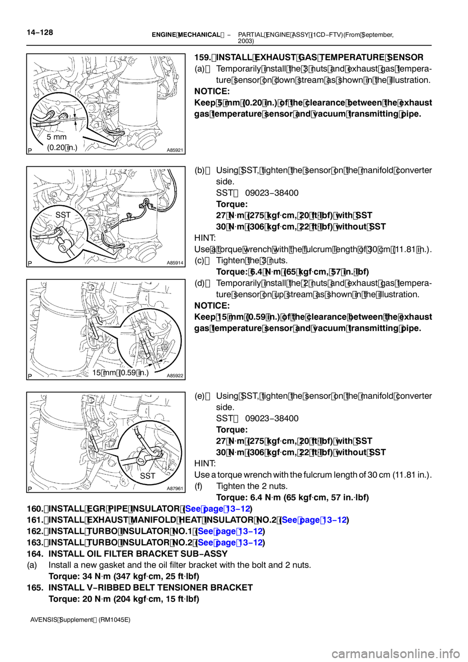
159. INSTALL EXHAUST GAS TEMPERATURE SENSOR
(a) Temporarily install the 3 nuts and exhaust gas tempera- ture sensor on down stream as shown in the illustration.
NOTICE:
Keep 5 mm (0.20 in.) of the clearance between the exhaust
gas temperature sensor and vacuum transmitting pipe.
(b) Using SST, tighten the sensor on the manifold converter
side.
SST 09023 −38400
Torque:
27 N �m (275 kgf �cm, 20 ft �lbf) with SST
30 N �m (306 kgf �cm, 22 ft �lbf) without SST
HINT:
Use a torque wrench with the fulcrum length of 30 cm (11.81 in.).
(c) Tighten the 3 nuts.
Torque: 6.4 N �m (65 kgf �cm, 57 in. �lbf)
(d) Temporarily install the 2 nuts and exhaust gas tempera- ture sensor on up stream as shown in the illustration.
NOTICE:
Keep 15 mm (0.59 in.) of the clearance between the exhaust
gas temperature sensor and vacuum transmitting pipe.
(e) Using SST, tighten the sensor on the manifold converter side.
SST 09023 −38400
Torque:
27 N �m (275 kgf �cm, 20 ft �lbf) with SST
30 N �m (306 kgf �cm, 22 ft �lbf) without SST
HINT:
Use a torque wrench with the fulcrum length of 30 cm (11.81 in.).
(f) Tighten the 2 nuts.
Torque: 6.4 N �m (65 kgf �cm, 57 in. �lbf)
160. INSTALL EGR PIPE INSULATOR (See page 13 −12)
161. INSTALL EXHAUST MANIFOLD HEAT INSULATOR NO.2 (See page 13 −12)
162. INSTALL TURBO INSULATOR NO.1 (See page 13 −12)
163. INSTALL TURBO INSULATOR NO.2 (See page 13 −12)
164. INSTALL OIL FILTER BRACKET SUB −ASSY
(a) Install a new gasket and the oil filter bracket with the bolt and 2 nuts.
Torque: 34 N �m (347 kgf �cm, 25 ft �lbf)
165. INSTALL V −RIBBED BELT TENSIONER BRACKET
Torque: 20 N �m (204 kgf �cm, 15 ft �lbf)
Page 4717 of 5135
A89211
N·m (kgf·cm, ft·lbf)
: Specified torque
zNon−reusable part zO−ringzGasket zBack−Up Ring No. 1
20 (208, 15)
21 (210, 15)21 (210, 15)
20 (208, 15)
Engine Coolant
Temperature Sensor
Engine Oil Pressure
Switch Assy
Surge Tank Stay No. 1
Insulator No. 2
zE−ring
zBack−Up Ring No. 3
zFuel Injector Seal
13 (127, 9.0)
Fuel Delivery
Pipe Sub−assy
Nozzle Holder Clamp
Knock Sensor
15 (153, 11)
Fuel Injector
zBack−Up Ring No. 2zO−ring19 (194, 14)
14−22
− ENGINE MECHANICALPARTIAL ENGINE ASSY (2AZ−FSE)
AVENSIS Supplement (RM1045E)
Page 4772 of 5135

40188−01
C91925
D30865
AT0103
C91927
− AUTOMATIC TRANSMISSION / TRANSTRANSMISSION VALVE BODY ASSY (U151E)
40−19
AVENSIS Supplement (RM1045E)
TRANSMISSION VALVE BODY ASSY (U151E)
REPLACEMENT
1. REMOVE ENGINE UNDER COVER LH
2. DRAIN AUTOMATIC TRANSAXLE FLUID
(a) Remove the drain plug and gasket, and drain ATF.
(b) Install a new gasket and the drain plug.
Torque: 47 N�m (479 kgf�cm, 35 ft�lbf)
3. REMOVE AUTOMATIC TRANSAXLE OIL PAN
SUB−ASSY
(a) Remove the 18 bolts, oil pan and gasket.
NOTICE:
Some fluid will remain in the oil pan. Remove all of the oil
pan bolts, and carefully remove the oil pan assembly.
(b) Remove the 2 magnets from the oil pan.
(c) Examine the particles in the oil pan.
(1) Collect any steel chips with the removed magnets.
Look at the chips and particles in the pan and on the
magnets carefully to see the type of wear which
might be found in the transaxle.
Steel (magnetic): bearing, gear and plate wear
Brass (non−magnetic): bearing wear
4. DISCONNECT TRANSMISSION WIRE
(a) Disconnect the 7 shift solenoid valve connectors.
(b) Remove the bolt and lock plate, and disconnect the ATF
temperature sensor.
Page 4775 of 5135

C91933
A
B
CB
B
B
A
CCC
L
L
C
B
C91932
C91931
C91927
40−22
− AUTOMATIC TRANSMISSION / TRANSTRANSMISSION VALVE BODY ASSY (U151E)
AVENSIS Supplement (RM1045E)
(c) Align the groove of the manual valve with the pin of the
lever.
(d) Install the 17 bolts.
Torque:11N�m(110 kgf�cm, 8 ft�lbf)
NOTICE:
SPush the valve body against the accumulator piston
spring and the check ball body to install it.
SFirst, temporarily tighten those bolts marked byLin
the illustration because they are positioning bolts.
Bolt length:
Bolt A: 25 mm (0.984 in.)
Bolt B: 57 mm (2.244 in.)
Bolt C: 41mm (1.614 in.)
8. INSTALL VALVE BODY OIL STRAINER ASSY
(a) Coat a new O−ring with ATF.
(b) Install the O−ring to the oil strainer.
(c) Install the oil strainer with the 3 bolts.
Torque:11N�m(110 kgf�cm, 8 ft�lbf)
9. INSTALL TRANSMISSION WIRE
(a) Coat an O−ring with ATF.
(b) Install the ATF temperature sensor with the lock plate and
bolt.
Torque: 6.6 N�m (67 kgf�cm, 58 in.�lbf)
(c) Connect the 7 shift solenoid valve connectors.